Danfoss 102 Installation And Wiring Instructions
Gp programmers & timeswitches for time control of domestic central heating systems
Hide thumbs
Also See for 102:
- Operating instructions manual (94 pages) ,
- Reference manual (60 pages) ,
- Installation & user's instructions (12 pages)
Advertisement
Quick Links
GP
Programmers & Timeswitches
102, 103 and 106 Models, for time control of Domestic Central
Heating Systems.
INSTALLATION AND WIRING INSTRUCTIONS
SPECIFICATIONS
Power Supply
: 220/240Vac, 50/Hz
Switch Action
: 1 x SPST, Type 1B
Switch Rating
: 220/240Vac, 50/60Hz, 6(2)A.
Timing Accuracy
: ± 1 min./month
Enclosure Rating
: IP20
Pollution Situation
: Degree 2
Max. Ambient Temp.
: 55°C
Designed to meet BS EN60730-2-7
Dimensions
: 112mm wide, 135mm high, 69mm deep
Rated Impulse voltage
: 2.5kV
Ball Pressure Test
: 75°C
The unit must be installed by a competent electrician and the installation
should conform to I.E.E. Regulations. This unit should be wired via full
disconnect in accordance with BS EN60730-1, e.g. via a plug and unswitched
socket or double pole switch outlet with neon.
INSTALLATION INSTRUCTIONS
1. Loosen the fi xing screw in the base of the unit to release the grey
plastic Wiring Cover. Ensure the protective tape over the thumbwheel
remains in place.
2. Holding the unit clockface downwards, press fi rmly in the centre of
the wallplate and slide it from the module as shown.
3. Fix the Wallplate/Terminal Block to the wall with countersunk No.8
woodscrews or to a steel box to BS 4662. 1970 or a surface mounting
steel or moulded box having centres of 2
4. Referring to the Wiring Diagrams overleaf, connect the unit as shown.
Ensure that terminals 3 and 6 are linked where required (Mains
Voltage applications) with insulated cable capable of carrying full load
current.
5. Ensure all dust and debris have been cleared away from the area, then
plug the module fi rmly into the wallplate ensuring that the hook at
the top of the wallplate engages with the slot at the back of the body.
Press the module down until it locates solidly.
6. Cut a cable aperture in the Wiring Cover if necessary; replace the Wiring
Cover, and tighten the fi xing screw.
7. Switch on Mains and test for correct operation as follows:
i)
Remove protective tape from the pre-selector wheel.
ii) Remove the dial cover and rotate the clock dial two complete
revolutions to clear the mechanism.
ii) Check that all positions of the Selector Switch and Tappets operate
correctly. (See instructions in User Booklet.)
8. Replace the dial cover. Finally leave the USER INSTRUCTIONS with the
Householder.
9. If the unit is to be left turned off and is in a dusty atmosphere, protect
the pre-selector wheel by re-affi xing the protective tape.
IMPORTANT: Remove tape prior to putting unit into service.
3
/
" (60.3mm).
8
This product complies with the following EC Directives:
Electro-Magnetic Compatibility Directive.
(EMC) (2004/108/EC)
Low Voltage Directive.
(LVD) (2006/95/EC)
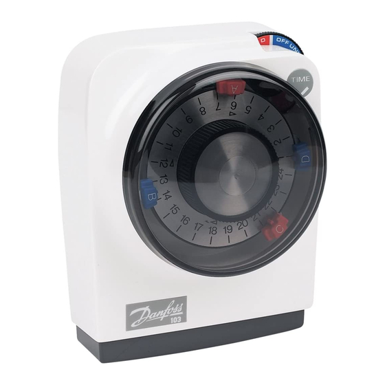
Pre-Selector Wheel
Selector Switch
Plug-in Replacement
Module
Wallplate/Terminal Block
Wallplate/
Terminal Block
Plug-in Module
1
Advertisement

Related Manuals for Danfoss 102


Summary of Contents for Danfoss 102
- Page 1 Programmers & Timeswitches 102, 103 and 106 Models, for time control of Domestic Central Heating Systems. INSTALLATION AND WIRING INSTRUCTIONS SPECIFICATIONS This product complies with the following EC Directives: Power Supply : 220/240Vac, 50/Hz Electro-Magnetic Compatibility Directive. (EMC) (2004/108/EC) Switch Action : 1 x SPST, Type 1B Low Voltage Directive.
- Page 2 Danfoss Randall can accept no responsibility for possible errors in catalogues, brochures and other printed material. Danfoss Randall reserves the right to alter its products without notice. This also applies to products already on order provided that such alterations can be made without subsequent changes being necessary in specifi...