Table of Contents
Advertisement
Quick Links
Advertisement
Table of Contents

Summary of Contents for Icom IC-G88
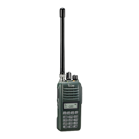
- Page 1 OPERATING GUIDE VHF TRANSCEIVER Iç-G88...
-
Page 2: Table Of Contents
VFO Set mode ..............6 User Set mode ..............7 Icom, Icom Inc. and Icom logo are registered trademarks of Icom Incorpo- rated (Japan) in Japan, the United States, the United Kingdom, Germany, France, Spain, Russia, Australia, New Zealand, and/or other countries. -
Page 3: Accessories
Section ACCESSORIES Accessory attachments D Antenna Connect the supplied antenna to the antenna connector. CAUTION: • NEVER carry the transceiver by holding only the antenna. • DO NOT connect any antenna other than that is sup- plied with the transceiver. •... -
Page 4: D Jack Cover
ACCESSORIES Accessory attachments (Continued) D Jack cover To attach the jack cover: q Place the jack cover over the speaker-microphone jack. w Insert and tighten the screws. CAUTION: The transceiver meets IP67 requirements for dust-tight and waterproof protection, only when the jack cover or the optional HM-168LWP speaker is attached. -
Page 5: Programmable Key Functions
Section PROGRAMMABLE KEY FUNCTIONS Programmable key functions If you use the CS-G88 High/Low programming software (purchase separately), you can assign the functions ➥ Push to select the output power. described below to [P0], [P1], [P2], [P3], [TOP], [UP], and [DOWN]. Wide/Narrow ➥... -
Page 6: Programmable Key Functions
PROGRAMMABLE KEY FUNCTIONS Programmable key functions (Continued) VFO / User Set Mode ➥ Push to enter the VFO Set mode. • The VFO Set mode is used to change settings for the operation in the VFO mode. ➥ Hold down for 1 second to enter the User Set mode. •... -
Page 7: Mdc 1200 System Operation
An additional feature of the MDC 1200 system included eration. in Icom transceivers is called aliasing. Each transceiver on the system has a unique ID number. Aliasing is a substitute for this ID number and you can give an al- phanumeric name for each station ID. -
Page 8: Set Modes
Section SET MODES The are 2 Set modes: User Set mode and VFO Set mode. User Set mode The User Set mode enables you to change various settings. You can “customize” the transceiver operation to suit your preferences and operating style. Entering the User Set mode: Exiting the User Set mode: ➥... -
Page 9: User Set Mode
SET MODES VFO Set mode The VFO Set mode enables you to change various settings for the operation in the VFO mode. You can change the operating condition in this mode. Entering the VFO Set mode: Exiting the VFO Set mode: ➥... - Page 10 SCAN OPERATION VFO Set mode (Continued) DTCS Polarity Sets the DTCS polarity for transmit and receive. • Select “RR” (TX/RX Reverse), “RN” (TX Reverse, RX Normal), “NR” (TX Normal, RX Reverse) or “NN” (TX/RX Normal). TX Inhibit Selects whether or not to inhibit transmitting on the channel.
- Page 11 A7450-3EX 1-1-32 Kamiminami, Hirano-ku, Osaka 547-0003, Japan © 2018 Icom Inc.


