Advertisement
Quick Links
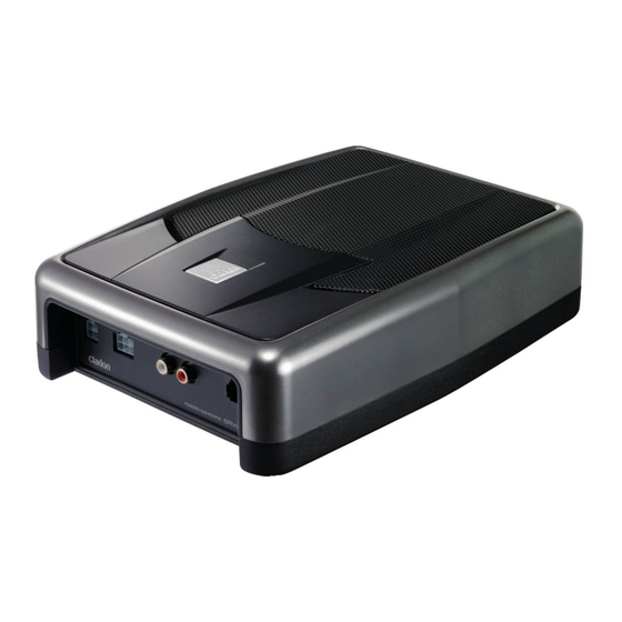
SRV250
English
■ Thank you for purchasing this Clarion
product.
• Please read through this instruction manual
before operating the equipment.
• Check the contents of the enclosed warranty
card and store it in a safe place with this
manual.
PACKAGE CONTENTS
1
2
1 Power supply cord (16.4 ft / 5 m) ............... 1
SPECIFICATIONS
2 Speaker input cord (16.4 ft / 5 m) .............. 1
3 Remote control unit extension cord
● Maximum Output : 150W (75W + 75W)
(13.1 ft / 4 m) .............................................. 1
● Rated Output : 74W (37W + 37W)
4 Remote control unit (cord 6.6 ft / 2 m) ....... 1
● Frequency Response : 30 - 200Hz
5 Mounting bracket ....................................... 2
● Low-Pass Filter Cut-off Frequency : 50 ~
6 Screw (M5 mm x 6 mm) ............................. 4
120Hz (75/100Hz click position)
7 Tapping screw (Φ5 mm x 16 mm) .............. 4
● RCA Input Sensitivity : 60mV - 4V
8 Speed nut ................................................... 4
● Speaker Input Sensitivity : 2 - 5V
9 Hook-and-loop fastener - small
● Power Source Voltage : DC14.4V
(male/ female) ............................................ 1
● Ground : Negative
0 Hook-and-loop fastener - large
● Consumption current : 7.0A
(male/female) ............................................. 2
● Auto-Fuse Capacity : 10A
● External Dimensions :
• Main Unit : 10-13/16" (275mm) Width x
2-3/4" (70mm) Height x 7-11/16" (195mm)
Depth
• Remote Control Unit : 1-1/4" (32mm) Width
x 1" (24.5mm) Height x 4-3/8" (111mm)
Depth
● Weight :
• Main Unit : 2,500g (5.5lbs)
• Remote Control Unit : 90g (0.2lbs)
6-3/4"(16.5cm) Powered
SAFETY PRECAUTIONS
WARNING
● This unit is for use in DC12V negative
earth cars.
● Before making connections, disconnect
the negative battery terminal. Failure
to do so may cause a short circuit,
resulting in electric shock or fire.
● When mounting or making connections,
avoid places that would obstruct
operation of the air bags. Inability of the
air bag system to operate normally may
result in injury.
● When mounting and connecting ground
wires, do not use bolts or nuts from the
steering system, brake system, tanks or
any other of the vehicle's safety-related
parts. Doing so may result in loss of
control, fire or traffic accident.
● After mounting and making connections,
check that the brake lights, horn, hazard
lamps, blinkers and other electrical
equipment in the vehicle operate
normally. Malfunctioning equipment
may lead to fire, electric shock or traffic
accident.
● Do not attempt to disassemble or modify
the unit. Doing so may lead to accident,
fire or electric shock.
● When changing a fuse, be sure to use
a fuse with the specified capacity. Use
of any other fuse may lead to fire or
malfunction.
● Discontinue use in the event of
malfunction* or abnormality*.
* If no sound is output or there is crackling
or distortion.
* If a foreign object gets inside the unit,
the unit gets splashed with water, smoke
appears or there is an abnormal sound or
smell.
CAUTION
● Avoid mounting the unit where it will
be exposed to rain, humidity or dust.
If water, humidity or dust gets inside
the unit, it may cause smoke, fire or
breakdown.
● Be sure to use the accessories and
specified parts. Failure to do so may
lead to accident or breakdown.
● Follow the instruction manual when
mounting and making connections.
Incorrect wiring may result in fire.
● When making holes in the vehicle
chassis to mount the unit, avoid
interference or contact with the pipes,
tanks or electrical wiring. Damaged
pipes or other parts may lead to fire or
accident.
● To clean the unit, wipe with a soft dry
cloth. If the unit is very dirty, wipe with
a soft cloth containing mild detergent
diluted with water and finish with a dry
cloth. Do not use benzine, thinner, car
cleaner or other organic solvents as this
may lead to deterioration or peeling of
the paint.
3
4
Sub-Woofer
Instruction Manual
5
6
7
8
9
0
SE-308A
Advertisement

Summary of Contents for Clarion SRV250
- Page 1 SRV250 6-3/4”(16.5cm) Powered Sub-Woofer Instruction Manual SAFETY PRECAUTIONS English ■ Thank you for purchasing this Clarion WARNING product. ● This unit is for use in DC12V negative • Please read through this instruction manual earth cars. before operating the equipment.
- Page 2 NAMES AND FUNCTIONS OF PARTS ■ ■ REAR PANEL REMOTE CONTROL UNIT REMOTE CONTROL FREQ GAIN Remote control input terminal * If the woofer level can be controlled from the center unit, the unit can Cut-off frequency adjustment knob Gain control knob be used without connecting the remote control unit.


