
Related Manuals for Baldor BC140

Summary of Contents for Baldor BC140
- Page 1 SCR DC MOTOR CONTROL BC140 / BC140-FBR DC CONTROL Installation and Operation Manual 11/11 MN703...
-
Page 2: Table Of Contents
Table of Contents SAFETY NOTICES ............... . 1. - Page 3 Baldor District Offices ........
- Page 4 WARNING! This product should be installed and serviced by a qualified technician, electrician or electrical maintenance person familiar with its operation and the hazards involved. Proper installation, which includes wiring, mounting in proper enclosure, fusing or other overcurrent protection and grounding, can reduce the chance of electric shocks, fires or explosion in the product or products used with this product, such as electric motors, switches, coils, solenoids or relays.
-
Page 5: Safety Notices
SAFETY NOTICES WARNING - STATEMENT INDICATES A POTENTIALLY HAZARDOUS SITUATION WHICH, IF NOT AVOIDED, COULD RESULT IN INJURY OR DEATH. CAUTION - Statement indicates a potentially hazardous situation which, if not avoided, could result in damage to property. Note - Additional information that is not critical to the installation or operation. WARNING! READ ALL SAFETY NOTICES BEFORE ATTEMPTING TO USE THIS CONTROL. - Page 6 WARNING! ELECTRICAL SHOCK CAN CAUSE SERIOUS OR FATAL INJURY. BE SURE THAT ALL POWER IS DISCONNECTED FROM THE CONTROL BEFORE THE COVER IS OPENED. OPENING OF THE COVER IS REQUIRED TO MAKE INSTALLATION CONNECTIONS. ELECTRICAL SHOCK CAN CAUSE SERIOUS OR FATAL INJURY IF THE COVER IS REMOVED AND POWER IS STILL APPLIED.
- Page 7 WARNING! AUTOMATIC START: THE CONTROL WILL AUTOMATICALLY START WHEN THE POWER IS APPLIED AND THE ON/OFF AC LINE SWITCH IS SET TO THE “ON” POSITION. WARNING! HIGH VOLTAGE IS PRESENT IN THIS CONTROL. DISCONNECT MAIN POWER BEFORE MAKING CONNECTIONS TO THE CONTROL. TO PREVENT ACCIDENTAL CONTACT WITH HIGH VOLTAGE, IT IS REQUIRED THAT THE COVER BE PROPERLY INSTALLED AFTER ALL SETUP, CONNECTIONS, AND ADJUSTMENTS ARE COMPLETE.
- Page 8 CAUTION! Disconnect motor leads (A- and A+) from control before performing a “Leakage Resistance” test on the motor. Failure to disconnect motor from the control may result in extensive damage to the control. The control is tested at the factory for high voltage/leakage resistance as part of Underwriters Laboratories requirements.
- Page 9 CAUTION! If the current limit is adjusted above 160% of the motor nameplate rating, this can cause overheating of the motor. CAUTION! Do not leave the motor in a locked rotor condition for more than a few seconds since damage may occur.
-
Page 10: Introduction
Plug-in Horsepower Resistor ® The standard model, BC140, controls all motors through 3/4 HP at 115 Volt AC line input and 1-1/2 HP at 230 Volt AC line input. By installing the Auxiliary Heat Sink (see Table 1-2), the horsepower range is increased to 1 HP at 115 Volt AC line input and 2 HP at 230 Volt AC line input. -
Page 11: Standard Features
1.1 Standard Features Table 1-1 outlines the Standard Features for the BC140 / BC140-FBR Control. Table 1-1 Standard Features Feature Description Does not require programming. Uses adjustable trimpots which are factory Simple to Operate set for most applications. AC Line Input Voltage 115 and 208/230 Volts AC (±15%, 50/60 Hz) -
Page 12: Optional Accessories
See Section 12. Panel mount. Rated 24 Amps at 115 and 208/230 Volts AC, single phase. Complies with CE Directive RFI Filter BC24-LF 89/336/EEC (EN55022 and/or EN55011) relating to the EMC Class A Industrial Standard. * Factory installed on the BC140-FBR model. -
Page 13: Electrical Ratings
(Catalog No. BC143). 2. The BC140 and BC140-FBR must be set for either 115 or 208/230 Volt AC line input by setting the Voltage Select Switch to the “115” or “230” position, respectfully. When the control is set for “115”, use only 90 –... -
Page 14: Trimpot Adjustments
1.4 Trimpot Adjustments Table 1-4 outlines the trimpot adjustments of the BC140 / BC140-FBR control. Table 1-4 Trimpot Adjustments Trimpot Description Acceleration (ACCEL). See Sets the amount of time for the motor to accelerate from zero Section 7.1. speed to full speed. -
Page 15: General Performance Specifications
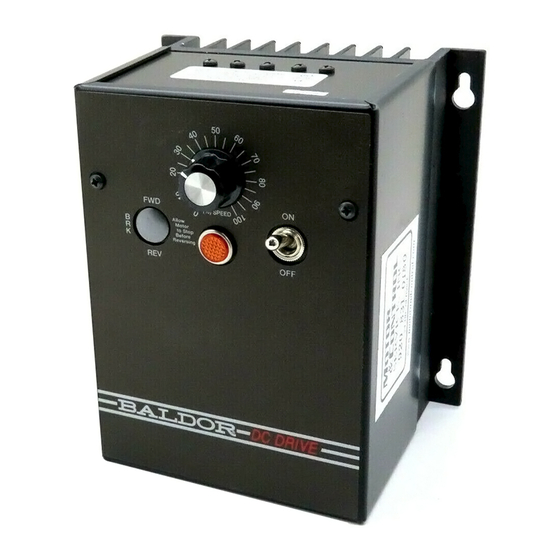
1.5 General Performance Specifications Table 1-5 outlines the general performance specifications of the BC140 / BC140-FBR control. Table 1-5 General Performance Specifications Factory Description Specification Setting Speed Range (Ratio) 50:1 — Armature Feedback Load Regulation (0 - Full Load, 50:1 Speed Range) (% —... - Page 16 Figure 1-1 Cover Layout Two (2) Cover Screws Recommended Tightening Torque: 5 lbs-in (6 kg-cm) Main Speed Potentiometer (%) SPEED Allow Motor to Stop Before Reversing On/Off AC Line Switch Pilot Light Optional Forward-Brake-Reverse Switch Note: See Section 6 for Voltage Select Switch (Located Under Cover)
- Page 17 Figure 1-2 Mechanical Specifications (Inches/[mm]) Two (2) Knockouts 5.00 for Standard [127] 3/4” Fittings 4.125 [105] 4.00 [102] 0.39 4X Ø [9.91] 5.63 7.00 Side View is Shown Dimensioned with [143] [178] Cover Installed and Optional Forward-Brake-Reverse Switch 0.35 4X Ø [5.08] Back View is Shown Dimensioned without Cover Installed...
-
Page 18: Quick Start
2. QUICK START IMPORTANT – You must read these simplified operating instructions before you proceed. These instructions are to be used as a reference only and are not intended to replace the detailed instructions provided herein. You must read the Safety Warnings and Cautions before proceeding. -
Page 19: Connections
2.1 Connections AC Line Connection: Connect the AC line input to Terminals L1 (Line Fuse) and L2, of the Barrier Terminal Block, as shown in Figure 2-2 and as described in Section 4. The Voltage Select Switch position must match the AC line input voltage. See Section 6. Note: See Table 4-2 for AC Line and Armature Fuse selection. -
Page 20: Ac Line Fusing
2.3 AC Line Fusing The control contains a built-in replaceable AC line fuse installed in the AC line fuse holder, as shown in Figure 2-3. Select the correct replacement AC Line Fuse, as described in Table 4-2. Note: If fuse blows, check for wrong connections and shorted or grounded motor. 2.4 Armature Fusing Select an armature fuse (supplied separately) and install in the armature fuse holder, as shown in Figure 2-3. -
Page 21: Voltage Select Switch
230 volts AC line input. See Table 1-2 and Section 11. 2.12 Optional Forward-Brake-Reverse Switch (BC144)* Used to dynamically brake the motor. It provides run/brake and forward-brake-reverse operations. See Table 1-2 and Section 12. * BC144 is factory installed on BC140-FBR model. - Page 22 Figure 2-3 Control Layout and Internal Connection Diagram ARMATURE FIELD LINE...
-
Page 23: Installation
3. INSTALLATION 3.1 Mounting The control is designed with a NEMA-1 / IP-40 enclosure for indoor use. It is recommended that the control be mounted vertically on a flat surface with adequate ventilation. Leave enough room below the control to allow for AC line and motor connections and any other connections that are required. A mounting template is included to facilitate mounting of the control. -
Page 24: Electrical Connections
4. ELECTRICAL CONNECTIONS See Table 4-1 for Barrier Terminal Block wire size and recommended tightening torque specifications. WARNING! READ SAFETY NOTICES BEFORE ATTEMPTING TO USE THIS CONTROL. DISCONNECT THE MAIN POWER BEFORE MAKING CONNECTIONS TO THE CONTROL. WARNING! TO AVOID ERRATIC OPERATION, DO NOT BUNDLE AC LINE AND MOTOR WIRES WITH WIRES FROM SIGNAL FOLLOWING, START/STOP CONTACTS, OR ANY OTHER SIGNAL WIRES. -
Page 25: Ac Line Connection
Table 4-1 Barrier Terminal Block Wire and Tightening Torque Specifications Maximum Wire Size (Cu) Recommended Maximum 90 – 130 Volt 180 Volt Tightening Motor Maximum Maximum DC Motors DC Motors Torque Current 50 Ft. 100 Ft. (Maximum HP) (Maximum HP) (Amps DC) lb-in kg-cm... - Page 26 Table 4-2 Armature and AC Line Fuse Chart Fuse Selection Approximate Motor Horsepower (AC Amps) Motor Current (Amps DC) 90VDC 180VDC Armature Line 1/100 1/50 1/50 1/25 1/30 1/15 0.33 1/20 1/10 0.75 1/15 1/12 0.85 1.25 1½ *With optional Auxiliary Heat Sink (Catalog No. BC143).
-
Page 27: Ac Line Fuse
4.4 AC Line Fuse The AC Line Fuse acts as a disconnect in case of a catastrophic failure. If the AC Line Fuse blows, the control is miswired, the motor is shorted or grounded, or the control is defective. Note: Fuse each AC line conductor that is not at ground potential. 4.5 Armature Fuse The Armature Fuse acts as a diagnostic indicator. - Page 28 Table 4-3 Plug-In Horsepower Resistor and Armature Fuse Kit Information ® Plug-In Horsepower Resistor ® Motor Horsepower Armature Fuse Kit Approximate Plug-In Armature Motor Current Armature Armature Horsepower Fuse (Amps DC) Voltage Voltage Resistor Catalog No. ® Rating 90 – 130 Volts DC 180 Volts DC Value (Amps)
-
Page 29: Permanent Magnet (Pm) Motor Armature Connection
4.7 Permanent Magnet (PM) Motor Armature Connection Connect the motor armature positive lead (+) to Terminal “A+” and negative lead (-) to Terminal “A-”, on the Barrier Terminal Board, as shown in Figure 2-3. Be sure the correct Plug-In Horsepower Resistor ®... -
Page 30: Important Application Information
PRODUCT. READ SAFETY NOTICES. 5.1 Motor Type The BC140 / BC140-FBR is designed for permanent magnet (PM) and Shunt Wound DC motors. Controls operated on 115 Volt AC line input are designed for 90 Volt SCR rated motors. Controls operated on 230 Volt AC line input are designed for 180 and 90 Volt (step-down) SCR rated motors. Use of higher voltage motors will result in a reduction of the available maximum speed. -
Page 31: Limitation In Use
CAUTION! Contact your local Baldor District Office before using this control on constant horsepower applications such as saws and drill presses. Do not use this control in an explosive atmosphere. Be sure the BC140 / BC140-FBR is used within its ratings. Follow all instructions carefully. -
Page 32: Setting The Voltage Select Switch
6. SETTING THE VOLTAGE SELECT SWITCH WARNING! READ ALL SAFETY NOTICES BEFORE ATTEMPTING TO OPERATE THE CONTROL OR SEVERE INJURY OR DEATH CAN RESULT. FAILURE TO FOLLOW THE WARNINGS AND CAUTIONS, MAY RESULT IN ELECTRIC SHOCK, FIRE OR EXPLOSION. The Voltage Select Switch is located under the cover and must be set before applying power to the control. See Figure 6-1. -
Page 33: Trimpot Adjustments
7. TRIMPOT ADJUSTMENTS The control contains trimpots which have been factory set for most applications. Figure 2-3 illustrates the location of the trimpots and their approximate factory set positions. Some applications may require readjustment of the trimpots in order to set the control for a specific requirement. See Table 1-5 for range and factory setting of all trimpots. -
Page 34: Deceleration Trimpot (Decel)
7.2 Deceleration Trimpot (DECEL) The DECEL Trimpot controls the amount of rampdown time when the Main Speed Potentiometer is adjusted to a lower speed. The DECEL Trimpot is factory set to 2 seconds, which is the amount of time it will take for the motor to decelerate from full speed to zero speed. To increase the deceleration time, rotate the DECEL Trimpot clockwise. -
Page 35: Maximum Speed Trimpot (Max)
7.4 Maximum Speed Trimpot (MAX) The MAX Trimpot sets the maximum speed of the motor when the Main Speed Potentiometer is set fully clockwise. The MAX Trimpot is factory set to 100% of base motor speed. To increase the maximum speed, rotate the MAX Trimpot clockwise. -
Page 36: Current Limit Trimpot (Cl)
7.5 Current Limit Trimpot (CL) The CL Trimpot is used to limit the maximum current (torque) to the motor. The CL also protects the control from excessive current during startup. The CL Trimpot is factory set to 150% of the full load current rating of the motor. - Page 37 To Recalibrate the CL Trimpot: Disconnect the AC power and connect a DC ammeter in series with either motor armature lead. If only an AC ammeter is available, connect it in series with either AC line input lead. Set the Main Speed Potentiometer to approximately 30% – 50% clockwise position. Set the CL Trimpot fully counterclockwise.
-
Page 38: Ir Compensation Trimpot (Ir)
7.6 IR Compensation Trimpot (IR) The IR Trimpot sets the amount of compensating voltage required to keep the motor speed constant under varying loads. If the load does not vary substantially, the IR Trimpot may be set to a minimum level (approximately 1/4 of full clockwise rotation). - Page 39 To Recalibrate the IR Trimpot: Set the IR Trimpot to approximately 25% rotation. Run the motor unloaded at approximately 1/3 speed and record the RPMs. Run the motor with the maximum load and adjust the IR Trimpot so that the motor speed under load equals the unloaded speed recorded in step 2.
-
Page 40: Operation
8. OPERATION WARNING! READ SAFETY NOTICES BEFORE OPERATING THIS CONTROL OR SEVERE INJURY OR DEATH CAN RESULT. 8.1 With no AC power applied and the On/Off AC Line Switch set to the “OFF” position, remove the front cover by unscrewing the two cover screws. See Figure 1-1. 8.2 Set the Voltage Select Switch to the correct position, corresponding to the AC line input voltage. -
Page 41: Diagnostics Leds And Pilot Lights
9. DIAGNOSTIC LEDS AND PILOT LIGHT The BC140 / BC140-FBR has PC board mounted LEDs, to display the control’s operational status and a panel-mounted Pilot Light. See Figure 2-3 for the location of the LEDs. 9.1 Power On (PWR ON) LED and Pilot Light When the AC power is applied to the control and the On/Off AC Line Switch is set “ON”, the PWR... -
Page 42: Troubleshooting
10. TROUBLESHOOTING Table 10-1 is a troubleshooting guide for controls without the optional Forward-Brake Reverse Switch installed. Table 10-2 is a troubleshooting guide for controls with the Forward-Brake-Reverse Switch installed. Both tables provide information on symptoms, their possible causes, and suggested corrective actions. - Page 43 Table 10-1 provides information on symptoms, possible causes, and the suggested corrective action for controls without optional forward-brake-reverse switch installed. Table 10-1 Troubleshooting Guide for Controls without Optional Forward-Brake-Reverse Switch Installed Symptom Possible Cause Suggested Corrective Action On/Off AC Line Switch in “Off” Set On/Off Switch to “On”...
- Page 44 Table 10-1 Troubleshooting Guide for Controls without Optional Forward-Brake-Reverse Switch Installed (Continued) Symptom Possible Cause Suggested Corrective Action Overload condition. Remove overload. Install the correct Plug-In Incorrect Plug-In Horsepower Horsepower Resistor . See Table ® Resistor ® 4-3. CL and/or IR Trimpots may be set Readjust the CL and/or IR Trimpots, Erratic motor performance.
- Page 45 Table 10-2 provides information on symptoms, possible causes, and the suggested corrective action for controls with optional forward-brake-reverse switch installed. Table 10-2 Troubleshooting Guide for Controls with Optional Forward-Brake-Reverse Switch Installed Symptom Possible Cause Suggested Corrective Action Faulty wiring or loose connections Correct the connections.
-
Page 46: Optional Auxiliary Heat Sink (Catalog No. Bc143)
11. OPTIONAL AUXILIARY HEAT SINK (CATALOG NO. BC143) The optional Auxiliary Heat Sink (Catalog No. BC143) is used to increase the rating of the control. See Table 1-3. The control is mounted on the four (4) holes with four (4) mounting screws (supplied), as shown in Figure 11-1. -
Page 47: Optional Forward-Brake-Reverse Switch (Catalog No. Bc144)
See the installation instructions MN1372, provided with the Forward-Brake-Reverse Switch kit for detailed information on mounting and connections. Figure 12-1 shows the connections of the Forward-Brake-Reverse Switch to the speed control and the Barrier Terminal Block. * BC144 is factory installed on BC140-FBR model. Figure 12-1 Optional Forward-Brake-Reverse Switch Connections... - Page 48 NOTES: _____________________________________________________________________________________________ _____________________________________________________________________________________________ _____________________________________________________________________________________________ _____________________________________________________________________________________________ _____________________________________________________________________________________________ _____________________________________________________________________________________________ _____________________________________________________________________________________________ _____________________________________________________________________________________________ _____________________________________________________________________________________________ _____________________________________________________________________________________________ _____________________________________________________________________________________________ _____________________________________________________________________________________________ _____________________________________________________________________________________________ _____________________________________________________________________________________________...
-
Page 49: Limited Warranty
LIMITED WARRANTY For a period of 2 years from date of original purchase, BALDOR will repair or replace without charge controls which our examination proves to be defective in material or workmanship. This warranty is valid if the unit has not been tampered with by unauthorized persons, misused, abused, or improperly installed and has been used in accordance with the instructions and/ or ratings supplied. -
Page 50: Baldor District Offices
Baldor District Offices - United States Locations UNITED STATES FLORIDA MASSACHUSETTS NORTH CAROLINA PITTSBURGH BOSTON TAMPA/PUERTO RICO/ GREENSBORO 159 PROMiNENCE DRivE ARIZONA VIRGIN ISLANDS 6 PULLMAN STREET NEW kENSiNgTON, PA 15068 1220 ROTHERWOOD ROAD PHOENIX 3906 EAST 11TH AvENUE WORCESTER, MA 01606... - Page 51 Baldor District Offices - International Locations KOREA SWITZERLAND INTERNATIONAL SALES AUSTRALIA DiESELSTRASSE 22 RM#1715, SUSEO TOWER, 725, POST FACH 73 FORT SMITH, AR UNiT 3, 6 STANTON ROAD kiRCHHEiM, D-85551 SUSEO-DONg, gANgNAM-gU, SCHUETZENSTRASSE 59 P.O. BOX 2400 SEvEN HiLLS, NSW 2147,...
- Page 52 P.O. Box 2400, Fort Smith, AR 72902-2400 U.S.A., Ph: (1) 479.646.4711, Fax (1) 479.648.5792, International Fax (1) 479.648.5895 Baldor - Dodge 6040 Ponders Court, Greenville, SC 29615-4617 U.S.A., Ph: (1) 864.297.4800, Fax: (1) 864.281.2433 www.baldor.com © Baldor Electric Company All Rights Reserved. Printed in USA. MN703 (A40244B) - Rev D - 11/11...