Table of Contents
Advertisement
Published 08/14
This Operator's Manual is an
integral part of the safe operation
of this machine and must be
maintained with the unit at all
times. READ, UNDERSTAND, and
FOLLOW
Operation Instructions contained
in this manual before operating
the equipment. C01-Cover_B
®
BUSH HOG
2501 Griffin Ave.
Selma, AL 36703
334-874-2700
www.bushhog.com
OPERATOR'S MANUAL
the
Safety
© 2014 Alamo Group Inc.
ROTARY CUTTER
Important
Operating
and Safety Instructions
are found in the Mower
Safety Video that can
and
be instantly accessed
on
the
internet
www.algqr.com/bve
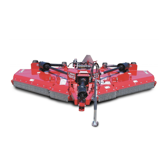
1812
FLEX-WING
Part No. 50074697
at:
$0.00
Advertisement
Table of Contents

Related Manuals for Bush Hog 1812


Summary of Contents for Bush Hog 1812
- Page 1 1812 FLEX-WING ROTARY CUTTER Published 08/14 Part No. 50074697 OPERATOR’S MANUAL This Operator's Manual is an integral part of the safe operation Important Operating of this machine and must be and Safety Instructions maintained with the unit at all are found in the Mower times.
- Page 3 In order to reduce accidents and enhance the safe operation of mowers, Bush Hog, in cooperation with other industry manufacturers has developed the AEM/FEMA Industrial and Agricultural Mower Safety Practices video and guide book. The video will familiarize and instruct mower-tractor operators in safe practices when using industrial and agricultural mowing equipment.
- Page 4 Bush Hog will provide one (1) AEM Mower Safety Practices Video Please Send Me: VHS Format – AEM/FEMA Mower Operator Safety Video DVD Format – AEM/FEMA Mower Operator Safety Video Mower Operator’s Manual AEM Mower Operator’s Safety Manual Requester Name:___________________________________Phone:...
- Page 5 A Manual canister is provided on the implement where this manual can be properly stored. If you lose or damage this manual a free replacement manual can be obtained from an authorized Bush Hog dealer or by down loading the manual from the Bush Hog website www.bushhog.com...
- Page 6 DEALER to CUSTOMER Pre-Delivery/ Operation Instructions Dealer should inform the Purchaser of this product of Warranty terms, provisions, and procedures that are applicable.Dealer should inform Purchaser to review the contents of the Operator’s Manual including safety equipment, safe operation, and maintenance, to review the Safety Signs on the implement (and tractor if possible), and of Purchaser’s responsibility to train his/her operators’s in safe operation procedures.
-
Page 7: Table Of Contents
PARTS INFORMATION ............................ 1-14 Decal Location ..............................1-15 Decal Description .............................. 1-17 Federal Laws and Regulations ......................... 1-25 INTRODUCTION SECTION....................2-1 Equipment Specifications 1812........................... 2-3 KEY OPERATION POINTS ..........................2-4 Operating Noise Level/Sound Pressure......................2-4 ASSEMBLY SECTION ......................3-1 DEALER SET-UP INSTRUCTIONS........................3-2 ASSEMBLY................................. - Page 8 CONNECTING THE MOWER TO THE TRACTOR .................... 4-8 Connecting Mower Tongue to the Tractor ......................4-9 Connecting Mower Hydraulic Lines to the Tractor ....................4-9 SETTING THE MOWER ........................... 4-11 Setting Deck Height ............................4-11 Setting Deck Pitch............................. 4-12 DRIVELINE ATTACHMENT ..........................4-13 Driveline Length Check .............................
-
Page 9: Safety Section
SAFETY SECTION Safety Section 1-1 © 2014 Alamo Group Inc. -
Page 10: General Safety Instructions And Practices
NOTE: If you want a translation of this safety section in one of the following Languages, please contact: Translations at 1502 E. Walnut Street Seguin, TX 78155; Fax: (830) 372-9529; Safety Section Translations are available in Spanish, Portuguese, French, German, Russian. PN GS01 1812 08/14 Safety Section 1-2 © 2014 Alamo Group Inc. -
Page 11: Operator Safety
DO NOT EXCEED IMPLEMENT RATED PTO SPEED • AVOID exceeding rated PTO speeds that may result in broken drivelines or blade failures. SAFETY SIGNS: • REPLACE missing, damaged or unreadable safety signs immediately. PN OS01 1812 08/14 Safety Section 1-3 © 2014 Alamo Group Inc. -
Page 12: Crushing Hazards
ATTACH hoses to tractor. • FILL Wing Cylinders with oil. (Refer to Instructions in Operation Section) • KEEP bystanders away before operating wings. • LOWER WINGS slowly and carefully. PN CH01 1812 08/14 Safety Section 1-4 © 2014 Alamo Group Inc. -
Page 13: Connecting Or Disconnecting Implement Safety
KEEP bystanders clear of area before operating wings. • LOWER WINGS slowly and carefully. DO NOT connect the Mower to a tractor with the PTO directly connected to the Tractor transmission. PN CD01 1812 08/14 Safety Section 1-5 © 2014 Alamo Group Inc. -
Page 14: Thrown Objects Hazards
3. INSPECT AREA thoroughly before mowing to REMOVE potential THROWN OBJECT HAZARDS, 4. NEVER ALLOW BLADES to CONTACT SOLID OBJECTS like wire, rocks, post, curbs, guardrails, or ground while mowing. PN TO01 1812 08/14 Safety Section 1-6 © 2014 Alamo Group Inc. - Page 15 STOP mowing when EXCESSIVE VIBRATION occurs: 1. STOP PTO and tractor ENGINE. 2. INSPECT mower for vibration source. 3. REPLACE any damage parts and bent or damaged BLADES. PN TO01-X 1812 08/14 Safety Section 1-7 © 2014 Alamo Group Inc.
-
Page 16: Run Over Hazards
ONLY mount or dismount when tractor and moving parts are stopped. • STOP ENGINE AND PTO, engage parking brake, lower implement, allow all moving parts to stop and remove key before dismounting from tractor. PN RO01 1812 08/14 Safety Section 1-8 © 2014 Alamo Group Inc. -
Page 17: Pto Entanglement Hazards
DO NOT USE PTO ADAPTER. Using a PTO adapter can cause excessive vibration, thrown objects, blade and implement failures by doubling operating speed. Increased working length exposing unshielded driveline areas. PN PE01 1812 08/14 Safety Section 1-9 © 2014 Alamo Group Inc. -
Page 18: Mower Blade Contact Hazards
KEEP hands and body AWAY from pin holes and nozzles ejecting hydraulic fluid. • Hydraulic fluid may cause gangrene if not surgically removed immediately by a doctor familiar with this form of injury. PN HP01 1812 08/14 Safety Section 1-10 © 2014 Alamo Group Inc. -
Page 19: Electrical & Fire Hazard
ADJUST SLIP CLUTCHES to avoid excessive slippage and clutch plate heating. • CLEAR any grass clippings or debris buildup around mower drivelines, slip clutches, and gearboxes. • SHUT OFF ENGINE while refueling. PN EF01 1812 08/14 Safety Section 1-11 © 2014 Alamo Group Inc. -
Page 20: Transporting Hazards
TURN ON tractor FLASHING WARNING LIGHTS. • ALLOW clearance for implement swing while turning. KEEP all raised wings at 10 feet or greater distance from all power lines and overhead obstructions. PN TH01 1812 08/14 Safety Section 1-12 © 2014 Alamo Group Inc. -
Page 21: Hazards With Maintenance Of Implement
• Battery posts, terminals and related accessories contain lead and lead compounds, chemicals known to the state of California to cause cancer, birth defects or other reproductive harm. PN HM01 1812 08/14 Safety Section 1-13 © 2014 Alamo Group Inc. -
Page 22: Parts Information
PARTS INFORMATION PARTS INFORMATION Bush Hog mowers use balanced and matched system components for blade carriers, blades, cuttershafts, knives, knife hangers, rollers, drivetrain components, and bearings. These parts are made and tested to Bush Hog specifications. Non-genuine "will fit" parts do not consistently meet these specifications. The use of “will fit”... -
Page 23: Decal Location
SAFETY Decal Location NOTE: Bush Hog supplies safety decals on this product to promote safe operation. Damage to the decals may occur while in shipping, use, or reconditioning. Bush Hog cares about the safety of its customers, operators, and bystanders, and will replace the safety decals on this product in the field, free of charge (Some shipping and handling charges may apply). - Page 24 DANGER Crushing Hazard, Transport Latch D565 DANGER Crushing Hazard, Wing Drop D587 INSTRUCT Lubrication Decal D614 DANGER Thrown Objects D559 WARNING Genuine Bush Hog Parts 50031212 REFLECT Amber Reflector D813 DANGER Multi-Language D546 DANGER Guard Missing 50031214 REFLECT Red Reflector...
-
Page 25: Decal Description
SAFETY Decal Description 1812 08/14 Safety Section 1-17 © 2014 Alamo Group Inc. - Page 26 SAFETY 1812 08/14 Safety Section 1-18 © 2014 Alamo Group Inc.
- Page 27 SAFETY 1812 08/14 Safety Section 1-19 © 2014 Alamo Group Inc.
- Page 28 SAFETY 1812 08/14 Safety Section 1-20 © 2014 Alamo Group Inc.
- Page 29 SAFETY 1812 08/14 Safety Section 1-21 © 2014 Alamo Group Inc.
- Page 30 SAFETY 1812 08/14 Safety Section 1-22 © 2014 Alamo Group Inc.
- Page 31 SAFETY 1812 08/14 Safety Section 1-23 © 2014 Alamo Group Inc.
- Page 32 SAFETY 1812 08/14 Safety Section 1-24 © 2014 Alamo Group Inc.
-
Page 33: Federal Laws And Regulations
Some regulations specify that no one under the age of 16 may operate power machinery. It is your responsibility to know what these regulations are in your own area or situation. (Refer to U.S. Dept. of Labor, Employment Standard Administration, Wage & Home Division, Child Labor Bulletin #102.) 1812 08/14 Safety Section 1-25 © 2014 Alamo Group Inc. -
Page 35: Introduction Section
INTRODUCTION SECTION Introduction Section 2-1 © 2014 Alamo Group Inc. - Page 36 INTRODUCTION We are pleased to have you as a Bush Hog customer. Your Rotary Cutter has been carefully designed with care and built with quality materials by skilled workers to give maximum service with minimum down time. This manual is provided to give you the necessary operating and maintenance instructions for keeping your rotary cutter in top operating condition.
-
Page 37: Equipment Specifications 1812
The Bush Hog Model 1812 Flex Wing Rotary Cutter is designed primarily for weed, grass, and brush to 1-1/2" diameter and consists of a center unit with two variable position wings together having a cutting width of 12 feet. -
Page 38: Key Operation Points
* WARRANTY LIMITATIONS - GEARBOX A. Users' Gearboxes may be rebuilt by Bush Hog or replaced by new or rebuilt Gearboxes at the option of Bush Hog. 1. ONE-YEAR (12 months) LIMITED WARRANTY** on the DRIVELINE components provided they have been properly maintained†... -
Page 39: Limited Warranty
2. If the unit has been subjected to misapplication, abuse, misuse, negligence, fire or other accident. 3. If parts not made or supplied by Bush Hog have been used in connection with the unit, if, in the sole judgment of Bush Hog such use affects its performance, stability or reliability. -
Page 41: Assembly Section
ASSEMBLY SECTION Assembly Section 3-1 © 2012 Alamo Group Inc. -
Page 42: Dealer Set-Up Instructions
The unit comes with all axles and axle arms attached and tires on the center unit. Wing tires will need to be attached to the wing axle arms and if the unit has dual wheel center axle arms, two tires will be assembled to these axle arms. 1812 08/14 Assembly Section 3-2 © 2012 Alamo Group Inc. -
Page 43: Tongue
Connect the opposite end to the center axle weldment using the pin and cotter pins shipped in the leveling rod assembly. Connection at Tongue Connection at Axle 1812 08/14 Assembly Section 3-3 © 2012 Alamo Group Inc. -
Page 44: Tires And Wheels
1” x 4” bolts, flatwashers, and nuts. 3. There are three types of wheels available for this machine. The airplane tires will have a larger diameter than the laminated tire. 1812 08/14 Assembly Section 3-4 © 2012 Alamo Group Inc. - Page 45 INJURY. Do not exceed 20 M.P.H. on Airplane or Rib Implement Tires. Maximum airplane tire inflation pressure is 50 PSI, minimum inflation pressure is 20 PSI. Inflate ribbed implement tires to manufacturer rated PSI as shown on the tire sidewall. 1812 08/14 Assembly Section 3-5 © 2012 Alamo Group Inc.
-
Page 46: Hydraulics
Consult your tractor dealer to determine which type system your tractor has. Use tie straps to secure hydraulic hoses to leveling rod. Failure to match valve to tractor hydraulic system by using incorrect plug will cause damage to tractor. 1812 08/14 Assembly Section 3-6 © 2012 Alamo Group Inc. - Page 47 ASSEMBLY 1812 08/14 Assembly Section 3-7 © 2012 Alamo Group Inc.
-
Page 48: Driveline Attachment To Implement
Tighten tapered pin retaining nut to 30 ft. lbs. Install one roll pin through yoke and stub shaft. 1812 08/14 Assembly Section 3-8... -
Page 49: Wing Driveline
Many of the equipment components are HEAVY (60 lbs or greater) and Special Lifting Procedures are recommended. Use lifting assistance such as mechanical assistance, two people, and proper lifting techniques when connecting or installing the driveshaft to reduce the possibility of back injuries. 1812 08/14 Assembly Section 3-9 © 2012 Alamo Group Inc. -
Page 51: Operation Section
OPERATION SECTION Operation Section 4-1 © 2012 Alamo Group Inc. - Page 52 BUSH HOG 1812 ROTARY MOWER OPERATION INSTRUCTIONS Bush Hog rotary mowers are manufactured with quality material by skilled workers. These mowers are designed to cut grass, weeds, small brush and other vegetative material up to 2” diameter in areas such as pastures and along highway right-of-ways.
-
Page 53: Operator Requirements
Serious injury or death to the operator or others could result if the operator is under the influence of drugs or alcohol. (SG-27) 1812 08/14 Operation Section 4-3 © 2012 Alamo Group Inc. -
Page 54: Tractor Requirements
Never operate the tractor PTO with the PTO master shield missing or in the raised position. OPS-U- 0004 1812 08/14 Operation Section 4-4 © 2012 Alamo Group Inc. -
Page 55: Tractor Horsepower
For most mowing conditions, the 1812 mower requires a tractor with a minimum of 50 HP. Operating the mower with a tractor that does not have adequate power may damage the tractor engine. Exceeding 75 HP may cause mower damage by overpowering the unit in heavy cutting conditions. -
Page 56: Tire Spacing
OPS-U- 0007 Do not mount or dismount the Tractor while the tractor is moving. Mount the Tractor only when the Tractor and all moving parts are completely stopped. (SG-12) 1812 08/14 Operation Section 4-6 © 2012 Alamo Group Inc. -
Page 57: Boarding The Tractor
Place the tractor shift lever into a low range or parking gear to prevent the tractor from rolling. Never dismount a Tractor that is moving or while the engine is running. Operate the Tractor controls from the tractor seat only. (SG-9) 1812 08/14 Operation Section 4-7 © 2012 Alamo Group Inc. -
Page 58: Starting The Tractor
Always shut the Tractor completely down, place the transmission in park, and set the parking brake before you or anyone else attempts to connect or disconnect the Implement and Tractor hitches. (S3PT-15) 1812 08/14 Operation Section 4-8 © 2012 Alamo Group Inc. -
Page 59: Connecting Mower Tongue To The Tractor
When connecting the mower hydraulic lines, keep hoses, quick couplers, and swivels free of contamination. Never leave a disconnected hose end open and cap the tractor hydraulic outlet ports when not in use. If the 1812 08/14 Operation Section 4-9... - Page 60 Ensure wings are entirely supported by the cylinders before removing the transport lock pins. NEVER drive out bar pins and NEVER remove bars that have tension on them. 1812 08/14 Operation Section 4-10 © 2012 Alamo Group Inc.
-
Page 61: Setting The Mower
It may be necessary to use wing lift cylinder to relieve pressure from the linkage retaining pin. Tighten jam nut. 1812 08/14 Operation Section 4-11 © 2012 Alamo Group Inc. -
Page 62: Setting Deck Pitch
Adjust the leveling rods the same amount and maintain equal tension in the rods. Improper adjustment may cause rods to snap or bend. Retighten the jamnuts after the deck pitch has been set. OPS-U-0041_A 1812 08/14 Operation Section 4-12 © 2012 Alamo Group Inc. -
Page 63: Driveline Attachment
At its farthest operating extension, a minimum profile engagement of 6” must be maintained for a Constant Velocity (CV) tube type driveline and a minimum engagement of 6” for non-CV solid shaft drivelines. 1812 08/14 Operation Section 4-13 © 2012 Alamo Group Inc. - Page 64 NOTE: If the driveline cannot be shortened and still maintain the required profile engagement, the operator must be made aware of terrain conditions and avoid situations which pose a potential problem to avoid damaging the driveline or move drawbar to 16” or 20” position for required clearance. OPS-R-0005_O 1812 08/14 Operation Section 4-14 © 2012 Alamo Group Inc.
-
Page 65: Constant Velocity (Cv) Driveline
Position the mower at multiple angles and perform the above procedure. Determine the sharpest turning radius that maintains a safe operating angle and note this position to the operator. OPS-R-0006_B 1812 08/14 Operation Section 4-15 © 2012 Alamo Group Inc. -
Page 66: Pre-Operation Inspection And Service
Make sure all pins have cotter pins and washers. Serious injury may occur from not maintaining this machine in good working order. (SG-21) 1812 08/14 Operation Section 4-16 © 2012 Alamo Group Inc. -
Page 67: Tractor Pre-Operation Inspection/Service
Engine coolant level and condition • Power brake fluid level • Power steering fluid level • Fuel condition and level • Sufficient lubrication at all lube points • Air filter condition OPS-U-0030 1812 08/14 Operation Section 4-17 © 2012 Alamo Group Inc. -
Page 68: Mower Pre-Operation Inspection/Service
Ensure the manual canister is secured to the equipment with the operator’s manual inside. • Ensure all safety signs are in place and legible. Replace missing, damaged, and illegible decals. OPS-U- 0011 1812 08/14 Operation Section 4-18 © 2012 Alamo Group Inc. - Page 69 • Ensure the driveline slip clutches are properly adjusted and the friction plates are not frozen together. Reference the Maintenance Section for proper slip clutch maintenance. OPS-R- 0010 1812 08/14 Operation Section 4-19 © 2012 Alamo Group Inc.
- Page 70 DO NOT use your hands to check for oil leaks. Use a piece of heavy paper or cardboard to check for hydraulic oil leaks. OPS-R-0013_J 1812 08/14 Operation Section 4-20 © 2012 Alamo Group Inc.
- Page 71 Check the condition of the wing hinge pins. • Check the condition of the mower axle suspension spring. • Inspect mower tire condition, wheel bearings, and lug nut torque. OPS-R-0014_G 1812 08/14 Operation Section 4-21 © 2012 Alamo Group Inc.
-
Page 72: Cutting Component Inspection
OPERATION 9.3 Cutting Component Inspection Inspect blade pan and blade assembly for the following: OPS-U-0031 1812 08/14 Operation Section 4-22 © 2012 Alamo Group Inc. - Page 73 Failure to replace abnormally worn blades may lead to catastrophic failure of the blades and ejection of the broken part with tremendous force which may cause serious bodily injury or death. OPS-U-0032 1812 08/14 Operation Section 4-23 © 2012 Alamo Group Inc.
-
Page 74: Blade Bolt Inspection
Failure to replace abnormally worn blade bolts may lead to catastrophic failure of the blades and ejection of the broken part which may cause serious bodily injury or death. Always replace Blade Bolts with new bolts whenever replacing the Blades. OPS-U-0037 1812 08/14 Operation Section 4-24 © 2012 Alamo Group Inc. - Page 75 Blades are not chipped, cracked or bent Blade bolts are tight Wheel lug nuts are tight Transport locks are in good condition Make____________________ Shift ____________________ Operator’s Signature: DO NOT OPERATE an UNSAFE TRACTOR or MOWER 1812 08/14 Operation Section 4-25 © 2012 Alamo Group Inc.
- Page 76 The engine coolant fluid level is full The radiator is free of debris The air filter is in good condition Operator’s Signature:___________________________________________________ DO NOT OPERATE an UNSAFE TRACTOR or IMPLEMENT 1812 08/14 Operation Section 4-26 © 2012 Alamo Group Inc.
-
Page 77: Driving The Tractor And Implement
When operating in traffic always use the Tractor’s flashing warning lights and reduce your speed. Be aware of traffic around you and watch out for the other guy. (SG-19) 1812 08/14 Operation Section 4-27 © 2012 Alamo Group Inc. -
Page 78: Starting The Tractor
(wings) and extend (center). Only operate the mower with both wings fully lowered, NEVER operate the mower with a raised wing. Wait until the blades are at a complete stop before raising wings. OPS-R-0015 1812 08/14 Operation Section 4-28 © 2012 Alamo Group Inc. -
Page 79: Transport Position
This will give the mower more stability and prevent the opposite wing from raising. DO NOT operate the mower with the valves in the detent position for extended periods of time to prevent deck frame damage. OPS-R-0017_G 1812 08/14 Operation Section 4-29 © 2012 Alamo Group Inc. -
Page 80: Driving The Tractor And Cutter
Use extreme caution when operating on steep slopes. Keep the tractor in a low gear when going downhill. DO NOT coast or free-wheel downhill. OPS-R-0018 Crossing Ditches and Steep Inclines 1812 08/14 Operation Section 4-30 © 2012 Alamo Group Inc. - Page 81 When crossing such terrain, the implement should be fully lowered for a lower center of gravity and added stability. OPS-R-0021 1812 08/14 Operation Section 4-31 © 2012 Alamo Group Inc.
-
Page 82: Operating The Tractor And Implement
Stop mowing immediately if blades strike a foreign object. Repair all damage and make certain rotor or blade carrier is balanced before resuming mowing. (SGM-05) 1812 08/14 Operation Section 4-32 © 2012 Alamo Group Inc. -
Page 83: Foreign Debris Hazards
If a bystander comes within 300 feet of the tractor while the mower is being operated, stop the tractor at once, idle the engine and disengage the PTO. Do not engage the PTO again until all bystanders are well past the 300 foot distance. OPS-R-0024 1812 08/14 Operation Section 4-33 © 2012 Alamo Group Inc. -
Page 84: Engaging The Power Take Off (Pto)
Do not put hands or feet under mower decks. Blade Contact can result in serious injury or even death. Stay away until all motion has stopped and the decks are securely blocked up. (SGM-09) 1812 08/14 Operation Section 4-34 © 2012 Alamo Group Inc. -
Page 85: Pto Rpm And Ground Speed
When mowing in reverse, operate the tractor and mower at a reduced ground speed to ensure tractor and mower control is maintained 1812 08/14 Operation Section 4-35 © 2012 Alamo Group Inc. - Page 86 -Never allow clippings or debris to collect near drivelines, slip clutches, and gearboxes. Periodically shut down the Tractor and Mower and clean clippings and collected debris from the mower deck. (SGM-12) 1812 08/14 Operation Section 4-36 © 2012 Alamo Group Inc.
- Page 87 Stay alert and watch for trees, low hanging limbs, power lines, and other overhead obstacles and solid ground objects while you are operating. Use care to avoid hitting these items OPS-R-0028 1812 08/14 Operation Section 4-37 © 2012 Alamo Group Inc.
- Page 88 Always avoid operating the mower at a height or position which may cause the blades to contact the ground. Cutting into the berm or edge of the ditch will cause abnormal and accelerated blade wear and possible blade component failure. OPS-R-0029 1812 08/14 Operation Section 4-38 © 2012 Alamo Group Inc.
-
Page 89: Right Of Way (Highway) Mowing
Mower sections or wings are adjusted to be close and parallel to ground without exposing blades. • MOWING AREA has been inspected and foreign materials and debris have been removed. • PASSERSBY are inside enclosed vehicle. OPS-U-0040 1812 08/14 Operation Section 4-39 © 2012 Alamo Group Inc. -
Page 90: Shutting Down The Implement
Always shut the Tractor completely down, place the transmission in park, and set the parking brake before you or anyone else attempts to connect or disconnect the Implement and Tractor hitches. (S3PT-15) 1812 08/14 Operation Section 4-40 © 2012 Alamo Group Inc. - Page 91 After the driveline has been removed from the tractor, place the PTO master shield back in the operating position. OPS-R-0031 1812 08/14 Operation Section 4-41 © 2012 Alamo Group Inc.
-
Page 92: Mower Storage
By using good judgement and following safe transport procedures, the possibility of accidents while moving between locations can be substantially minimized. OPS-U- 0017 1812 08/14 Operation Section 4-42 © 2012 Alamo Group Inc. - Page 93 Use extreme caution and avoid hard applications of the tractor brakes when towing heavy loads at road speeds. Never tow the implement at speeds greater than 20 MPH (32 kph). OPS-U- 0018 1812 08/14 Operation Section 4-43 © 2012 Alamo Group Inc.
-
Page 94: Tire And Wheels
Secure the center section at a safe transport height by placing additional stroke control spacers on the center axle cylinder and then lower the mower. Secure the mower wings in the raised position with the transport lock pins. OPS-R-0036_E 1812 08/14 Operation Section 4-44 © 2012 Alamo Group Inc. - Page 95 Consult an authorized tractor dealer for lighting kits and modifications available to upgrade the lighting on older tractor models. OPS-U- 0021 1812 08/14 Operation Section 4-45 © 2012 Alamo Group Inc.
-
Page 96: Lighting & Marking Of Agricultural Equipment - Ansi/Ase Standard 279.16
It is highly recommended that a 7 Pin receptacle be installed by a qualified technician on models that do not have a receptacle in order to safely transport this equipment on public roadways. 1812 08/14 Operation Section 4-46 © 2012 Alamo Group Inc. -
Page 97: Hauling The Tractor And Implement
If during transport a hard braking, sharp turning, or swerving action was performed, stop at the next safe location to inspect the security of the load. 1812 08/14 Operation Section 4-47 © 2012 Alamo Group Inc. -
Page 98: Trouble Shooting Guide
Repair clutch per maintenance plates warped. section of manuals. Too much power for clutch. Reduce ground speed and material intake. Oil on facings. Replace facings. Friction facings glazed. Clean with emery cloth. 1812 08/14 Operation Section 4-48 © 2012 Alamo Group Inc. - Page 99 Material Distribution rear. (Refer to the "Operation Section- Setting the Mower- Setting Deck Height”) Excessive ground speed Reduce ground speed. Conditions too wet. Wait for conditions to dry. Reduce ground speed. 1812 08/14 Operation Section 4-49 © 2012 Alamo Group Inc.
-
Page 101: Maintenance Section
MAINTENANCE SECTION Maintenance Section 5-1 ©2014 Alamo Group Inc. -
Page 102: Hazards With Maintenance Of Implement
• Battery posts, terminals and related accessories contain lead and lead compounds, chemicals known to the state of California to cause cancer, birth defects or other reproductive harm. PN HM02 1812 08/14 Maintenance Section 5-2 ©2014 Alamo Group Inc. -
Page 103: Parts Information
PARTS INFORMATION PARTS INFORMATION Bush Hog mowers use balanced and matched system components for blade carriers, blades, cuttershafts, knives, knife hangers, rollers, drivetrain components, and bearings. These parts are made and tested to Bush Hog specifications. Non-genuine "will fit" parts do not consistently meet these specifications. The use of “will fit”... - Page 104 Center Gearbox 8 Hours Divider Gearbox 8 Hours Tailwheel Wheel Hubs 120 Hours Axe Pivot 8 Hours Tongue Pivot 8 Hours Miscellaneous Wing Turnbuckle 40 Hours Leveling Rod Links 40 Hours 1812 08/14 Maintenance Section 5-4 ©2014 Alamo Group Inc.
-
Page 105: Center & Wing Gearboxes
Do not over-fill. If gearboxes are filled above the Dipstick level, Pressure under working conditions may cause grease seals to leak. Use EP85W-140 oil. Capacity of power divider gearbox is 1 quart, 29ozs. (1.8L). 1812 08/14 Maintenance Section 5-5 ©2014 Alamo Group Inc. -
Page 106: Main Cv Driveline Safety Shield
FIGURE MNT-R-0039. Tighten locking screws. Grease bearing groove in double yoke. FIGURE MNT-R-0039. Insert bearing ring. Slide guard cone for double yoke over cam from the connecting end. Make sure holes for screws are visible. FIGURE MNT-R-0039. Tighten locking screws. FIGURE MNT-R-0039. 1812 08/14 Maintenance Section 5-6 ©2014 Alamo Group Inc. - Page 107 IMPORTANT: Scan this QR Code with your smart phone to link to the ADMA Driveline Safety Manual for more information on the safe use of a driveline during normal operation and maintenance. Or type in your internet browser the following web address: www.algqr.com/dme Ops-0009-MISC 1812 08/14 Maintenance Section 5-7 ©2014 Alamo Group Inc.
-
Page 108: Slip Clutch Adjustment
With Tractor at idle speed, engage tractor PTO drive for 2-3 seconds. Clutch should slip without turning blades. If clutch does not slip, contact your authorized Bush Hog dealer. Re-tighten nuts to within 1/64” of original position. Initial spring lengths are shown in Figure Mnt-R- 0476. - Page 109 NOTE: Replace Blades in pairs after no more than 1/2" notch wear. Use only genuine Bush Hog replacement blades!
-
Page 110: Blade Removal
Bush Hog replacement blades. Remove nuts from blade bolts. A blade nut socket (Part No. 6432BH) can be bought at your Bush Hog dealer and used with an adjustable wrench (not supplied) to remove blade nut. Blade nut can also be removed with a 1-11/16”... -
Page 111: Blade Bolt Inspection
Using hammer and a piece of pipe, strike blade bar. Repeat until blade holder comes off. Care should be taken not to damage blade bolt threads. 1812 08/14 Maintenance Section 5-11 ©2014 Alamo Group Inc. -
Page 112: Installation
Avoid personal injury. Do not work under cutter without support blocks to keep frame from falling. WHEEL HUB ASSEMBLY The Wheel Hub Assemblies need to be lubricated every 120 hours. FIGURE MntP-R-0032. 1812 08/14 Maintenance Section 5-12 ©2014 Alamo Group Inc. -
Page 113: Tongue
Replace as needed. The Drawbar 1" Bolt fastens the mower to the tractor Drawbar. When the mower is unhitched and this 1" Bolt is removed, examine for signs of cracking or wear. Replace the Drawbar 1" Bolt at first sign of either problem. FIGURE Op-1155 1812 08/14 Maintenance Section 5-13 ©2014 Alamo Group Inc. -
Page 114: High Pressure Oil Leak Hazard
Cylinder immediately before the Cylinder is damaged or too much hydraulic fluid is lost. MAXIMUM ALLOWABLE OPERATING OIL TEMPERATURE Do not operate this implement if the tractor hydraulic oil temperature exceeds 200°F 1812 08/14 Maintenance Section 5-14 ©2014 Alamo Group Inc. -
Page 115: Flex Wing Hydraulic Cylinder Replacement Instructions
Check the hydraulic reservoir of the tractor to ensure there is sufficient oil. If the wing is to remain in the raised position attached the wing transport lock pins. 1812 08/14 Maintenance Section 5-15 ©2014 Alamo Group Inc. -
Page 116: Storage
Store the cutter in a clean, dry place with the cutter housing resting on blocks. Use spray touch-up enamel where necessary to prevent rust and maintain the appearance of the cutter. 1812 08/14 Maintenance Section 5-16 ©2014 Alamo Group Inc. - Page 117 NOTE: These values apply to fasteners as received from supplier, dry or when lubricated with normal engine oil. They do not apply if special graphited or molydisulphide greases or other extreme pressure lubricants are used. This applies to both UNF fine and UNC coarse threads. 1812 08/14 Maintenance Section 5-17 ©2014 Alamo Group Inc.