
Related Manuals for Sony TA-FB930R


Summary of Contents for Sony TA-FB930R
-
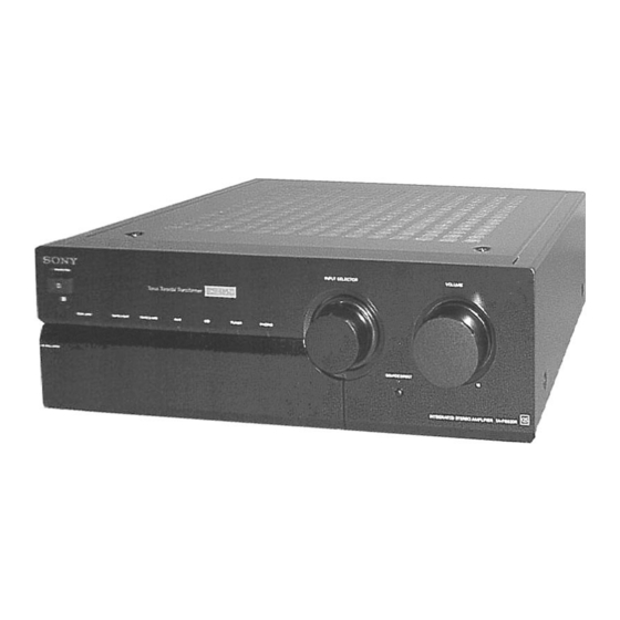
Page 1: Service Manual
TA-FB930R SERVICE MANUAL AEP Model Photo: BLACK model SPECIFICATIONS INTEGRATED STEREO AMPLIFIER MICROFILM... -
Page 2: Table Of Contents
COMPONENTS IDENTIFIED BY MARK ! OR DOTTED LINE WITH MARK ! ON THE SCHEMATIC DIAGRAMS AND IN THE PARTS LIST ARE CRITICAL TO SAFE OPERATION. REPLACE THESE COMPONENTS WITH SONY PARTS WHOSE PART NUMBERS APPEAR AS SHOWN IN THIS MANUAL OR IN SUPPLEMENTS PUBLISHED BY SONY. -
Page 3: General
SECTION 1 GENERAL Front Panel Descriptions 1 PROTECTION indicator 12 VOLUME knob 2 U (Power) button 13 SOURCE DIRECT button and indicator 3 Remote sensor 14 TAPE MONITOR knob 4 EON LINK indicator 15 SUBSONIC button 5 TAPE 1/DAT indicator 16 LOUDNESS button 17 BALANCE knob 6 TAPE 2/MD indicator... -
Page 4: Electrical Adjustment
SECTION 2 ELECTRICAL ADJUSTMENT Bias Adjustment NOTE: 1. Perform the adjustment after the unit has warmed up sufficiently. 2. Perform the bias adjustment if the power transistor has been replaced. Procedure: 1. Rotate fully the bias adjusting semi-fixed resistors (RV500, RV600) to the MIN position (counterclockwise). -
Page 5: Diagrams
SECTION 3 DIAGRAMS 3-1. CIRCUIT BOARDS LOCATION WAVEFORM THIS NOTE IS COMMON FOR PRINTED WIRING BOARDS AND SCHEMATIC DIAGRAMS. (In addition to this, the necessary note is printed in each block.) 3.8Vp-p For schematic diagrams. 4MHz Note: IC902 1 XOUT •... -
Page 6: Schematic Diagram - Input Section
TA-FB930R 3-2. SCHEMATIC DIAGRAM – INPUT SECTION – (Page 8) (Page 10) (Page 10) -
Page 7: Printed Wiring Board - Input Section
TA-FB930R 3-3. PRINTED WIRING BOARD – INPUT SECTION – • See page 5 for Circuit Boards Location. (Page 11) (Page 11) (Page 9) • Semiconductor Location Ref. No. Location D100 D101 A-10 D102 B-10 D103 B-10 D104 C-10 D105 D-10... -
Page 8: Schematic Diagram - Main Section
TA-FB930R 3-4. SCHEMATIC DIAGRAM – MAIN SECTION – • See page 14 for IC Block Diagrams. (Page 10) (Page 10) (Page (Page 12) (Page (Page 6) -
Page 9: Printed Wiring Board - Main Section
TA-FB930R 3-5. PRINTED WIRING BOARD – MAIN SECTION – • Semiconductor • Semiconductor • See page 5 for Circuit Boards Location. Location Location (Page 13) Ref. No. Location Ref. No. Location D511 D500 C-10 D501 C-10 D512 D513 D502 C-10... -
Page 10: Schematic Diagram - Panel Section
TA-FB930R 3-6. SCHEMATIC DIAGRAM – PANEL SECTION – • See page 5 for Waveform. • See page 14 for IC Block Diagrams. • See page 14 for IC Pin Function. (Page 6) (Page 10) (Page 8) (Page 8) (Page 6) -
Page 11: Printed Wiring Board - Panel Section
TA-FB930R 3-7. PRINTED WIRING BOARD – PANEL SECTION – • See page 5 for Circuit Boards Location. (Page 9) • Semiconductor Location Ref. No. Location D901 B-13 D902 D903 D904 D905 D906 B-10 D907 B-11 D910 B-11 D911 B-11 D912... -
Page 12: Schematic Diagram - Power Section
TA-FB930R 3-8. SCHEMATIC DIAGRAM – POWER SECTION – (Page 8) (Page 8) -
Page 13: Printed Wiring Board - Power Section
TA-FB930R 3-9. PRINTED WIRING BOARD – POWER SECTION – • See page 5 for Circuit Boards Location. (Page 9) (Page 9) -
Page 14: Ic Block Diagrams
3-10. IC BLOCK DIAGRAMS 3-11. IC PIN FUNCTION • IC902 Input Control & LED Drive (TMP47C103N-JP47) (Panel Board) • Main Board Pin No. Pin Name Function X OUT IC700 uPC1237HA System clock (4MHz) X IN RESET Reset input OVER LOAD DET Mode select input (Connected to ground) VOL + Motor drive output (+) -
Page 15: Exploded View
SECTION 4 EXPLODED VIEWS NOTE: The components identified by • The mechanical parts with no reference number in • -XX, -X mean standardized parts, so they may have mark ! or dotted line with mark the exploded views are not supplied. some difference from the original one. -
Page 16: Front Panel Section
3-024-055-01 BUTTON (POWER)(BLACK) * 56 4-999-492-01 CUSHION (DOOR)(BLACK) * 56 4-999-492-11 CUSHION (DOOR)(SILVER) 3-024-055-22 BUTTON (POWER)(SILVER) 4-942-568-41 EMBLEM (NO.5), SONY (BLACK) 4-999-406-01 KNOB(D18)(BLACK) 4-999-406-11 KNOB(D18)(SILVER) 4-942-568-61 EMBLEM (NO.5), SONY (SILVER) 4-980-773-01 BUTTON (DIA. 6)(BLACK) 4-218-232-02 EMBLEM (MOS) 4-980-773-12 BUTTON (DIA. 6)(SILVER) -
Page 17: Chassis Section
4-3. CHASSIS SECTION supplied Q511 Q611 Q612 Q702 Q512 supplied supplied supplied Supplied with RV301, supplied RV302,RV303,S801,S903 supplied not supplied supplied Supplied with J801 Supplied not supplied with S902 Supplied with RV300 The components identified by mark ! or dotted line with mark ! are critical for safety. -
Page 18: Electrical Parts List
SECTION 5 INPUT ELECTRICAL PARTS LIST Note: • SEMICONDUCTORS • Due to standardization, replacements in the parts list The components identified by In each case, u: µ , for example: may be different from the parts specified in the mark ! or dotted line with mark uA...: µ... - Page 19 INPUT MAIN Ref. No. Part No. Description Remark Ref. No. Part No. Description Remark < RELAY > < DIODE > RY100 1-515-614-11 RELAY D500 8-719-911-19 DIODE 1SS119-25 RY101 1-515-614-11 RELAY D501 8-719-911-19 DIODE 1SS119-25 RY102 1-515-614-11 RELAY D502 8-719-911-19 DIODE 1SS119-25 RY103 1-515-614-11 RELAY D503...
- Page 20 MAIN OUTLET PANEL Ref. No. Part No. Description Remark Ref. No. Part No. Description Remark Q613 8-729-140-84 TRANSISTOR 2SC1841-PAFAEA ! R622 1-208-603-11 REGISTER Q614 8-729-140-84 TRANSISTOR 2SC1841-PAFAEA ! R623 1-208-603-11 REGISTER R624 1-259-424-11 CARBON 1/6W Q702 8-729-209-15 TRANSISTOR 2SD2012 ! R626 1-217-997-11 FUSIBLE 1/2W F <...
- Page 21 PANEL PHONO Ref. No. Part No. Description Remark Ref. No. Part No. Description Remark < DIODE > R901 1-249-393-11 CARBON 1/4W F D901 8-719-313-50 DIODE SEL6810A-TH12 (EON LINK) R905 1-249-429-11 CARBON 1/4W D902 8-719-313-50 DIODE SEL6810A-TH12 (PHONO) R906 1-249-429-11 CARBON 1/4W D903 8-719-313-50 DIODE SEL6810A-TH12 (TUNER)
- Page 22 PHONO S-D LED Ref. No. Part No. Description Remark Ref. No. Part No. Description Remark C257 1-126-059-11 ELECT 10uF A-4419-859-A PS BOARD, COMPLETE ***************** < CONNECTOR > < CAPACITOR > CN151 1-691-768-11 PLUG (MICRO CONNECTOR) 6P C750 1-128-974-11 ELECT 10000uF <...
- Page 23 S-D LED SIRCS SIRCS SUB SP-TM TONE Ref. No. Part No. Description Remark Ref. No. Part No. Description Remark < RESISTOR > < DIODE > R927 1-249-406-11 CARBON 1/4W F D511 8-719-911-19 DIODE 1SS119-25 D512 8-719-911-19 DIODE 1SS119-25 D513 8-719-911-19 DIODE 1SS119-25 ************************************************************** D700 8-719-024-99 DIODE 11ES2-NTA2B...
- Page 24 TA-FB930R TONE Ref. No. Part No. Description Remark Ref. No. Part No. Description Remark C302 1-136-153-00 FILM 0.01uF < VARIABLE RESISTOR > C303 1-136-155-00 FILM 0.015uF C304 1-136-165-00 FILM 0.1uF RV301 1-225-642-11 RES, VAR, CARBON 250K/250K (BALANCE) RV302 1-225-643-11 RES, VAR, CARBON 250K/250K (TREBLE TONE)