Welch Allyn Connex Vital Signs Monitor 6000 Series Service Manual
Hide thumbs
Also See for Connex Vital Signs Monitor 6000 Series:
- Service manual (131 pages) ,
- Directions for use manual (143 pages) ,
- Service manual (185 pages)

Related Manuals for Welch Allyn Connex Vital Signs Monitor 6000 Series


Summary of Contents for Welch Allyn Connex Vital Signs Monitor 6000 Series
- Page 1 ® Welch Allyn Connex Vital Signs Monitor 6000 Series™ Service manual Software versions 2.0X – 2.3X...
- Page 2 © 2018 Welch Allyn. All rights are reserved. To support the intended use of the product described in this publication, the purchaser of the product is permitted to copy this publication, for internal distribution only, from the media provided by Welch Allyn. No other use, reproduction, or distribution of this publication, or any part of it, is permitted without written permission from Welch Allyn.
-
Page 3: Table Of Contents
Overview ....................9 Purpose and scope ....................9 Technical support services ................. 10 Recommended service intervals ................ 14 The Welch Allyn Service Tool ................15 Battery performance ..................16 Controls, indicators, and connectors ........... 19 Service menu ..................23 Access the Service screens ................23 General tab ...................... - Page 4 ® iv Contents Welch Allyn Connex Vital Signs Monitor 6000 Series™ Disassemble the front housing ................ 110 Section B ....................125 Power down the device ................... 125 Remove the battery ..................126 Remove the rear housing ................. 127 Remove the communications door ..............130 Disassemble the rear housing .................
- Page 5 Service manual Contents v Service record ....................286...
- Page 6 ® vi Contents Welch Allyn Connex Vital Signs Monitor 6000 Series™...
-
Page 7: Symbols
Follow the operating instructions/directions for use (DFU) — mandatory action. A copy of the DFU is available on this website. A printed copy of the DFU can be ordered from Welch Allyn for delivery within 7 days. Power symbols Power on/Display power-saving... - Page 8 ® Symbols Welch Allyn Connex Vital Signs Monitor 6000 Series™ (on the monitor, green indicator) Battery charge level Alternating Current power present, battery fully charged (on the monitor, amber indicator) Battery cover Alternating Current power present, battery is charging Alternating Current (AC)
- Page 9 Service manual Symbols 3 Nonionizing electromagnetic Recycle the product separate from radiation other disposables Restrictions for use of wireless Call for maintenance device in Europe. European Community's Class 2 radio equipment. Defibrillation-proof Type BF applied Defibrillation-proof Type CF applied parts parts Atmospheric pressure limitation Not for injection...
- Page 10 ® Symbols Welch Allyn Connex Vital Signs Monitor 6000 Series™...
-
Page 11: Safety
Safety All users of the monitor must read and understand all safety information presented in this manual before using or repairing the monitor. United States federal law restricts this device to sale, distribution, or use by or on the order of a licensed medical practitioner. Warnings and cautions WARNING Safety risk. -
Page 12: General Safety Considerations
Always follow the manufacturer’s directions for use. • Welch Allyn recommends that only Welch Allyn service personnel or an authorized repair center perform warranty service. Performing unauthorized service on a device that is within warranty may void the warranty. - Page 13 Service manual Safety 7 • Use only grounded tools when inserting, adjusting, or removing static-sensitive components and assemblies. • Remove or insert static-sensitive components and assemblies only with monitor power turned off. • Insert and seal static-sensitive components and assemblies into their original static- shielding bags before removing them from static-protected areas.
- Page 14 ® 8 Safety Welch Allyn Connex Vital Signs Monitor 6000 Series™...
-
Page 15: Overview
Purpose and scope This manual is a reference for periodic preventive maintenance and corrective service procedures for the Welch Allyn Connex Vital Signs Monitor 6000 Series, firmware versions 2.0X–2.3X. It is intended for use only by trained and qualified service personnel. -
Page 16: Technical Support Services
Partners in Care service agreements While product warranties provide basic assurance of Welch Allyn hardware quality, they may not include the full range of services and support you need. Welch Allyn offers premium service and support through our Partners in Care program. Whether you service your own devices and require a minimum of support or rely on us to service your device, Welch Allyn provides a program that will meet your needs. - Page 17 Qualified service personnel or a Welch Allyn Service Center should repair products out of warranty. If you are advised to return a product to Welch Allyn for repair or routine maintenance, schedule the repair with the service center nearest you.
- Page 18 Packaging requirements for Lithium-ion batteries and associated devices • Use packaging provided by Welch Allyn or the battery manufacturer to pack the battery. Seal the battery in the anti-static bag and place it in the shipping box. Return shipments without approved packing materials will not be...
- Page 19 Remember that batteries must be removed from devices before packing and shipping them for return. e. Write the Welch Allyn RMA number with the Welch Allyn address on the outside of the shipping carton. WARNING Safety risk. Do not ship any battery that has...
-
Page 20: Recommended Service Intervals
To confirm that the device is functioning within the design specifications, perform periodic service as indicated in the following table. Customers who have the Standard unlicensed edition of the Welch Allyn Service Tool can perform the basic functional verification and calibration procedures referenced in the table by following the instructions in this manual. -
Page 21: The Welch Allyn Service Tool
Welch Allyn technical training course or complete online training for the device. Clinicians and technical service personnel can use the service tool to manage and maintain supported Welch Allyn products. You can use the service tool to do the following: •... -
Page 22: Battery Performance
Vital Signs Monitor 6000 Series™ • Recover devices. In the rare case where a device can no longer boot because of corrupted firmware, the service tool can connect the device to Welch Allyn Technical Support to reinstall the firmware. •... - Page 23 Service manual Overview 17 ○ For storage more than 90 days up to 2 years: Maintain temperature between –4 °F and 95 °F (–20 °C and 35 °C). • Recycle batteries where ever possible. In the United States call 1-877-723-1297 for information about recycling your Lithium-ion battery or go to the Call2Recycle website at http://www.call2recycle.org...
- Page 24 ® 18 Overview Welch Allyn Connex Vital Signs Monitor 6000 Series™...
-
Page 25: Controls, Indicators, And Connectors
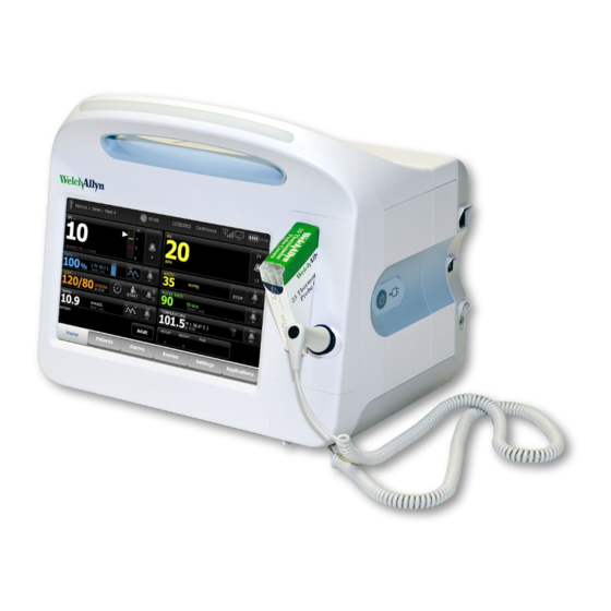
Controls, indicators, and connectors The following diagrams show a full-featured monitor. Your monitor, based on size or configuration, might not contain all of these features. Top-Left-Front view No. Feature Description Printer Printer provides a printout of patient and device information. Light bar Provides a visual alarm with red and amber LEDs. - Page 26 ® 20 Controls, indicators, and connectors Welch Allyn Connex Vital Signs Monitor 6000 Series™ No. Feature Description Blood pressure Supports dual-lumen or single-lumen hoses. Pulse oximetry Nellcor or Masimo rainbow SET module. The Nellcor module measures SpO2 and pulse rate.
- Page 27 Service manual Controls, indicators, and connectors 21 No. Feature Description Nurse call Provides a connection to the hospital nurse call system. (Not available on the 6300 model.) Fan exhaust Ground lug (equipotential terminal) Provided for electrical safety testing and as a means for connection of a potential-equalization conductor.
- Page 28 ® 22 Controls, indicators, and connectors Welch Allyn Connex Vital Signs Monitor 6000 Series™...
-
Page 29: Service Menu
Service menu Access the Service screens Note You cannot access the Service screens if sensors or physiological alarms are active or if vital sign measurements are displayed. 1. From the Home tab, touch the Settings tab. 2. Touch the Advanced tab. 3. - Page 30 ® 24 Service menu Welch Allyn Connex Vital Signs Monitor 6000 Series™ If you selected All settings, the device reboots. Save the device configuration or custom data to a drive You can save the device configuration or custom data (custom modifiers and custom scoring) to a USB flash drive.
- Page 31 Service manual Service menu 25 2. Go to the Service screens as described in “Access the Service screens.” 3. Touch the General tab. 4. Select Configure from USB. A confirmation dialog appears. 5. Select Device configuration and/or Custom data XML. A confirmation dialog appears to confirm overwriting the existing configuration.
-
Page 32: Self-Tests Tab
® 26 Service menu Welch Allyn Connex Vital Signs Monitor 6000 Series™ Send device information to PartnerConnect The device sends technical information, such as log files, to PartnerConnect periodically. You can also manually send this information at any time by following this procedure. -
Page 33: Device Tab
Service manual Service menu 27 5. Touch OK. Copies of both log files are saved to the drive. Device tab View device and module information 1. Go to the Service screens as described in “Access the Service screens.” 2. Touch the Device tab. Device and module information appears for you to view. - Page 34 ® 28 Service menu Welch Allyn Connex Vital Signs Monitor 6000 Series™...
-
Page 35: Power-Up Sequence
2. Insert a fully charged battery into the system. 3. Upon each power up, confirm the following: a. The light bar flashes amber. b. The Welch Allyn startup screen appears. c. A beep sounds, followed by one chime. Note If no chimes sound, replace the speaker as specified in “Remove the speaker.”... - Page 36 ® Power-up sequence Welch Allyn Connex Vital Signs Monitor 6000 Series™...
-
Page 37: Troubleshooting
AC power and call Welch Allyn Technical Support immediately. CAUTION Replace parts, components, or accessories only with parts supplied or approved by Welch Allyn. The use of any other parts can lead to inferior device performance and will void the product warranty. - Page 38 ® 32 Troubleshooting Welch Allyn Connex Vital Signs Monitor 6000 Series™ Symptom Possible cause Suggested action An internal connection is faulty Check the power-flex cable connection at J6 on the main board. Check the AC power harness connections from the IEC connector to the power supply.
- Page 39 Service manual Troubleshooting 33 Mechanical Symptom Possible cause Suggested action Cracks in housing Non-approved cleaning agents Replace plastic housing as necessary. Use only approved cleaning agents. Display Symptom Possible cause Suggested action The touchscreen does not respond Software error Reboot the device. Press and hold the power button until the device shuts down.
-
Page 40: User Interface
® 34 Troubleshooting Welch Allyn Connex Vital Signs Monitor 6000 Series™ Symptom Possible cause Suggested action J19 on the main board. Replace the cable if damaged. A cable is damaged Replace the cable. The display is dim The brightness setting is too low Increase the brightness setting. - Page 41 Service manual Troubleshooting 35 Symptom Possible cause Suggested action communicate with the device. See the service tool help files. Replace the power cable to the communications board. USB accessories do not The accessory is defective Replace with a known good communicate with the monitor accessory.
- Page 42 ® 36 Troubleshooting Welch Allyn Connex Vital Signs Monitor 6000 Series™ Symptom Possible cause Suggested action The communications board is not receiving power Check the voltage from J49 on the main board for +5.0, ±0.5V DC. Replace the main board if necessary.
- Page 43 Check the error logs for NIBP errors. See the service tool help files for details on specific errors and suggested actions. Check with Welch Allyn for software updates. If no NIBP error is logged, the main board might Replace the main board if be defective necessary.
- Page 44 Check the error logs for SpO2 errors. See the service tool help files for details on specific errors and suggested actions. Check with Welch Allyn for software updates. If no SpO2 error is logged, the main board might Replace the main board if be defective necessary.
- Page 45 Check the error logs for CO2 errors. See the service tool help files for details on specific errors and suggested actions. Check with Welch Allyn for software updates. If no CO2 error is logged, the main board might Replace the main board if be defective necessary.
- Page 46 Suggested action No LTA alarm associated with LTA license not installed Remove device from service, patient injury or death contact Welch Allyn Technical Support, and return to Welch V-Tach, V- Fib, Asystole detection disabled Allyn for service. invalid data No LTA or ECG tile shows Alarms off in advanced settings Turn on alarms.
- Page 47 ECG vertical tab. Enable Patient has a pacemaker. ECG module unable to detect pacer Contact Welch Allyn Technical Support. Replace the module if necessary. No alarming snapshot was auto- Automatic print on ECG alarm disabled...
- Page 48 ® 42 Troubleshooting Welch Allyn Connex Vital Signs Monitor 6000 Series™ Temperature Symptom Possible cause Suggested action The temperature frame on the The USB cable is defective Replace the USB cable. display is blank The temperature module is not connected Check the internal USB connection.
- Page 49 Service manual Troubleshooting 43 Braun ThermoScan PRO 6000 thermometer Symptom Possible cause Suggested action Braun measurements are inaccurate Probe lens is displaced Examine lens for displacement. If you observe a gap in the seam between the bezel and the lens, replace the thermometer.
- Page 50 C/F button or return to the dock while holding the C/F button. Retry upgrade. *Host device Braun 6000 settings override configuration settings from Welch Allyn Service Tool. Note For additional troubleshooting tips for the thermometer, see the manufacturer’s product documentation.
- Page 51 Service manual Troubleshooting 45 Symptom Possible cause Suggested action Height or weight was changed Adjusting the height or weight clears BMI. Weight scale not connected BMI is available only from a weight scale with height. Printer Symptom Possible cause Suggested action The printer does not print The reactive side of the thermal paper does not Reverse the printer paper.
-
Page 52: Technical Alarm Messages
ID. Errors Symptom Possible cause Suggested action #000000001 An internal software error Power down and restart. If the error persists, call Welch Allyn Technical Support for service. #000000002 An unclassified hardware error #000000003 Graphics RAM POST #000000004 System RAM POST... - Page 53 See the service tool help files for details on specific errors and suggested actions. Check with Welch Allyn for software updates. Filter line disconnected. The sampling line is not connected to the monitor Connect a sampling line to the monitor.
- Page 54 ® 48 Troubleshooting Welch Allyn Connex Vital Signs Monitor 6000 Series™ Message Possible cause Suggested action module to reset before calibrating CO2. Move to a location where the ambient temperature enables the module temperature to return to normal and the module to reset before calibrating CO2.
- Page 55 Service manual Troubleshooting 49 Patient movement messages Message Possible cause Suggested action Replace the bed sensor. The sensor is faulty or expired. Replace the bed sensor. The cable is faulty or expired. Replace the cable. The bed sensor is disconnected. The bed sensor is disconnected from the monitor.
- Page 56 ® 50 Troubleshooting Welch Allyn Connex Vital Signs Monitor 6000 Series™ Message Possible cause Suggested action An unqualified mattress type is in use Switch to a qualified mattress type. EarlySense is not functional. A module error occurred. Call for service.
- Page 57 Check the error logs for NIBP service. errors. See the service tool help files for details on specific errors and suggested actions. Check with Welch Allyn for software updates. The ambient temperature is out of range Use the monitor in the specified temperature range.
- Page 58 Check the error logs for SpO2 errors. See the service tool help files for details on specific errors and suggested actions. Check with Welch Allyn for software updates. Attach SpO2 sensor to monitor. The sensor was not detected Check the sensor connection.
- Page 59 Service manual Troubleshooting 53 Message Possible cause Suggested action message persists after you have installed the SpO2 tester, replace the module. Searching for SpO2. (High-priority The SpO2 sensor is not attached to the patient’s Touch the alarm icon or the SpO2 alarm) finger frame to dismiss the alarm.
- Page 60 ® 54 Troubleshooting Welch Allyn Connex Vital Signs Monitor 6000 Series™ Message Possible cause Suggested action The temperature module returned a connect Connect a temperature probe and probe message try again. If a probe is already connected, replace the probe.
- Page 61 Service manual Troubleshooting 55 Temperature messages (Braun ThermoScan PRO) Message Possible cause Suggested action Alarm Unable to detect temperature. Retry measurement. Measurement was not taken Retry measurement. Measurement recalled from memory Loose or broken USB cable Check USB connection and cable. Replace as necessary.
- Page 62 See the service tool help files for details on specific errors and suggested actions. Check with Welch Allyn for software updates. The USB cable is disconnected Check the USB cable. The battery is depleted or missing Replace the batteries.
- Page 63 Service manual Troubleshooting 57 Message Possible cause Suggested action the ECG module if necessary. ECG module has not transmitted ECG Check the USB cable and data for the past 30 seconds connections. Perform functional test. If the test fails, contact Customer Care and replace the ECG module if necessary.
- Page 64 ® 58 Troubleshooting Welch Allyn Connex Vital Signs Monitor 6000 Series™ Message Possible cause Suggested action Check the patient cable connection to the ECG module. Perform functional test. If the test fails, contact Customer Care and replace the ECG module if necessary.
- Page 65 Service manual Troubleshooting 59 Message Possible cause Suggested action Printer door is open; close to The printer door is open Close the printer door. continue Out of paper. The paper is not properly loaded Align the paper with the print head.
- Page 66 ® 60 Troubleshooting Welch Allyn Connex Vital Signs Monitor 6000 Series™ Communications module messages Message Possible cause Suggested action Communications module did not The communications board is not connected Check the USB connection at J4. power on properly. Power down...
- Page 67 Check the external device. Check external and internal USB connections. Information External device not licensed for A device requiring a license has been connected Obtain an authorization code use. to the USB connection from Welch Allyn to activate the license.
-
Page 68: System Messages
Vital Signs Monitor 6000 Series™ Message Possible cause Suggested action Unable to save configuration to There was a problem writing the configuration Use a Welch Allyn approved USB. file to the USB flash drive flash drive. Verify that the flash drive is not locked. - Page 69 Service manual Troubleshooting 63 Battery power manager messages Message Possible cause Suggested action Alarm Low battery 5 minutes or less Battery power is extremely low Plug the monitor into AC power. remaining. (High-priority alarm) If not plugged in, the monitor automatically powers off.
- Page 70 ® 64 Troubleshooting Welch Allyn Connex Vital Signs Monitor 6000 Series™ Message Possible cause Suggested action Maximum number of patient The maximum number of patient records has Go to the Review tab and delete records saved. Oldest record been saved on the device old records to prevent the alarm overwritten.
-
Page 71: Disassembly And Repair
Disassembly and repair This chapter is divided into two major subsections, defined in the table below. Section A Section B (IEC 60601 3rd-edition compliant) Devices meeting these criteria: Devices meeting these criteria: • Manufactured before 12/2017* • Manufactured after 12/2017* •... - Page 72 For more information about these tests and the service tool, see “Functional verification and calibration.” If you do not have the service tool, contact Welch Allyn Technical Support. EarlySense and CO2 can be installed only on the extended chassis. Note...
-
Page 73: Required Tools And Equipment
Service manual Disassembly and repair 67 Required tools and equipment • #1 Phillips bit • #2 Phillips bit • #10 Torx bit • 5/16-inch socket • Torque driver calibrated for 6.0 in-lb ±1.0 in-lb • Torque driver calibrated for 7.5 in-lb ±0.5 in-lb •... -
Page 74: Disassembly Overview
® 68 Disassembly and repair Welch Allyn Connex Vital Signs Monitor 6000 Series™ Disassembly overview The following chart provides an overview of the complete disassembly of the device. Most disassembly activities require that you complete a subset of the steps detailed here. -
Page 75: Section A
Section A This section applies to devices manufactured before 12/2017, serial numbers before 100043244817, and MCE hardware version P3 or earlier. Note If your device does not meet these criteria, see Section B for the correct disassembly and repair instructions. If the MCE hardware version is P2 or P3, DO NOT replace any components with service kits with the "3rd Ed"... -
Page 76: Remove The Rear Housing
® 70 Section A Welch Allyn Connex Vital Signs Monitor 6000 Series™ 2. Locate the battery cover, indicated by 3. Insert a coin into the slot and push to open. Choose a coin that fits comfortably into the slot. 4. Pull the battery out by pulling the battery label, which is visible when you open the battery cover. - Page 77 Service manual Section A 71 Item Item Rear housing Communications door USB label 4 USB host Communications door captive screw USB label 1 USB host (model 6300 only) IEC connector Nurse call label Screw, M4 X 10 pan head with NYLOC No nurse call label (model 6300 only) Before you begin, power down the device, disconnect the AC power cord, and remove the battery as described in this manual.
- Page 78 ® 72 Section A Welch Allyn Connex Vital Signs Monitor 6000 Series™ c. Disconnect the fan cable (A) from the main harness. d. Separate the rear housing (1) from the monitor. Once the rear housing is removed, choose which part of the monitor to work on: •...
-
Page 79: Remove The Communications Door
Service manual Section A 73 c. Insert the USB cable into the client USB connection, press and remove the cable to adhere the cover to the rear housing. 6. Install these labels: • USB label (2a for models 6400, 6500, 6700, and 6800; 2b for model 6300) in the communications door opening. - Page 80 ® 74 Section A Welch Allyn Connex Vital Signs Monitor 6000 Series™ 4. Carefully remove the door from the rear housing. When replacing the communications door WARNING Personal injury risk. Because attaching the door might propel the pin and spring into the air, wear safety glasses to complete these steps.
- Page 81 Service manual Section A 75 3. Press the pin into the left side of the door and slide the door into the hinge of the rear housing until it snaps into place.
-
Page 82: Disassemble The Rear Housing
® 76 Section A Welch Allyn Connex Vital Signs Monitor 6000 Series™ Disassemble the rear housing Item Item Rear housing Communications board (Model 6300) IEC connector Communications board (Models 6400, 6500, 6700, and 6800) Screw, plastite #4-20 X 0.500 Torx-pan head Radio board, 802.11a/b/g... - Page 83 Service manual Section A 77 Remove the communications board Before you begin, remove the following as described in this manual: • Battery • Rear housing 1. Lay the rear housing on its back on the antistatic mat. 2. Remove the four Torx screws (10) that secure the communications board (20a or 20b) to the rear housing.
- Page 84 ® 78 Section A Welch Allyn Connex Vital Signs Monitor 6000 Series™ Remove the radio board and antenna CAUTION Do not remove the radio antenna from the rear housing unless replacing the radio and antenna or the rear housing. Before you begin, remove the following as described in this manual: •...
- Page 85 Service manual Section A 79 4. Remove the power-supply cover (18). 5. Use a soft tool such as a spudger to separate the foam block (24) from the inside of the rear housing. Reassembly notes Route the antenna cable in the channel located at the top of the rear housing. When replacing the radio board and antenna 1.
- Page 86 ® 80 Section A Welch Allyn Connex Vital Signs Monitor 6000 Series™ 4. Expose the adhesive on the foam block. Mount the antenna (16) on the foam block with the antenna cable (39) oriented under the board and in the wire channel above the power supply.
- Page 87 Service manual Section A 81 Reassembly notes CAUTION Ensure that the fan is properly oriented. Air must flow toward the power supply. Note If the fan is dirty, use canned air to remove dust. Do not bend the fan blades or otherwise damage the fan. If the fan is noisy and cleaning does not reduce the noise, replace the fan.
- Page 88 ® 82 Section A Welch Allyn Connex Vital Signs Monitor 6000 Series™ 4. Remove the power supply. Remove the AC power harness Note Do not disconnect the AC power harness from the IEC connector unless you are replacing it. Once you disconnect the AC power harness, you cannot reuse it.
- Page 89 Service manual Section A 83 • Plug the ground cable from the IEC connector onto the ground plate in the position closest to the IEC connector. • Ensure that the green ground wires are routed over the blue and brown wires. •...
-
Page 90: Disassemble The Main Chassis
® 84 Section A Welch Allyn Connex Vital Signs Monitor 6000 Series™ Disassemble the main chassis Disassembly and reassembly procedures are the same for the standard chassis and extended chassis, unless otherwise noted. Configuration options Standard chassis (left side) Extended chassis (left side) - Page 91 Service manual Section A 85 Extended chassis (right side) Supports a maximum of one module Note The standard chassis is the same as extended chassis minus space for an EarlySense module, so it is not presented here. Components (front to back): Power button, EarlySense, Ethernet RJ-45, USB client, Nurse call Power button, Blank, Ethernet RJ-45, USB client, Nurse call Note...
- Page 92 ® 86 Section A Welch Allyn Connex Vital Signs Monitor 6000 Series™ Main chassis exploded view More detailed views of main chassis components and tables identifying specific parts appear later in this section preceding the associated disassembly and repair instructions.
- Page 93 Service manual Section A 87 Item Item Speaker Temperature mounting cover Bottom housing HSG clamp Battery connector board LCD frame Battery door Grommet, ear - G411-1 Handle insert Shoulder screw, ear G-411-1 metric Top housing Clamp, cable 3/16 X 3/8 wide X 3/4 long Light bar Washer, M3 Light-bar board...
- Page 94 ® 88 Section A Welch Allyn Connex Vital Signs Monitor 6000 Series™ Remove the CO2 module Before you begin, remove the following as described in this manual: • Battery • Rear housing 1. Disconnect the two USB cables from the CO2 module.
- Page 95 Service manual Section A 89 2. Using a slotted screwdriver, release the three plastic clips from the module rear housing, and remove the clear housing cover. 3. Disconnect the exhaust tube from the exhaust port on the faceplate. 4. Remove the spring clip from the input port, and slide the input port away from the faceplate.
- Page 96 ® 90 Section A Welch Allyn Connex Vital Signs Monitor 6000 Series™ 6. Inspect the new faceplate before installing it: a. Verify that the spring is attached to the door latch. b. Verify that the door opens and closes freely.
- Page 97 Service manual Section A 91 The exhaust tube runs along the back of the module and Note gradually bends to the exhaust fitting. The inlet tube and wire run around the molded feature and boss to the large connector. 11. Install the clear housing cover onto the module rear housing, and press the cover into place until the three plastic clips lock.
- Page 98 ® 92 Section A Welch Allyn Connex Vital Signs Monitor 6000 Series™ 2. Slide the EarlySense module out of the case. Reassembly notes Insert the EarlySense module into the housing with the serial number label facing down. When replacing the EarlySense module or adding an EarlySense module •...
- Page 99 Service manual Section A 93 Reassembly notes • Install the NIBP module (the module closest to the display) before installing the SpO2 module. • Insert the SpO2 module into the housing with the serial number label facing up. When replacing the SpO2 module or adding an SpO2 module CAUTION Ensure that your module has the correct option (Masimo or Nellcor).
- Page 100 ® 94 Section A Welch Allyn Connex Vital Signs Monitor 6000 Series™ 2. Slide the NIBP module out of the case. Reassembly notes • Install the NIBP module (the module closest to the display) before installing the SpO2 and CO2 modules.
- Page 101 Service manual Section A 95 Item Item Speaker Battery door Extended bottom housing for the extended chassis Item Item Screw, plastite #4-20 X 0.500 Torx-pan head Battery door Bottom housing metal chassis Extended bottom housing Speaker M4 standoff Battery connector board Before you begin, remove the following as described in this manual: •...
- Page 102 ® 96 Section A Welch Allyn Connex Vital Signs Monitor 6000 Series™ 2. If your model has an extended chassis, remove the insert shown below. 3. If your model has a printer, do the following: a. Remove the drain tube located between the printer and the bottom plate.
- Page 103 Service manual Section A 97 5. Pull the speaker wire out from behind the bottom bracket and disconnect the speaker cable (26) from the main harness. 6. Disconnect the following on the battery connector board: a. The battery power harness from J2. b.
- Page 104 When replacing the bottom housing Note The bottom housing, or extended bottom housing, must be replaced by a Welch Allyn service center to ensure proper labeling. Remove the speaker Before you begin, remove the following as described in this manual: •...
- Page 105 Service manual Section A 99 • Bottom housing 1. Remove the metal chassis to more easily access the speaker. 2. Remove the speaker (26) from the bottom housing. 3. Remove any remaining gasket material and clean the surface with 70 percent isopropyl alcohol.
- Page 106 ® 100 Section A Welch Allyn Connex Vital Signs Monitor 6000 Series™ Remove the top housing Top housing Item Item Screw, M4 X 10 pan head with NYLOC Paper feed roller Handle insert Printer housing Top housing Screw, M2.2X8, Thrdform, PNH, TRX...
- Page 107 Service manual Section A 101 Housing top extension (extended chassis only) Item Item M4 standoff Top housing gasket Housing top extension Before you begin, remove the following as described in this manual: • Battery • Rear housing • CO2 module or blank faceplate •...
- Page 108 ® 102 Section A Welch Allyn Connex Vital Signs Monitor 6000 Series™ 4. For models that include the temperature option, disconnect the USB cable connected to the temperature module from J1 on the main board and free the USB cable from the cable separator.
- Page 109 Service manual Section A 103 a. The fan cable on the main harness from J45 on the main board. b. The communications power cable on the main harness from J49 on the main board. c. The battery power harness from J29 on the main board. d.
- Page 110 ® 104 Section A Welch Allyn Connex Vital Signs Monitor 6000 Series™ ○ The smart-battery harness to J34 on the main board. ○ The printer harness to J17 on the main board. ○ The speaker cable on the main harness to J12 on the main board.
- Page 111 Service manual Section A 105 Item Item Temperature NIBP Printer COMMS J4 SpO2 COMMS J8 USB cable locations—11-hole cable separator • Place the USB cables in the cable separator. Note If the USB cable was not removed from the temperature module, leave the J1 position in the figure below vacant until the cable separator is placed in the case and the other USB cables have been connected to the main board.
- Page 112 ® 106 Section A Welch Allyn Connex Vital Signs Monitor 6000 Series™ • Plug the USB cables into the main board as follows: • Place the USB cables in the cable separator. Note If the USB cable was not removed from the temperature...
- Page 113 Service manual Section A 107 Item Item Temperature SpO2 Printer NIBP EarlySense COMMS J4 COMMS J8 • For models with a temperature module, if you disconnected the USB cable from the temperature module during disassembly, you must replace the retaining clip. (See the topic "When replacing the temperature module"...
- Page 114 ® 108 Section A Welch Allyn Connex Vital Signs Monitor 6000 Series™ • When installing the housing top extension (75), verify that the top housing gasket is in place. Use a 5/16-inch socket and Torque driver calibrated for 12.0 inch-pound ±1.0 inch-pound to secure the standoffs (74).
- Page 115 Service manual Section A 109 Reassembly notes 1. Verify that the ground wire exits from the side opposite the printer board in the notched area. 2. Place the printer door into the top housing assembly and hold it in place while performing the next step.
-
Page 116: Disassemble The Front Housing
® 110 Section A Welch Allyn Connex Vital Signs Monitor 6000 Series™ Disassemble the front housing Item Item Screw, plastite #4-20 X 0.500 Torx-pan head Foam pad Light bar Temperature module Light-bar board Temperature housing Right side panel Probe well seal... - Page 117 Service manual Section A 111 Item Item LCD bezel (2nd generation displays) Washer, M3 LCD with touchscreen (1st generation displays) Left insert LCD with touchscreen (2nd generation displays) Temperature connection access cover Foam pad Remove the light bar Before you begin, remove the following as described in this manual: •...
- Page 118 ® 112 Section A Welch Allyn Connex Vital Signs Monitor 6000 Series™ 4. Disconnect the light-bar harness from J46 on the main board. 5. Remove the light-bar board (34) and light bar (33) from the front housing. 6. Remove the light-bar board from the light bar.
- Page 119 Service manual Section A 113 • NIBP module • Bottom housing • Top housing Note You can remove and replace the temperature module without disconnecting the main harness, battery harnesses, USB cables, or light-bar harness from the main board. 1. Remove the probe well from the temperature module. 2.
- Page 120 ® 114 Section A Welch Allyn Connex Vital Signs Monitor 6000 Series™ a. Remove the screw that secures the temperature mounting cover to the front housing. b. Remove the temperature mounting cover (56) from the front housing. • If your monitor does not have a temperature module, remove the temperature blanking panel: a.
- Page 121 Service manual Section A 115 5. Secure the USB cable with a piece of tape as shown. When adding a temperature module 1. Follow the instructions to remove the temperature housing, main board, and LCD. 2. Replace the temperature blanking panel (44) with the temperature mounting cover (56).
- Page 122 ® 116 Section A Welch Allyn Connex Vital Signs Monitor 6000 Series™ 9. Place the HSG clamp on the bottom of the temperature module and secure with two screws. 10. Connect the USB cable to the module as described in the instructions for replacing the temperature module.
- Page 123 Service manual Section A 117 Item Item LCD bezel Shoulder screw, ear G-411-1 metric LCD with touchscreen Clamp, cable 3/16 X 3/8 wide X 3/4 long Foam pad, bottom (1st generation displays) Washer, M3 Configuration B - 2nd generation displays Item Item Front housing...
- Page 124 ® 118 Section A Welch Allyn Connex Vital Signs Monitor 6000 Series™ • NIBP module • Bottom housing • Top housing Note It is not necessary to remove the temperature module or light bar to remove the main board or LCD.
- Page 125 Service manual Section A 119 4. Remove the main board. Reassembly notes • Ensure that the LCD flex cable is not under the main board. CAUTION The solder joint of the LCD connector (J48) is fragile. When inserting or removing the flex cable, do not stress the solder joint.
- Page 126 Update the host controller software to the current version. If the current version of the host software is not available after connecting the device to the service tool, contact Welch Allyn Technical Support. Remove the LCD Before you begin, remove the following as described in this manual: •...
- Page 127 Service manual Section A 121 It is not necessary to remove the temperature module or light bar to Note remove the main board or LCD. 1. Disconnect the LCD harness from the LCD. For easier access to the connector, you can slide the ferrite bead closest to the connector up the harness.
- Page 128 ® 122 Section A Welch Allyn Connex Vital Signs Monitor 6000 Series™ When replacing the LCD frame • Install a 3-inch strip of Pro Gaff tape on the back of the LCD frame to cover the bottom of the standoffs. This tape will prevent any small pieces of metal left over from the threading process from falling into the display where it might cause a short.
- Page 129 Service manual Section A 123 1st generation displays 2nd generation displays • Verify that the LCD flex cable feeds through the bezel's clearance feature. • Add a 1.25-inch strip of tape to the edge of the LCD frame where the LCD flex cable and ground come around it.
- Page 130 ® 124 Section A Welch Allyn Connex Vital Signs Monitor 6000 Series™...
-
Page 131: Section B
Section B This section applies to devices that meet all of the following criteria: • manufactured after 12/2017 • MCE hardware version P5 or later • serial number after 100043244817. These devices comply with IEC 60601 3rd edition. If your device does not meet these criteria, see Section A for the correct Note disassembly and repair instructions. -
Page 132: Remove The Battery
® 126 Section B Welch Allyn Connex Vital Signs Monitor 6000 Series™ Option 2. To use onscreen controls alone to power down the device, follow these steps: 1. Touch the Settings tab. 2. Touch the Device tab. 3. Touch Power down. -
Page 133: Remove The Rear Housing
Service manual Section B 127 Remove the rear housing Item Item Rear housing Communications door captive screw USB label 4 USB host IEC connector Nurse call label Screw, M4 X 10 pan head with NYLOC Communications door Before you begin, power down the device, disconnect the AC power cord, and remove the battery as described in this manual. - Page 134 ® 128 Section B Welch Allyn Connex Vital Signs Monitor 6000 Series™ a. The Ethernet cable from J9. b. The small USB connector from J4. c. The large USB connector from J8. d. The communications power cable from J50. 8. Continuing to support the rear housing, do the following at the power-supply cover: a.
- Page 135 Service manual Section B 129 e. Separate the rear housing (1) from the monitor. Once the rear housing is removed, choose which part of the monitor to work on: • Rear housing components. For details, see “Disassemble the rear housing.” •...
-
Page 136: Remove The Communications Door
® 130 Section B Welch Allyn Connex Vital Signs Monitor 6000 Series™ c. Insert the USB cable into the client USB connection, press and remove the cable to adhere the cover to the rear housing. 6. Install these labels: •... - Page 137 Service manual Section B 131 4. Carefully remove the door from the rear housing. When replacing the communications door WARNING Personal injury risk. Because attaching the door might propel the pin and spring into the air, wear safety glasses to complete these steps.
- Page 138 ® 132 Section B Welch Allyn Connex Vital Signs Monitor 6000 Series™ 3. Press the pin into the left side of the door and slide the door into the hinge of the rear housing until it snaps into place.
-
Page 139: Disassemble The Rear Housing
Service manual Section B 133 Disassemble the rear housing Item Item Rear housing Communications board (Models 6400, 6500, 6700, and 6800) IEC connector Radio board, 802.11a/b/g Screw, plastite #4-20 X 0.500 Torx-pan head Screw, M3 X 0.5, Phillips pan head Rear housing gasket (Norprene tubing) Power supply board Antenna board... - Page 140 ® 134 Section B Welch Allyn Connex Vital Signs Monitor 6000 Series™ Remove the communications board Before you begin, remove the following as described in this manual: • Battery • Rear housing 1. Lay the rear housing on its back on the antistatic mat.
- Page 141 Service manual Section B 135 Remove the radio board and antenna CAUTION Do not remove the radio antenna from the rear housing unless replacing the radio and antenna or the rear housing. Before you begin, remove the following as described in this manual: •...
- Page 142 ® 136 Section B Welch Allyn Connex Vital Signs Monitor 6000 Series™ 4. Remove the power-supply cover (18). 5. Use a soft tool such as a spudger to separate the foam block (24) from the inside of the rear housing.
- Page 143 Service manual Section B 137 4. Expose the adhesive on the foam block. Mount the antenna (16) on the foam block with the antenna cable (39) oriented under the board and in the wire channel above the power supply. 5. Route the antenna cable in the channel located at the top of the rear housing. Remove the fan Before you begin, remove the following as described in this manual: •...
- Page 144 ® 138 Section B Welch Allyn Connex Vital Signs Monitor 6000 Series™ Reassembly notes CAUTION Ensure that the fan is properly oriented. Air must flow toward the power supply. Note If the fan is dirty, use canned air to remove dust. Do not bend the fan blades or otherwise damage the fan.
- Page 145 Service manual Section B 139 4. Remove the power supply. Remove the AC power harness Note Do not disconnect the AC power harness from the IEC connector unless you are replacing it. Once you disconnect the AC power harness, you cannot reuse it.
- Page 146 ® 140 Section B Welch Allyn Connex Vital Signs Monitor 6000 Series™ 4. Remove the ground stud AC power harness assembly. Reassembly notes When replacing the rear case or AC power harness, route the wiring as follows: • Connect blue to neutral (N), green to ground (GND), and brown to line (L).
- Page 147 Service manual Section B 141 ○ Ensure that the wires on the power supply wire harness ferrite are on the sides of the ferrite. ○ Confirm that the wires to the power supply and the LCD ground wire pass over the top of the wires to the ferrite.
-
Page 148: Disassemble The Main Chassis
® 142 Section B Welch Allyn Connex Vital Signs Monitor 6000 Series™ Disassemble the main chassis Disassembly and reassembly procedures are the same for the standard chassis and extended chassis, unless otherwise noted. Configuration options Standard chassis (left side) Extended chassis (left side) - Page 149 Service manual Section B 143 Extended chassis (right side) Supports a maximum of one module Note The standard chassis is the same as extended chassis minus space for an EarlySense module, so it is not presented here. Components (front to back): Power button, EarlySense, Ethernet RJ-45, USB client, Nurse call Power button, Blank, Ethernet RJ-45, USB client, Nurse call Note...
- Page 150 ® 144 Section B Welch Allyn Connex Vital Signs Monitor 6000 Series™ Main chassis exploded view More detailed views of main chassis components and tables identifying specific parts appear later in this section preceding the associated disassembly and repair instructions.
- Page 151 Service manual Section B 145 Item Item Bottom housing LCD frame Battery connector board Grommet, ear - G411-1 Battery door Shoulder screw, ear G-411-1 metric Handle insert Left insert Top housing Paper-feed roller Light bar Printer Light-bar board Temperature connection access cover Printer door Screw, M2.2X8, THRDFORM, PNH, TRX Right side panel...
- Page 152 ® 146 Section B Welch Allyn Connex Vital Signs Monitor 6000 Series™ 1. Disconnect the two USB cables from the CO2 module. 2. Slide the CO2 module out of the case. Reassembly notes • Do the following before installing the CO2 module: ○...
- Page 153 Service manual Section B 147 3. Disconnect the exhaust tube from the exhaust port on the faceplate. 4. Remove the spring clip from the input port, and slide the input port away from the faceplate. 5. Remove the faceplate: a. Disengage one plastic clip on the module rear housing from the faceplate. b.
- Page 154 ® 148 Section B Welch Allyn Connex Vital Signs Monitor 6000 Series™ 6. Inspect the new faceplate before installing it: a. Verify that the spring is attached to the door latch. b. Verify that the door opens and closes freely.
- Page 155 Service manual Section B 149 The exhaust tube runs along the back of the module and Note gradually bends to the exhaust fitting. The inlet tube and wire run around the molded feature and boss to the large connector. 11. Install the clear housing cover onto the module rear housing, and press the cover into place until the three plastic clips lock.
- Page 156 ® 150 Section B Welch Allyn Connex Vital Signs Monitor 6000 Series™ 2. Slide the EarlySense module out of the case. Reassembly notes Insert the EarlySense module into the housing with the serial number label facing down. When replacing the EarlySense module or adding an EarlySense module Use 106838 SK CVSM Early Sense Module 3rd Ed.
- Page 157 Service manual Section B 151 Reassembly notes • Install the NIBP module (the module closest to the display) before installing the SpO2 module. • Insert the SpO2 module into the housing with the serial number label facing up. When replacing the SpO2 module or adding an SpO2 module CAUTION Ensure that your module has the correct option (Masimo or Nellcor).
- Page 158 ® 152 Section B Welch Allyn Connex Vital Signs Monitor 6000 Series™ 2. Slide the NIBP module out of the case. Reassembly notes • Install the NIBP module (the module closest to the display) before installing the SpO2 and CO2 modules.
- Page 159 Service manual Section B 153 Item Item Bottom housing Lock washer Battery connector board Extended bottom housing for the extended chassis Item Item Screw, plastite #4-20 X 0.500 Torx-pan head Extended bottom housing Bottom housing metal chassis M4 standoff Speaker LCD frame ground wire Battery connector board Lock washer...
- Page 160 ® 154 Section B Welch Allyn Connex Vital Signs Monitor 6000 Series™ 2. If your model has an extended chassis, remove the insert shown below. 3. If your model has a printer, do the following: a. Remove the drain tube located between the printer and the bottom plate.
- Page 161 Service manual Section B 155 4. Cut the tie wrap that secures the main harness to the bottom bracket. This tie wrap is located below the tie wrap on the main harness. 5. Pull the speaker wire out from behind the bottom bracket and disconnect the speaker cable (26) from the main harness.
- Page 162 ® 156 Section B Welch Allyn Connex Vital Signs Monitor 6000 Series™ 8. Remove the following screws: • The bottom housing screw. • The two screws that secure the bottom housing assembly to the front housing. 9. Remove the bottom housing.
- Page 163 Service manual Section B 157 10. Disassemble the bottom housing: Note Disassemble the bottom housing only if you plan to replace the battery connector board or the speaker. See the instructions for removing these components later in this section. Reassembly notes •...
- Page 164 ® 158 Section B Welch Allyn Connex Vital Signs Monitor 6000 Series™ • Route the main harness wires over the USB cables and cable separator. • Replace the Pro Gaff tape securing the LCD ground wire to the battery frame. Tape the ground wire to the battery frame between the center rib and the holes on the right end.
- Page 165 When replacing the bottom housing Note The bottom housing, or extended bottom housing, must be replaced by a Welch Allyn service center to ensure proper labeling. Remove the speaker Before you begin, remove the following as described in this manual: •...
- Page 166 ® 160 Section B Welch Allyn Connex Vital Signs Monitor 6000 Series™ 3. Remove any remaining gasket material and clean the surface with 70 percent isopropyl alcohol. When replacing the speaker 1. Remove the paper to expose the adhesive on the gasket.
- Page 167 Service manual Section B 161 Remove the top housing Top housing Item Item Screw, M4 X 10 pan head with NYLOC Paper feed roller Handle insert Printer housing Top housing Screw, M2.2X8, Thrdform, PNH, TRX Printer door Not shown Printer door blank...
- Page 168 ® 162 Section B Welch Allyn Connex Vital Signs Monitor 6000 Series™ Housing top extension (extended chassis only) Item Item M4 standoff Top housing gasket Housing top extension Before you begin, remove the following as described in this manual: •...
- Page 169 Service manual Section B 163 3. Lay the main harness over the top of the unit to clear the USB cables. 4. Disconnect the power connector on the main harness from J30 on the main board. 5. For models that include the temperature option, disconnect the USB cable connected to the temperature module from J1 on the main board and free the USB cable from the cable separator.
- Page 170 ® 164 Section B Welch Allyn Connex Vital Signs Monitor 6000 Series™ 9. Disconnect and then remove the following: a. The fan cable on the main harness from J45 on the main board. b. The communications power cable on the main harness from J49 on the main board.
- Page 171 Service manual Section B 165 13. Remove the top housing. Reassembly notes • Ensure that the printer is installed in the top housing. See the reassembly notes for the printer. • For devices equipped with a printer, position the top housing close to the main chassis, connect the printer harness, and secure both the light bar harness and the printer harness to the LCD frame with approximately 2 inches of Pro Gaff tape.
- Page 172 ® 166 Section B Welch Allyn Connex Vital Signs Monitor 6000 Series™ • Position each cable to extend approximately 2 inches past the separator. • When positioning the separator in the device, place the feet in the marked areas of the MCE board as shown.
- Page 173 Service manual Section B 167 • Verify that the Ethernet cable passes freely through the space between the temperature housing and the printer board, exiting the case in the space between the top of the temperature housing and beneath the top housing. •...
- Page 174 ® 168 Section B Welch Allyn Connex Vital Signs Monitor 6000 Series™ 1. Remove the two Torx screws that secure the printer housing to the top housing. 2. Remove the printer from the top housing: a. Hold the printer housing while opening the printer door.
-
Page 175: Disassemble The Front Housing
Service manual Section B 169 Disassemble the front housing Item Item Screw, plastite #4-20 X 0.500 Torx-pan head Temperature module Light bar Temperature housing Light-bar board Probe well seal Right side panel Horizontal struts Power button Temperature mounting cover Front housing HSG clamp Temperature blanking panel LCD frame... - Page 176 ® 170 Section B Welch Allyn Connex Vital Signs Monitor 6000 Series™ Item Item LCD with touchscreen LCD frame ground wire Foam pad, top and bottom Lock washer Remove the light bar Before you begin, remove the following as described in this manual: •...
- Page 177 Service manual Section B 171 4. Disconnect the light-bar harness from J46 on the main board. 5. Remove the light-bar board (34) and light bar (33) from the front housing. 6. Remove the light-bar board from the light bar. 7. Disconnect the light-bar harness from the light-bar board. Reassembly notes •...
- Page 178 ® 172 Section B Welch Allyn Connex Vital Signs Monitor 6000 Series™ • NIBP module • Bottom housing • Top housing Note You can remove and replace the temperature module without disconnecting the main harness, battery harnesses, USB cables, or light-bar harness from the main board.
- Page 179 Service manual Section B 173 5. Remove the two Torx screws (10) that secure the top of the temperature module or empty housing. 6. Remove the temperature module or empty housing. Note If you are replacing only the temperature module without replacing the temperature mounting cover, stop here.
- Page 180 ® 174 Section B Welch Allyn Connex Vital Signs Monitor 6000 Series™ • Route the power button flex cable up and over the temperature module and plug the cable into the J6 ZIF locking connector on the main board. When replacing or adding a temperature module Follow these instructions when replacing temperature modules and when installing them in the device for the first time.
- Page 181 Service manual Section B 175 6. Secure the USB cable with a piece of tape as shown. When adding a temperature module In addition to completing the steps in the previous section, follow these instructions when installing a temperature module in the device for the first time. 1.
- Page 182 ® 176 Section B Welch Allyn Connex Vital Signs Monitor 6000 Series™ 7. Insert the temperature module into the front housing aligning the probe well with the access hole in the front housing. 8. Secure the top of the temperature module to the front housing with two screws included with the kit.
- Page 183 Service manual Section B 177 Item Item LCD with touchscreen Lock washer Before you begin, remove the following as described in this manual: • Battery • Rear housing • CO2 module or blank faceplate • EarlySense module • SpO2 module or blank faceplate •...
- Page 184 ® 178 Section B Welch Allyn Connex Vital Signs Monitor 6000 Series™ 3. Remove the eight screws that secure the main board to the LCD frame. 4. Remove the main board. Reassembly notes • Ensure that the LCD flex cable is not under the main board.
- Page 185 Update the host controller software to the current version. If the current version of the host software is not available after connecting the device to the service tool, contact Welch Allyn Technical Support. Remove the LCD Before you begin, remove the following as described in this manual: •...
- Page 186 ® 180 Section B Welch Allyn Connex Vital Signs Monitor 6000 Series™ Reassembly notes CAUTION The solder joint of the LCD connector (J48) is fragile. When inserting or removing the flex cable, do not stress the solder joint. • Verify that the LCD flex cable feeds through the bezel’s clearance feature. Insert the LCD into the bezel in the front housing with the LCD flex cable on the lower right.
- Page 187 Service manual Section B 181 • Install approximately 1.25 inches of Pro gaff tape (M11580) on the front of the LCD frame near the LCD flex cable. • Attach the LCD frame ground wire to the frame. • Remove the ground wire from the old frame and install it on the new frame. When replacing the LCD •...
- Page 188 ® 182 Section B Welch Allyn Connex Vital Signs Monitor 6000 Series™ • Verify that the LCD flex cable feeds through the bezel's clearance feature. • Add a 1.25-inch strip of tape to the edge of the LCD frame where the LCD flex cable and ground come around it.
-
Page 189: Functional Verification And Calibration
These tests are for customers who have the Standard unlicensed edition of the Welch Allyn Service Tool. If you have the Gold licensed edition of the service tool, use the tool to perform a complete functional verification and calibration of the device in lieu of performing the basic tests. - Page 190 ® 184 Functional verification and calibration Welch Allyn Connex Vital Signs Monitor 6000 Series™ • To use the Standard unlicensed edition to test the NIBP module, follow the instructions in this service manual. • For instructions on using the Gold licensed edition, see the service tool help files.
- Page 191 Service manual Functional verification and calibration 185 Test Description NIBP Temp SpO2 SpHb RRa CO2 Host EarlySense Accuracy Checks the accuracy of (NIBP) transducers across the pressure range Dump Checks dump valves Inflation Verifies the pneumatic pump Valve control Verifies control of the system valve Overpressure Verifies pump limits...
-
Page 192: Basic Functional Verification Checks
Calibration is available only with the service tool, Gold licensed edition. Note The basic functional verification test using the Welch Allyn Service Tool Standard edition meets the minimum requirements for routine preventive maintenance. These tests verify basic functionality of the NIBP, SpO2, SpHb, RRa, CO2, and thermometry parameters. - Page 193 Full functional verification check and calibration tools The list of tools below is what is required to perform a full device functionality check and calibration. The tools are used in conjunction with the Welch Allyn service tool, Gold licensed edition, to perform a device calibration.
- Page 194 Netgear wireless router, a/b/g or equivalent Wired & Wireless Test PC running Windows XP SP3, Windows 7, or Windows 8 web download Welch Allyn Service Tool (version 1.8 or later) NIBP, Software updates Click this link CO2 Calibration Kit (T46530RF-2BD)
- Page 195 Service manual Functional verification and calibration 189 1. Cut a 4500-30 blood pressure hose approximately 6 inches from the connector that connects to the device. 2. Split the end of the dual-lumen hose to create two separate hoses. Make sure not to puncture either hose.
- Page 196 ® 190 Functional verification and calibration Welch Allyn Connex Vital Signs Monitor 6000 Series™ 6. Select the device you want to test from the device list. 7. Click NIBP Sensor under the Device Information tab. 8. Click Leak Test in the NIBP Sensor pane on the right side of the window.
- Page 197 To ensure patient safety, Welch Allyn recommends that a qualified service technician perform a full functional verification and calibration on an annual basis.
- Page 198 ® 192 Functional verification and calibration Welch Allyn Connex Vital Signs Monitor 6000 Series™ 21. To record the results of your test, go to “Service record.” SpO2, SpHb, and RRa tests Use this procedure to test the device's SpO2, SpHb, RRa functions, if included.
- Page 199 Service manual Functional verification and calibration 193 4. Give the device up to 30 seconds to stabilize, and verify a displayed pulse rate of 60 ±1 bpm and a displayed SpO2 of 75% ±1 sat point. 5. Set the SRC-MAX pulse rate to 200 bpm. 6.
- Page 200 Note Use this procedure in place of the verification and calibration test for the Braun PRO 4000 and Braun PRO 6000 in the Welch Allyn Service Tool version 1.0.2.0 and earlier. CAUTION Before the test, place thermometers and tester in the same room for approximately 30 minutes so that they adjust to the ambient temperature.
- Page 201 CAUTION The ambient temperature must be stable and within the range of 18.3°C (65.0°F) to 26.7°C (80.0°F). For more information, see the Welch Allyn 9600 Plus Calibration Tester Directions for use. Perform a Braun ThermoScan PRO 4000 functional verification test Test each thermometer at the low, medium, and high set points on the tester.
- Page 202 ® 196 Functional verification and calibration Welch Allyn Connex Vital Signs Monitor 6000 Series™ 9. Wait 1 minute, and then take another reading with the same thermometer. Repeated measurements in short sequence might cause Note higher readings. Note If using only one tester, test all available thermometers for calibration verification at the current set point before raising the set point.
- Page 203 Service manual Functional verification and calibration 197 seated in the device port. Visually check the thermometer and fixture to ensure proper alignment. Note When using the Braun 6000 test fixture, follow the instructions provided with the fixture to position the PRO 6000 in the test fixture.
- Page 204 ® 198 Functional verification and calibration Welch Allyn Connex Vital Signs Monitor 6000 Series™ you verify whether the module is calibrated at the time of the calibration check. Calibrate launches the calibration process. Passing a calibration check could be misleading, especially if calibration is due in the near future.
- Page 205 Test setup and required equipment • Connex VSM with software version 2.30.01 or later • A Welch Allyn Connex Devices ECG module • 3-lead and 5-lead AHA or IEC cables • A calibrated stopwatch •...
- Page 206 ® 200 Functional verification and calibration Welch Allyn Connex Vital Signs Monitor 6000 Series™ A tolerance of +2 seconds will be considered to Note accommodate human errors while starting or stopping stopwatch during requirements verification. • ECG supports an Asystole alarm •...
- Page 207 Service manual Functional verification and calibration 201 9. Touch the Profiles vertical tab. 10. Select Continuous Monitoring. 11. At the top of the screen, touch the Setup tab. 12. Touch the ECG vertical tab. 13. Configure the ECG settings as follows: a.
- Page 208 ® 202 Functional verification and calibration Welch Allyn Connex Vital Signs Monitor 6000 Series™ If ECG physiological alarms occur, you can disregard them. If technical alarms or error messages appear, the connection test fails. Perform a basic functional test This test verifies that the device displays an ECG waveform and that heart and respiration rates are captured within the specified time on the monitor and match the settings on the simulator within accepted tolerances.
- Page 209 Service manual Functional verification and calibration 203 20. Configure the ECG simulator to simulate non-alarming data for a normal patient condition and reset the alarm. 21. Power down the Connex VSM and disconnect the ECG module from the device.
- Page 210 ® 204 Functional verification and calibration Welch Allyn Connex Vital Signs Monitor 6000 Series™...
-
Page 211: Electrical Safety Testing
Medical Electrical Equipment - Recurrent Test and Test After Repair of Medical Electrical Equipment. Due to the variability of test equipment in the field, Welch Allyn does not include specific instructions to perform electrical safety tests. When performing electrical safety tests, refer to your test equipment manuals for detailed instruction. - Page 212 ® 206 Electrical safety testing Welch Allyn Connex Vital Signs Monitor 6000 Series™ Item Description Type Order no. The mating electrical connector, a right-angled socket made of nickel- POAG-WB6DIN 01.0404 plated brass with Multilam™ made of gold-plated, hard-drawn copper alloy.
-
Page 213: Options, Upgrades, And Licenses
The training is required to be eligible to receive the Welch Allyn Service Tool Gold licensed edition. The Gold licensed edition is required to verify that the device is functioning correctly after it has been serviced. -
Page 214: Available Options, Upgrades, And Licenses
® 208 Options, upgrades, and licenses Welch Allyn Connex Vital Signs Monitor 6000 Series™ Available options, upgrades, and licenses The following options, upgrades, and licenses can be added to each model’s base configuration. CAUTION Before installing any option, disconnect the patient from the monitor and power down the device. - Page 215 Service manual Options, upgrades, and licenses 209 Model 6400 6500 6700 6800 Requires host software version 2.20.00 or higher. Requires LTA license for arrhythmia analysis. Requires host software version 2.30.01 or higher. X Not an available hardware/software Standard with this model. Available hardware/software upgrade for this model.
-
Page 216: Install Options
Install internal options All internal option installations entail opening the device case and performing some disassembly. Whenever you repair, replace, or install internal components, Welch Allyn requires that the device undergo a full functional test and electrical safety test before placing the device back in service. - Page 217 Connex VSM firmware to the latest version that supports the option. To update the software, you will need the latest version of the Welch Allyn Service Tool, available from welchallyn.com. If necessary, follow the instructions in the Welch Allyn Service Tool Installation and Configuration Guide, available from welchallyn.com.
- Page 218 When the installation in complete, the device returns to the Upgrade tab. Activate licenses Licensed features are enabled using the licensing application in the Welch Allyn Service Tool. When you purchase a licensed upgrade for the Connex device, you receive an authorization code from Welch Allyn Customer Service.
-
Page 219: Host Firmware Requirements
Confirm with your systems administrator that ports 5093 and 5094 on your firewall are open for TCP/IP communications. If you cannot resolve the issue, contact Welch Allyn Technical Support. Note Masimo SpHb and RRa require an additional license that is installed as a software upgrade using the Service Tool. -
Page 220: Configure Options
Welch Allyn Connex Vital Signs Monitor 6000 Series™ If you do not participate in a Partners in Care Biomed program, contact Welch Allyn to order a Masimo hardware upgrade and arrange for Welch Allyn to perform the upgrade. Customers performing hardware upgrades without participating in a Partners in Care Biomed program void the device warranty. -
Page 221: Field Replaceable Units
Field replaceable units This listing includes only field-replaceable service parts. Product accessories—including patient sensors, probes, cables, batteries, probe covers, printer paper and other consumable items—are listed separately in the accessories list on the user documentation CD or www.welchallyn.com. Exploded views introduce each section, followed by a list of service kits associated with that part of the device. -
Page 222: Rear Housing
® 216 Field replaceable units Welch Allyn Connex Vital Signs Monitor 6000 Series™ Rear housing IEC 60601 2nd edition-compliant devices... - Page 223 Service manual Field replaceable units 217 Serv Kit, VSM6000, Rear housing (material no. 103375) [2nd edition only] No. Item Rear housing 1 ea Communications door dowel pin 2 ea Communications door spring 1 ea Communications door 1 ea Communications door captive screw 1 ea IEC connector 1 ea...
- Page 224 ® 218 Field replaceable units Welch Allyn Connex Vital Signs Monitor 6000 Series™ IEC 60601 3rd edition-compliant devices...
- Page 225 Service manual Field replaceable units 219 Serv Kit, CVSM, Rear housing 3rd Ed (material no. 106840) [3rd edition only] No. Item Rear housing 1 ea Communications door dowel pin 2 ea Communications door spring 1 ea Communications door 1 ea Communications door captive screw 1 ea IEC connector...
- Page 226 ® 220 Field replaceable units Welch Allyn Connex Vital Signs Monitor 6000 Series™ Service Kits for both 2nd-edition and 3rd-edition devices Serv Kit, VSM6000, Comms Door (material no. 106320) [all] No. Item Door, MMF 1 ea Dowel pin, 2 mm dia x 10 mm long 2 ea Spring, 0.078 dia x 0.340 long...
- Page 227 Service manual Field replaceable units 221 Serv Kit, VSM6000, Labels, 6400, 6500 (material no. 103592) [all] No. Item USB label 4 USB host 2 ea Nurse call label 2 ea USB client cover 2 ea VSM 6000 patent label 2 ea Radio label 2 ea Serv Kit, VSM6000, Labels, 6700, 6800 (material no.
-
Page 228: Bottom Housing
® 222 Field replaceable units Welch Allyn Connex Vital Signs Monitor 6000 Series™ Bottom housing... - Page 229 Service manual Field replaceable units 223 Serv Kit, VSM6000, Bottom housing (material no. 103379) [2nd edition only] The bottom housing must be replaced by a Welch Allyn service center to Note ensure proper labeling. Item Screw, plastite #4-20 X 0.500 Torx-pan head...
- Page 230 ® 224 Field replaceable units Welch Allyn Connex Vital Signs Monitor 6000 Series™ Item Not shown Product label, 3rd Ed 1 ea Not shown Radio label 1 ea Not shown Patent label 1 ea Service Kits for both 2nd-edition and 3rd-edition devices Serv Kit, VSM6000, Battery connector PCA (material no.
-
Page 231: Extended Bottom Housing
Extended bottom housing Serv Kit, VSM6000, Extended bottom housing (material no. 104609) [2nd edition only] Note The extended bottom housing must be replaced by a Welch Allyn service center to ensure proper labeling. Item Screw, plastite #4-20 X 0.500 Torx-pan head... - Page 232 Patent label 1 ea Serv Kit, CVSM Extended chassis upgrade 3rd Ed (material no. 106835) [3rd edition only] The extended bottom housing must be replaced by a Welch Allyn service Note center to ensure proper labeling. Item Screw, plastite #4-20 X 0.500 Torx-pan head...
-
Page 233: Extended Top Housing
Service manual Field replaceable units 227 Extended top housing Serv Kit, VSM6000, Extended top housing (material no. 104650) [all] Item Housing top extension 1 ea Top housing gasket 1 ea Top housing... - Page 234 ® 228 Field replaceable units Welch Allyn Connex Vital Signs Monitor 6000 Series™ Service Kits for both 2nd-edition and 3rd-edition devices Serv Kit, VSM6000, Top housing (material no. 103378) [all] Item Handle insert 1 ea Top housing 1 ea Not shown...
-
Page 235: Side Panels
Service manual Field replaceable units 229 Side panels Serv Kit, VSM6000, Right side panel (material no. 103381) No. Item Right side panel 1 ea Power button and flex cable 1 ea VSM 6000, Left insert (material no. 103547) No. Item Left insert 1 ea... -
Page 236: Front Housing And Midsection
® 230 Field replaceable units Welch Allyn Connex Vital Signs Monitor 6000 Series™ Front housing and midsection Note Replacing the main board requires using the service tool, Gold licensed edition, to re-provision the device. Service Kits for both 2nd-edition and 3rd-edition devices Serv Kit, VSM6000, Front housing, templess (material no. - Page 237 Service manual Field replaceable units 231 No. Item Temperature front housing 1 ea Temperature connection access cover 1 ea Serv Kit, VSM6000, Right side panel (material no. 103381) [all] No. Item Right side panel 1 ea Power button and flex cable 1 ea VSM 6000, Left insert (material no.
- Page 238 ® 232 Field replaceable units Welch Allyn Connex Vital Signs Monitor 6000 Series™ Serv Kit, PLFM, 9" LCD display (material no. 106546) [2nd edition only] Item LCD BEZEL, NVD 9.0" 1 ea LCD with touchscreen 1 ea Foam pad, top and bottom...
- Page 239 Service manual Field replaceable units 233 Serv Kit, PLFM, 9" LCD display (material no. 106825) [3rd edition only] Item LCD BEZEL, NVD 9.0" 1 ea LCD with touchscreen 3rd Ed 1 ea Foam pad, top and bottom 2 ea Not shown LCD harness 1 ea Serv Kit, CVSM/CIWS Mainboard MCE 3rd Ed (material no.
-
Page 240: Miscellaneous Parts
® 234 Field replaceable units Welch Allyn Connex Vital Signs Monitor 6000 Series™ Material no. Item 106462 LCD BEZEL, NVD 9.0" 1 ea 103558 VSM 6000 probe well seal 1 ea 103542 VSM 6000 temp front housing 1 ea 103543... -
Page 241: Combined Kits
103378 Serv Kit, VSM6000, Top Housing with Print Blank 1 ea 103377 Serv Kit, VSM6000, Front Housing, SureTemp 1 ea Service tools Material no. Item 103396 Welch Allyn Service Tool Gold license key (VSM6000) 103521 Welch Allyn Service Tool CD... -
Page 242: Options
® 236 Field replaceable units Welch Allyn Connex Vital Signs Monitor 6000 Series™ Options IEC 60601 2nd edition-compliant devices Serv Kit, EarlySense module (material no. 105480) [2nd edition only] Item Module assembly 1 ea 10.5" USB mini B to USB A right angle 1 ea USB cable separator, CVSM 2.0... - Page 243 Service manual Field replaceable units 237 IEC 60601 3rd edition-compliant devices Serv Kit, CVSM Printer module (material no. 106822) [3rd edition only] Item Assembly, Printer, Platform, 2" w/gnd harness 1 ea Screw, 4-20 x .500 PHT Plastite 2 ea Harness, MCE to printer 1 ea Drain tube - printer 1 ea...
- Page 244 ® 238 Field replaceable units Welch Allyn Connex Vital Signs Monitor 6000 Series™ Item Patient cable 5 lead IEC 1 ea Serv Kit, ECG module, USB, Patient cable 5L AHA (material no. 6000- ECG5A) [3rd edition only] Item ECG module...
- Page 245 Service manual Field replaceable units 239 Serv Kit, ECG module USB cable (material no. 106512) [3rd edition only] Item USB cable for ECG module 1 ea Serv Kit, CVSM EarlySense module 3rd Ed (material no. 106838) [3rd edition only] Item Module assembly 1 ea 10.5"...
- Page 246 1 ea USB cable retaining clip 1 ea Authorization code for SpHb UI license 1 ea Masimo SpHb SW upgrade - sold by Welch Allyn (material no. 104361) [all] Item Masimo software license 1 ea Welch Allyn SpHb user interface license...
- Page 247 1 ea Authorization code for RRa UI license 1 ea Installation instructions 1 ea MasimoRRa SW upgrade - sold by Welch Allyn (material no. 104699) [all] Item Masimo software license 1 ea Welch Allyn RRa user interface license 1 ea...
- Page 248 ® 242 Field replaceable units Welch Allyn Connex Vital Signs Monitor 6000 Series™ Serv Kit, VSM6000, NIBP module (material no. 103386) [all] Item Module assembly 1 ea 10.5" USB mini B to USB A right angle 1 ea Serv Kit, Oridion CO2 module (material no. 104608) [all]...
-
Page 249: Braun Thermoscan Pro 6000 Thermometer And Dock
Service manual Field replaceable units 243 Item Spring clip 1 ea Not shown CO2 door 1 ea Not shown Spring extension 1 ea Not shown Nylon nut 1 ea Not shown Thread form screw M2.2 x 8 PHT thread forming 4 ea Serv Kit, PLFM Radio (material no. - Page 250 ® 244 Field replaceable units Welch Allyn Connex Vital Signs Monitor 6000 Series™ Item Not shown Braun ThermoScan PRO 6000 CD/DFU with TC 1 ea Not shown Braun ThermoScan PRO 6000 probe covers 20 Pkg (MN) 1 ea Serv Kit, Braun ThermoScan PRO 6000 thermometer (material no. 105948)
-
Page 251: Braun Thermoscan Pro 4000 Thermometer And Dock
Service manual Field replaceable units 245 Braun ThermoScan PRO 4000 thermometer and dock IEC 60601 2nd edition-compliant devices Serv Kit PLFM Braun ThermoScan PRO 4000 MN (material no. 104037) [2nd edition only] Item Braun ThermoScan PRO 4000 thermometer 1 ea Braun ThermoScan PRO 4000 rechargeable battery pack 1 ea Braun ThermoScan PRO 4000 dock (material no. -
Page 252: Service Parts For Braun Thermoscan Pro Thermometers And Dock
® 246 Field replaceable units Welch Allyn Connex Vital Signs Monitor 6000 Series™ Service parts for Braun ThermoScan PRO thermometers and dock Service Kits for both 2nd-edition and 3rd-edition devices Serv Kit, USB cable, mini B side left (material no. 104990) [all]... -
Page 253: Licenses
Service manual Field replaceable units 247 Braun ThermoScan PRO 4000 mounting hardware (material no. 104029) [all] Item Acorn nut 8-32 5 ea Screw with lock washer-8-32x11mm 5 ea Screw 8-32 x .250in PHP 2 ea Licenses Material no. Item Notes 103371 Bar code reader 103372... - Page 254 ® 248 Field replaceable units Welch Allyn Connex Vital Signs Monitor 6000 Series™ Material no. Item S1-6000-O2-2C CVSM CO2, Comp w/CAL Partner Pgm 2yr S1-6000-O2-5C CVSM CO2, Comp w/CAL Partner Pgm 5yr S1-6000-ES CVSM ES, Comp Partner Pgm 1YR S1-6000ES-C...
-
Page 255: Service And Repair Training
Service manual Field replaceable units 249 Material no. Item S2-6000-O2-2 CVSM, Bio-Med Partner Pgm 2yr with CO2 S2-6000-O2-5 CVSM, Bio-Med Partner Pgm 5yr with CO2 Preventive protection support agreements (available only in selected international countries) Material no. Item PRV–001 Preventive SVC WA Bench per unit PRV–002 Preventive SVC Planed on site per unit PRV-ESS... - Page 256 ® 250 Field replaceable units Welch Allyn Connex Vital Signs Monitor 6000 Series™...
-
Page 257: Appendices
Appendices Decontamination and cleaning requirements for returns As a general safety precaution, the monitor must undergo decontamination before being returned to Welch Allyn for service, repair, inspection, or disposal. Note Contaminated items must not be returned without prior, written agreement. - Page 258 ® 252 Appendices Welch Allyn Connex Vital Signs Monitor 6000 Series™ WARNING Liquids can damage electronics inside the monitor. Take care to prevent water or other liquids from spilling on the monitor. If liquids are spilled on the monitor: 1. Power down the monitor.
-
Page 259: Clean The Co2 Input Connector
Service manual Appendices 253 70 percent isopropyl alcohol Wipe the monitor with a clean cloth slightly dampened with 70 percent isopropyl alcohol. 10 percent chlorine bleach solution 1. Wipe the monitor with a clean cloth slightly dampened with a 10 percent bleach and water solution. - Page 260 ® 254 Appendices Welch Allyn Connex Vital Signs Monitor 6000 Series™ Monitor serial number and model label The model number and serial number can be found on the label on the bottom of the monitor and to the right. Serial number and format code...
- Page 261 Service manual Appendices 255 Model number format and code Model configurations Note For more configuration options, including approved accessories, see the accessories list in the Directions for use on the user documentation CD or www.welchallyn.com. Note If options have been added to the device, the actual configuration will not match the model description.
- Page 262 Monitor circuit board and internal options label Circuit board and internal option labels PCBA identifier XXXXXX BOM Y DWG Z XXXXXX Welch Allyn material number Bill of material (BOM) revision Assembly drawing version from current version of drawing Circuit board and internal option labels Serial number...
-
Page 263: Factory Defaults
Service manual Appendices 257 Factory defaults General alarm Settings Default value General Display alarm limits Enabled Alarm audio on Enabled Alarm audio off Disabled Volume Medium Patient rest mode on Advanced General Allow user to disable alarms Enabled Nurse call threshold Medium Audio Allow user to turn off general audio... - Page 264 ® 258 Appendices Welch Allyn Connex Vital Signs Monitor 6000 Series™ Settings Default value No breath detected alarm delay Adult: 30 seconds Pediatric: 20 seconds Neonate: 15 seconds SpHb alarm condition delay 10 seconds NIBP Settings Default value Alarms Systolic and diastolic alarm limits on/off control Systolic: Upper limit Adult: 220 mmHg (29.3 kPa)
- Page 265 Service manual Appendices 259 Settings Default value Display MAP Enabled SYS/DIA as primary Enabled MAP as primary Disabled Tube type 2 tubes Unit of measure mmHg Algorithm default SureBP Cuff inflation target (step algorithm) Adult 160 mmHg (21.3 kPa) Pediatric 140 mmHg (18.7 kPa) Neonate 90 mmHg (12.0 kPa)
- Page 266 ® 260 Appendices Welch Allyn Connex Vital Signs Monitor 6000 Series™ Settings Default value Allow low perfusion alarm Enabled SpHb Settings Default value Alarms Alarm limits on/off control Upper limit 17.0 g/dL (11.0 mmol/L) Lower limit 7.0 g/dL (4.0 mmol/L)
-
Page 267: Pulse Rate
Service manual Appendices 261 Settings Default value Anti-theft return time out Disabled Mode Technique compensation Enable pulse timer Enabled Enable Celsius only selection Disabled Pulse rate Settings Default value Alarms Alarm limits on/off control Upper limit Adult: 120 bpm Pediatric: 150 bpm Neonate: 200 bpm Lower limit Adult: 50 bpm... - Page 268 ® 262 Appendices Welch Allyn Connex Vital Signs Monitor 6000 Series™ Settings Default value Exit sensitivity enabled Exit sensitivity Motion alarm enabled etCO2 Settings Default value Alarms etCO2 alarm limits on/off control etCO2: Upper limit Adult: 60 mmHg (8.0 kPa) Pediatric: 60 mmHg (8.0 kPa)
- Page 269 Service manual Appendices 263 Settings Default value Alarms Alarm limits on/off control Upper limit (etCO2) Adult: 30 breaths per minute Pediatric: 40 breaths per minute Neonate: 65 breaths per minute Upper limit (ECG) Adult: 30 breaths per minute Pediatric: 40 breaths per minute Lower limit (etCO2) Adult: 5 breaths per minute Pediatric: 10 breaths per minute...
- Page 270 ® 264 Appendices Welch Allyn Connex Vital Signs Monitor 6000 Series™ Settings Default value Alarms Alarm limits on/off control Upper limit 30 breaths per minute Lower limit 6 breaths per minute Alarm delay 10 seconds No breath alarm 30 seconds...
- Page 271 Service manual Appendices 265 Settings Default value Electrode configuration Allow impedance respiration Enabled V-Tach, V-Fib, Asystole detection enable Enabled Automatic print on ECG alarm Enabled Default lead V-Tach threshold Patient manual parameters Note Defaults appear in software versions lower than 2.30.00 when you open the keypad or use the up/down arrow keys for entry.
- Page 272 ® 266 Appendices Welch Allyn Connex Vital Signs Monitor 6000 Series™ Settings Default value Enable manual override Temperature Default Enabled Enable manual override RR Default Enabled Enable manual override SpO2 Default Enabled You can enable only four manual parameters. If a temperature module is available, manual temperature selection is not available.
-
Page 273: Data Management
Service manual Appendices 267 Settings Default value Allow profile change Enabled Power line frequency 60 Hz Demo Type Normal values Continuous mode only Data management Settings Default value Advanced Patient Default patient type Adult Name format Full name Primary label Name Secondary label Patient ID... - Page 274 ® 268 Appendices Welch Allyn Connex Vital Signs Monitor 6000 Series™ Settings Default value Connect to Connex CS Enabled Network Settings Options Selections Default value Radio com.welchallyn SSID Radio band Authentication type WPA2-PSK Authentication method Network key Enable radio Enabled...
- Page 275 Service manual Appendices 269 Settings Options Selections Default value NRS IP addresses Those network rendezvous service (NRS) IP addresses used by your organization Software version 2.0 supports up to 16 characters. Software versions 2.1 and later support up to 32 characters.
-
Page 276: Disassembly And Repair Reference
® 270 Appendices Welch Allyn Connex Vital Signs Monitor 6000 Series™ Disassembly and repair reference Screws and fasteners The following table lists torque specifications for all screws and fasteners. Qty Location Type Size/length Torque Bit type Communications door Captive screw #8-32 x 0.656... - Page 277 Service manual Appendices 271 Qty Location Type Size/length Torque Bit type Extended bottom housing Standoff M4 x 33 mm 12.0 inch-pound 5/16-inch socket ±1.0 inch-pound Extended top housing Bottom housing Tie wrap 6 inch 5 INT None Connectors Connector types Disassembly and repair procedures require that you disconnect and reconnect the following connector types: •...
- Page 278 ® 272 Appendices Welch Allyn Connex Vital Signs Monitor 6000 Series™ CAUTION Remove a flex cable only after the ZIF latch is open. 1. Using a suitable tool (for example, a paper clip, small flat-head screwdriver, or needle-nose pliers), slide the latching piece of the connector away from the connector body.
- Page 279 Service manual Appendices 273 Connector Wiring harness Connects with Connector Temperature module Reserved for future use Printer board CN2 Reserved for future use SpO2 module Power button Power button and LED status Reserved for future use Ethernet Communications board J9 Locking Main harness Speaker...
- Page 280 ® 274 Appendices Welch Allyn Connex Vital Signs Monitor 6000 Series™ 11-hole connector Connector Wiring harness Connects with Connector Temperature module Printer board CN2 EarlySense Reserved for future use Reserved for future use Power button Power button and LED status...
- Page 281 Service manual Appendices 275 Connector Wiring harness Connects with Connector Smart-battery Battery connector board J3 Locking Main harness Fan connector on the power-supply cover Locking Light bar Light bar board J1 Pressure LCD flex cable Pressure Main harness Communications board J50 Pressure Battery connector board connectors Connector...
- Page 282 ® 276 Appendices Welch Allyn Connex Vital Signs Monitor 6000 Series™ Communications board connectors Connector Wiring harness Connects with Connector Main board J26 (6-hole) or J8 (11-hole) Mini USB External (client) Mini USB Main board J14 Ethernet Main board J11...
- Page 283 Service manual Appendices 277 Radio board connectors Connector Wiring harness Connects with Connector Not used Not used Pressure Antenna cable Antenna board PG Pressure A (not labeled) Standard communications board JR1 Pressure Antenna board connectors Connector Wiring harness Connects with Connector Antenna cable Radio board G...
- Page 284 ® 278 Appendices Welch Allyn Connex Vital Signs Monitor 6000 Series™ Printer board connectors Connector Wiring harness Connects with Connector Printer power Main board J17 Pressure Main board J3 (6-hole) or J2 (11-hole) Mini USB Printer flex cable Printer Reserved for 4-in printer...
- Page 285 Service manual Appendices 279 Connector Wiring harness Connects with Connector Internal use only AC to power supply IEC connector (green: ground) via ground stud Pressure Cables Main harness connectors Connects to Connects to J12 on the main board (speaker output) Speaker J30 on the main board (main-board power input) J2 on the power-supply board...
-
Page 286: Interconnect Diagram
® 280 Appendices Welch Allyn Connex Vital Signs Monitor 6000 Series™ Interconnect diagram This diagram applies to devices with the 6-hole USB cable separator. - Page 287 Service manual Appendices 281 This diagram applies to devices with the 11-hole USB cable separator.
- Page 288 ® 282 Appendices Welch Allyn Connex Vital Signs Monitor 6000 Series™ This diagram applies to IEC 60601 3rd edition-compliant devices with the 9-hole USB cable separator.
-
Page 289: Service And Maintenance Toolset
The following is the listing of tools and test equipment required to perform basic functional verification checks, full functional verification checks and calibration, and service and maintenance on the Welch Allyn Connex Vital Signs Monitor 6000 series. Please refer to the device service manual for detailed instructions to service your device. - Page 290 Welch Allyn Technical Service Training. • All items marked in the Basic column are required for basic functional verification checks. The Welch Allyn Service Tool software Standard unlicensed edition can be used to perform the NIBP checks and software upgrades/ updates.
- Page 291 Service manual Appendices 285 • Torque driver calibrated for 7.5 in-lb ±0.5 inch-pound • Torque driver calibrated for 12.0 inch-pound ±1.0 inch-pound • Slotted screwdriver • Tweezers • Needle-nose pliers • Spudger • Tie-wrap tool calibrated for torque specification 5 INT •...
-
Page 292: Leak Test
® 286 Appendices Welch Allyn Connex Vital Signs Monitor 6000 Series™ Service record Print the Service record pages to enter and save the results of your tests. Date: Time: Device name: Serial number: Technician: Service tool version: Leak test Leak test... - Page 293 Service manual Appendices 287 Masimo SpO2, SpHb, heart rate, and RRa tests Test Specification Actual reading Pass Fail SpO2 heart rate Pulse rate 61 ±1 bpm 61 bpm 60 to 62 bpm SpO2 saturation Saturation 81% ±3% 78 to 84% SpHb g/dL SpHb 14 g/dL ±1 g/dL g/dL...
- Page 294 ® 288 Appendices Welch Allyn Connex Vital Signs Monitor 6000 Series™ Calibration key temperature test for SureTemp Plus Temperature test Specification ± 0.2°F (± 0.1°C) Actual reading Pass Fail 97.3 °F (36.3°C) 97.1 to 97.5°F 36.2 to 36.4°C °F or °C...
- Page 295 Service manual Appendices 289 CO2 calibration or calibration check Measured CO2 Pass Fail CO2 _______% CO2 successfully calibrated on: EarlySense check Present Not present Movement frame Exit sensitivity...
- Page 296 ® 290 Appendices Welch Allyn Connex Vital Signs Monitor 6000 Series™ ECG functional test record Inspection of module and cables Step Acceptance criteria Pass Fail No broken plastic, cracks, discoloration, missing parts, or rattle to module No missing parts, cuts, cracks or discoloration to cables...
- Page 297 Service manual Appendices 291 ECG basic functional test Reading Acceptance criteria Pass Fail Waveform displayed: Device displays ECG waveform HR displayed: Device displays heart rate RR displayed: Device displays respiration rate Heart rate: ♥/min 72 ≤ Reading ≤ 78 (♥/min) Respiration rate: BPM 13 ≤...