
Summary of Contents for Raytheon ST60
- Page 1 Part 1. ST60 Instruments – Digital Part 1. ST60 Digital instruments D4468-2 ST60 Instruments Service Manual 83142-1 i...
-
Page 2: Table Of Contents
Part 1. ST60 Instruments – Digital Contents ST60 Digital instrument exploded view ................iv Chapter 1. ST60 Speed instrument ................... 1 Disassembly/reassembly .................... 1 Self-test procedure ...................... 1 Self test stage 1 ....................1 Self-test stage 2 ....................1 Self-test stage 4 ....................2 ST60 Speed spare parts list .................. - Page 3 Part 1. ST60 Instruments – Digital Chapter 4. ST60 Tridata instrument ................25 Disassembly/reassembly ..................25 Self-test procedure ....................25 Self test stage 1 ....................25 Self-test stage 2 ....................25 Self-test stage 4 ....................26 ST60 Tridata spare parts list ..................27 ST60 Tridata PCB details ..................
-
Page 4: St60 Digital Instrument Exploded View
Part 1. ST60 Instruments – Digital ST60 Digital instrument exploded view Figure 1: ST60 Speed, Depth, Multi and Tridata Digital Instrument exploded view iv ST60 Instruments Service Manual 83142-1... -
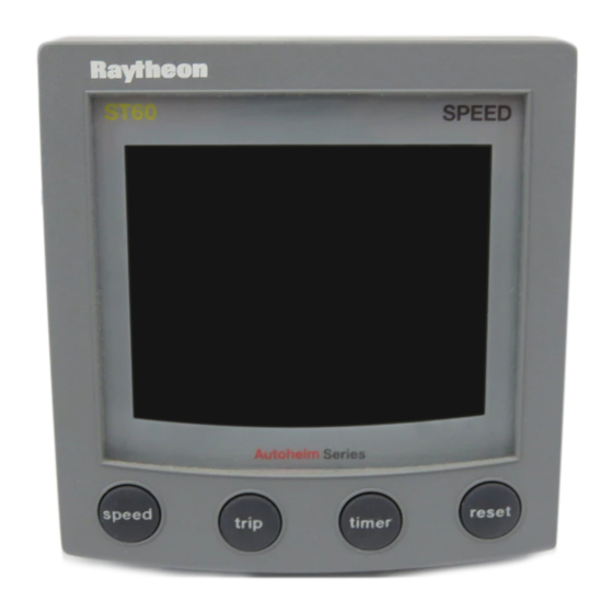
Page 5: Chapter 1. St60 Speed Instrument
It is also recommended a new case seal (10) is fitted on reassembly. Self-test procedure The ST60 Speed instrument has built-in self-test functions to aid fault diagnosis. To access self-test mode, press Key 1 and Key 4 together for 4 seconds. When the unit beeps, immediately press Key 3 and Key 4 together momentarily. -
Page 6: Self-Test Stage 4
Part 1. ST60 Instruments – Chapter 1. Speed No fail codes are generated since stage 2 is an audio/visual check. The following can, however, be used as a guide to isolate a problem: Failure Mode Action No illumination Check TR14, TR13, TR15 and associated components. -
Page 7: St60 Speed Spare Parts List
Part 1. ST60 Instruments – Chapter 1. Speed ST60 Speed spare parts list The item numbers refer to Figure 1: ST60 Digital instrument exploded view Item Spare/Accessory Description Part No. Comments Facia bezel A25001 – Suncover, standard A25004 Not illustrated... -
Page 8: St60 Speed Pcb Details
Part 1. ST60 Instruments – Chapter 1. Speed ST60 Speed PCB details Input/Output signals (refer to Figure 2. ST60 Speed circuit diagram) Rear case Signal Description connection A (Red) BATT+_2 Nominal 12V DC supply B (Screen) BATT-_2 C (Yellow) STALK_2... -
Page 9: St60 Speed Circuit Diagram
Part 1. ST60 Instruments – Chapter 1. Speed ST60 Speed circuit diagram Figure 2. ST60 Speed circuit diagram ST60 Instruments Service Manual 83142-1 5... -
Page 10: St60 Speed Pcb Layout
Part 1. ST60 Instruments – Chapter 1. Speed ST60 Speed PCB layout Taken from Drawing No: 4315-004 Issue: D Date: 01-10-98 D4451-1 6 ST60 Instruments Service Manual 83142-1... -
Page 11: St60 Speed Pcb Component List
Part 1. ST60 Instruments – Chapter 1. Speed ST60 Speed PCB component list ST60 SPEED Digital Taken from Drawing No: 4315-004 Issue: D Date: 01-10-98 D4452-1 ST60 Instruments Service Manual 83142-1 7... - Page 12 Part 1. ST60 Instruments – Chapter 1. Speed 8 ST60 Instruments Service Manual 83142-1...
-
Page 13: Chapter 2. St60 Depth Instrument
It is also recommended a new case seal (10) is fitted on reassembly. Self-test procedure The ST60 Depth instrument has built-in self-test functions to aid fault diagnosis. To access self-test mode, press Key 1 and Key 4 together for 4 seconds. When the unit beeps, immediately press Key 3 and Key 4 together momentarily. -
Page 14: Self-Test Stage 4
Part 1. ST60 Instruments – Chapter 2. Depth No fail codes are generated since stage 2 is an audio/visual check. The following can, however, be used as a guide to isolate a problem: Failure Mode Action No illumination Check TR14, TR13, TR15 and associated components. -
Page 15: St60 Depth Spare Parts List
Part 1. ST60 Instruments – Chapter 2. Depth ST60 Depth spare parts list The item numbers refer to Figure 1: ST60 Digital instrument exploded view Item Spare/Accessory Description Part No. Comments Facia bezel A25001 – Suncover,standard A25004 Not illustrated Keypad, Depth... -
Page 16: St60 Depth Pcb Details
Part 1. ST60 Instruments – Chapter 2. Depth ST60 Depth PCB details Input/Output signals (refer to Figure 3. ST60 Depth circuit diagram) Rear case Signal Description connection A (Red) BATT+_2 Nominal 12V DC supply B (Screen) BATT-_2 C (Yellow) STALK_2... -
Page 17: St60 Depth Circuit Diagram
Part 1. ST60 Instruments – Chapter 2. Depth ST60 Depth circuit diagram Figure 3. ST60 Depth circuit diagram ST60 Instruments Service Manual 83142-1 13... -
Page 18: St60 Depth Pcb Layout
Part 1. ST60 Instruments – Chapter 2. Depth ST60 Depth PCB layout ST60 DEPTH Digital Taken from Drawing No: 4316-003 Issue: D Date: 01-10-98 D4454-1 14 ST60 Instruments Service Manual 83142-1... -
Page 19: St60 Depth Pcb Component List
Part 1. ST60 Instruments – Chapter 2. Depth ST60 Depth PCB component list ST60 DEPTH Digital Taken from Drawing No: 4316-003 Issue: D Date: 01-10-98 D4455-1 ST60 Instruments Service Manual 83142-1 15... - Page 20 Part 1. ST60 Instruments – Chapter 2. Depth 16 ST60 Instruments Service Manual 83142-1...
-
Page 21: Chapter 3. St60 Multi Instrument
It is also recommended a new case seal (10) is fitted on reassembly. Self-test procedure The ST60 Multi instrument has built-in self-test functions to aid fault diagnosis. To access self-test mode, press Key 1 and Key 4 together for 4 seconds. When the unit beeps, immediately press Key 3 and Key 4 together momentarily. -
Page 22: Nmea I/O Testing
Part 1. ST60 Instruments – Chapter 3. Multi No fail codes are generated since stage 2 is an audio/visual check. The following can, however, be used as a guide to isolate a problem: Failure Mode Action No illumination Check TR14, TR13, TR15 and associated components. -
Page 23: St60 Multi Spare Parts List
Part 1. ST60 Instruments – Chapter 3. Multi ST60 Multi spare parts list The item numbers refer to Figure 1: ST60 Digital instrument exploded view Item Spare/Accessory Description Part No. Comments Facia bezel A25001 – Suncover,standard A25004 Not illustrated Keypad, Multi... -
Page 24: St60 Multi Pcb Details
Part 1. ST60 Instruments – Chapter 3. Multi ST60 Multi PCB details Input/Output signals (refer to Figure 4. ST60 Multi circuit diagram) Rear case Signal Description connection A (Red) BATT+_2 Nominal 12V DC supply B (Screen) BATT-_2 C (Yellow) STALK_2... -
Page 25: St60 Multi Circuit Diagram
Part 1. ST60 Instruments – Chapter 3. Multi ST60 Multi circuit diagram Figure 4. ST60 Multi circuit diagram ST60 Instruments Service Manual 83142-1 21... -
Page 26: St60 Multi Pcb Layout
Part 1. ST60 Instruments – Chapter 3. Multi ST60 Multi PCB layout ST60 MULTI Digital Taken from Drawing No: 4321-002 Issue: D Date: 01-10-98 D4460-1 22 ST60 Instruments Service Manual 83142-1... -
Page 27: St60 Multi Pcb Component List
Part 1. ST60 Instruments – Chapter 3. Multi ST60 Multi PCB component list ST60 MULTI Digital D4461-1 Taken from Drawing No: 4321-002 Issue: D Date: 01-10-98 ST60 Instruments Service Manual 83142-1 23... - Page 28 Part 1. ST60 Instruments – Chapter 3. Multi 24 ST60 Instruments Service Manual 83142-1...
-
Page 29: Chapter 4. St60 Tridata Instrument
It is also recommended a new case seal (10) is fitted on reassembly. Self-test procedure The ST60 Tridata instrument has built-in self-test functions to aid fault diagnosis. To access self-test mode, press Key 1 and Key 4 together for 4 seconds. When the unit beeps, immediately press Key 3 and Key 4 together momentarily. -
Page 30: Self-Test Stage 4
Part 1. ST60 Instruments – Chapter 4. Tridata No fail codes are generated since stage 2 is an audio/visual check. The following can, however, be used as a guide to isolate a problem: Failure Mode Action No illumination Check TR14, TR13, TR15 and associated components. Check all LEDs. -
Page 31: St60 Tridata Spare Parts List
Part 1. ST60 Instruments – Chapter 4. Tridata ST60 Tridata spare parts list The item numbers refer to Figure 1: ST60 Digital Instrument exploded view Item Spare/Accessory Description Part No. Comments Facia bezel A25001 – Suncover,standard A25004 Not illustrated Keypad, Tridata... -
Page 32: St60 Tridata Pcb Details
Part 1. ST60 Instruments – Chapter 4. Tridata ST60 Tridata PCB details Input/Output signals (refer to Figure 5. ST60 Tridata circuit diagram) Rear case Signal Description connection A (Red) BATT+_2 Nominal 12V DC supply B (Screen) BATT-_2 C (Yellow) STALK_2... -
Page 33: St60 Tridata Circuit Diagram
Part 1. ST60 Instruments – Chapter 4. Tridata ST60 Tridata circuit diagram Figure 5. ST60 Tridata circuit diagram ST60 Instruments Service Manual 83142-1 29... -
Page 34: St60 Tridata Pcb Layout
Part 1. ST60 Instruments – Chapter 4. Tridata ST60 Tridata PCB layout ST60 TRIDATA Digital Taken from Drawing No: 4317-002 Issue: E Date: 09-10-98 D4457-1 30 ST60 Instruments Service Manual 83142-1... -
Page 35: St60 Tridata Pcb Component List
Part 1. ST60 Instruments – Chapter 4. Tridata ST60 Tridata PCB component list ST60 TRIDATA Digital D4458-1 Taken from Drawing No: 4317-002 Issue: E Date: 09-10-98 ST60 Instruments Service Manual 83142-1 31... - Page 36 Part 1. ST60 Instruments – Chapter 4. Tridata 32 ST60 Instruments Service Manual 83142-1...