Table of Contents
Advertisement
Quick Links
Advertisement
Table of Contents

Related Manuals for Partner CD-70


Summary of Contents for Partner CD-70
- Page 1 CD-70 Utility User Manual...
-
Page 2: Table Of Contents
Table of Contents 1 1 1 1 P R E F A C E P R E F A C E P R E F A C E P R E F A C E ....... . . -
Page 3: Installation Guide
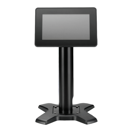
1 PREFACE The Virtual Line Display Utility helps to prepare Partner Tech CD-70 as a customer display and/or a digital signage display. The CD-70 Virtual Line Display Utility commands are identical to that on CD-7220 so customers can adopt existing commands directly on CD-70 without re-designing the software again. - Page 4 Fig. 2 Fig. 3 Fig. 4...
- Page 5 Fig. 5 Fig. 6 Fig. 7...
- Page 6 Fig. 8 Fig. 9 Fig. 10...
-
Page 7: Initial Comport Setup Guide
Fig. 11 Fig. 12 3.2 Initial Comport Setup Guide The default Virtual Line Display Utility will install the driver that occupies both COM 40 and COM 50 ports. Users can change the COM port to any available COM PORT by using the Line Display Tools. Please follow below steps to change the COM port: A. - Page 8 Fig. 14 B. Typed the new COM Port Number (For example COM2) into “New Port Name” and click on the “Rename” button to change the COM port. The pop up message will shown like Fig. 15, please choose “Continue” if it correct, then another pop-up message as shown on Fig.
- Page 9 Fig. 18 B. The default setting of Virtual Line Display Utility is shown as the Fig. 19. (Text mode 20x2, Display style 9, image transition time 3 seconds) Fig. 19 C. You can find a miniature icon of the utility on the task bar, like Fig.20. By double clicking the icon, the utility (Fig. 19) will pop up.
-
Page 10: Text Mode
4.1 Text Mode Text Mode has “Display 20x2” and “Display 20x6” modes A. Display 20x2: Choose this mode will have 2 lines of 20 characters per line display. Fig. 22 B. Display 20x6: Choose this mode will have 6 lines of 20 characters per line display. Fig. -
Page 11: Video
4.2 Video You can manage the videos files through add, delete, or delete all as shown on Fig. 24. The default supported video format is shown below: A. Default video format supported for Windows XP is mpeg/wav/avi. Video format depends on the codec installed on Windows Media Player. -
Page 12: Display Style
Fig. 25 4.4 Display Style Display Style has 14 styles as shown on Table 1. You can choose the style on Fig. 26 menu. By clicking “Preview”, you can preview the display setting result. Fig. 26... - Page 13 Fig. 27 Table 1. Display Style Layout List 1. Full Video 2. Full Image 3. Top Text + Image 4. Bottom Text + Image...
- Page 14 5. Top Text + Video 6. Bottom Text + Video 7. Top Text + (L) Video 16:9 + (R) Image 8. Top Text + (R) Video 16:9 + (L) Image 9. Bottom Text + (L) Video 16:9 + (R) Image 10.
-
Page 15: Auto Display On The Second Display
14. Bottom Text + (R) Video 4:3 + (L) Image 4.5 Auto display on the second display Choose this setting, the display screen will play on CD-70 by this default setting. 4.6 Display when the system start Choose this setting , the video and image will automatically starts when OS starts up. -
Page 16: Advance
4.8 Advance You can set demo message and background image by click on “Advance” icon. The suggestion image ratio for each line is 800x65. If the image is bigger than this suggested image ratio, the background image will cut the image to 800x65 from left to right and from top to bottom. -
Page 17: Reset Port
Fig. 31 4.10 OK When you click on the “OK” icon, the setting will be saved and the video & image will start showing on CD-70. 4.11 Exit Virtual Line Display Utility Please find the icon on task menu bar like Fig. 32. Click the mouse right key, the quick menu will shown like Fig. - Page 18 Fig 32 Fig. 33 5 Uninstall the Virtual Line Display Utility A. Click on “Virtual Line Display” on the Start menu; then select the “Uninstall Virtual Line Display” process to uninstall this utility. Fig. 34 B. Follow the uninstall process as shown below: Fig.
- Page 19 Fig. 36 Fig. 37 Fig. 38...
-
Page 20: Appendix
APPENDIX 1 Commands 1.1 SYSTEM COMMAND DETAILS 1.1.1 Command type select Change command type STX 05 C n ETX ASCII Format STX 05 C n ETX Dec. Format [02][05][67] n [03] Hex. Format [02h][05h] [43h] n [03h] 30h 3 7h ≦... -
Page 21: Run Demo Message
m = data message; the maximum data character is under 200 1.1.4 Run Demo message Run demo message STX 05 D 08 ETX ASCII Format STX 05 D 08 ETX Dec. Format [02][05][68][08][03] Hex. Format [02h][05h][44h][08][03h] Description Run demo message for the display 1.2 CD 5220-II STAND AND MODE COMMAND Command Code description (hex) -
Page 22: Adm787/788 Command List
clear display screen, and clear string mode clear cursor line, and clear string mode Table 6-1 (REMARK) * While using command "ESC QA" or "ESC QB", these two commands can be used with terminal printer: TP2688 or TP3688 * While using command "ESC QA" or "ESC QB", other commands can not be used except when using command "CLR" or "CAN" to change operating mode. * When using command "ESC QD", the upper line message will scroll continuously until a new command is received, it will then clear the upper line and move the cursor to the upper left-end position. -
Page 23: Utc Enhanced Mode Command List
vertical scroll mode ESC d 1B 64 change to UTC enhanced mode clear display Table 6-5 1.5 UTC enhanced mode command list Command Code description (hex) Function description ESC u A ..CR 1B 75 41 [ data x 40] 0D upper line display ESC u B ..CR 1B 75 42 [ data x 40] 0D... -
Page 24: Epson Esc/Pos Command List
EPSON ESC/POS command list Command Code description(hex) Function description move cursor right move cursor left US LF 1F 0A move cursor up move cursor down US CR 1F 0D move cursor to right-end position move cursor to left-end position move cursor to home position US B 1F 42 move cursor to bottom position... - Page 25 Hex. Format [1Bh][13h] Description Change the display mode to the horizontal mode. In this mode, the extend of the cursor activity is bond by predefined range, limited to the upper line. (Please refer to Set or cancel window command), where the default window is the whole upper line. Once the cursor activity reached the end of the range, the characters that comes there after will push displayed characters forward from behind.
- Page 26 ASCII Format ESC [ C Dec. Format [027][091][067] Hex. Format [1Bh][5Bh][43h] ASCII Format Dec. Format [009] Hex. Format [09h] Description Move the cursor to the right. When the cursor reached the right-end, this command operates differently depending on the display mode. 1.
- Page 27 ASCII Format Dec. Format [011] Hex. Format [0Bh] Description The cursor will move to the left-end position of the upper line /Move cursor to left-most position/ ESC [ L /Move cursor to left-most position/ ASCII Format ESC [ L Dec. Format [027][091][076] Hex.
-
Page 28: Customer Display Mode 20X2 Expand Command Details
[1Bh][57H][01h][x1][x2][y] Description Reset the window on the display. When s = 0, window is cancelled (values: x1, x2, and y are not required.) When s = 1 the window will be reset (values: x1, x2, and y are required.) The x1 and x2 set the position of the left column and right column, respectively, of the window. - Page 29 Description When s and 10h equal 10h save image file path. When s= 1h, clear current run show image list and set new d1d2d3..dn image file path When s= 2h, append current run show image list d1d2d3..dn image file path When s= 11h, clear current run show image list and set new d1d2d3..dn image file path.
- Page 30 image file path. When s= 5h, 15h change display line five back ground image, use d1d2d3..dn image file path. When s= 6h, 16h change display line six back ground image, use d1d2d3..dn image file path. When s= 11h,12h13h…16h , the current image file path save and replace display line x back ground image /set media volume / ESC o n...