ABB ACS850 Hardware Manual
Drive modules
Hide thumbs
Also See for ACS850:
- Manual (370 pages) ,
- Firmware manual (260 pages) ,
- Quick start up manual (196 pages)

Related Manuals for ABB ACS850


Summary of Contents for ABB ACS850
- Page 1 ACS850 Hardware Manual ACS850-04 Drive Modules (200 to 500 kW, 250 to 600 hp) Phone: 800.894.0412 - Fax: 888.723.4773 - Web: www.clrwtr.com - Email: info@clrwtr.com...
-
Page 2: List Of Related Manuals
List of related manuals Manual Code (EN) STANDARD MANUALS ACS850-04 Hardware Manual 200 to 500 kW (250 to 600 hp) 3AUA0000026234 ACS850 Standard Control Program Firmware Manual 3AUA0000045497 ACS850 Quick Start-up Guide (Standard Control Program) 3AUA0000045498 ACS850 Control Panel User's Guide... - Page 3 ACS850-04 Drive Modules 200 to 500 kW (250 to 600 hp) Hardware Manual 3AUA0000026234 Rev B EN EFFECTIVE: 26.6.2009 © 2009 ABB Oy. All Rights Reserved. Phone: 800.894.0412 - Fax: 888.723.4773 - Web: www.clrwtr.com - Email: info@clrwtr.com...
- Page 4 Phone: 800.894.0412 - Fax: 888.723.4773 - Web: www.clrwtr.com - Email: info@clrwtr.com...
-
Page 5: Table Of Contents
What the ACS850-04 is ........ - Page 6 Planning the cabinet installation What this chapter contains ............35 Basic requirements for the cabinet .
- Page 7 Checking the compatibility of the motor and drive ........58 Protecting the motor insulation and bearings .
- Page 8 Checking the combatibility with IT (ungrounded) and TN (corner grounded) systems ...78 Connecting the power cables ............79 Connection diagram .
- Page 9 Maintenance What this chapter contains ............103 Maintenance intervals .
- Page 10 Compliance with the EN 61800-3:2004 ..........124 Definitions .
- Page 11 Providing feedback on ABB Drives manuals ........
-
Page 12: Table Of Contents
Table of contents Phone: 800.894.0412 - Fax: 888.723.4773 - Web: www.clrwtr.com - Email: info@clrwtr.com... -
Page 13: Safety Instructions
Safety instructions What this chapter contains This chapter contains the safety instructions which you must follow when installing, operating and servicing the drive. If ignored, physical injury or death may follow, or damage may occur to the drive, motor or driven equipment. Read the safety instructions before you work on the unit. -
Page 14: Safety In Installation And Maintenance
Safety in installation and maintenance Electrical safety These warnings are intended for all who work on the drive, motor cable or motor. WARNING! Ignoring the following instructions can cause physical injury or death, or damage to the equipment: • Only qualified electricians are allowed to install and maintain the drive. •... -
Page 15: Grounding
Grounding These instructions are intended for all who are responsible for the grounding of the drive. WARNING! Ignoring the following instructions can cause physical injury, death, increased electromagnetic interference and equipment malfunction: • Ground the drive, motor and adjoining equipment to ensure personnel safety in all circumstances, and to reduce electromagnetic emission and interference. -
Page 16: Permanent Magnet Motor Drives
Permanent magnet motor drives These are additional warnings concerning permanent magnet motor drives. Ignoring the instructions can cause physical injury or death, or damage to the equipment. WARNING! Do not work on the drive when the permanent magnet motor is rotating. Also, when the supply power is switched off and the inverter is stopped, a rotating permanent magnet motor feeds power to the intermediate circuit of the drive and the supply connections become live. -
Page 17: General Safety
General safety These instructions are intended for all who install and service the drive. WARNING! Ignoring the following instructions can cause physical injury or death, or damage to the equipment: • Handle the unit carefully. • The drive module is heavy 200 kg (441 lb). Lift it by the upper part only using the lifting lugs attached to the top of the unit. -
Page 18: Fiber Optic Cables
Fiber optic cables WARNING! Ignoring the following instructions can cause equipment malfunction and damage to the fiber optic cables: • Handle the fiber optic cables with care. When unplugging optic cables, always grab the connector, not the cable itself. Do not touch the ends of the fibers with bare hands as the fiber is extremely sensitive to dirt. -
Page 19: Safe Start-Up And Operation
Safe start-up and operation General safety These warnings are intended for all who plan the operation of the drive or operate the drive. WARNING! Ignoring the following instructions can cause physical injury or death, or damage to the equipment: • Before adjusting the drive and putting it into service, make sure that the motor and all driven equipment are suitable for operation throughout the speed range provided by the drive. - Page 20 Safety instructions Phone: 800.894.0412 - Fax: 888.723.4773 - Web: www.clrwtr.com - Email: info@clrwtr.com...
-
Page 21: Introduction To The Manual
Introduction to the manual What this chapter contains This chapter describes the intended audience and contents of the manual. It contains a flowchart of steps in checking the delivery, installing and commissioning the drive. The flowchart refers to chapters/sections in this manual and other manuals. -
Page 22: Categorization By Option Code
Planning the electrical installation instructs in the motor and cable selection, protections and cable routing. Electrical installation instructs in how to wire the drive. Installation checklist contains lists for checking the mechanical and electrical installation of the drive. Start-up describes the start-up procedure of the drive. Fault tracing describes the fault tracing of the drive. - Page 23 If the drive module has been non-operational equipment are present and correct. for more than one year, the converter DC link capacitors need to be reformed. Ask ABB for Only intact units may be started up. instructions. Check the installation site.
-
Page 24: Terms And Abbreviations
Terms and abbreviations Term/Abbreviation Explanation Electromagnetic Compatibility Electromagnetic Interference FIO-01 Optional digital I/O extension FIO-11 Optional analogue I/O extension FIO-21 Optional analog and digital I/O extension FEN-01 Optional TTL encoder interface FEN-11 Optional absolute encoder interface FEN-21 Optional resolver interface FCAN-0x Optional CANopen adapter FDNA-0x... -
Page 25: Operation Principle And Hardware Description
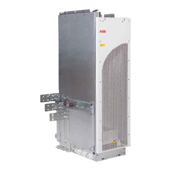
This chapter describes the operating principle and construction of the drive module in short. What the ACS850-04 is The ACS850-04 is a drive module for controlling asynchronous AC induction motors and permanent magnet synchronous motors. The main circuit of the drive module is shown below. -
Page 26: Product Overview
Product overview The degree of protection of the drive module is IP00. The module must be installed into a cabinet by the customer. Layout The components of the standard unit are shown below. Cables going to the JCU Control Unit and Drive module APOW board are coiled on the top of the Fastening points... - Page 27 The control unit layout is shown below (cover assembly and protective coverings of the slots removed). External 24 V power input Relay outputs +24VD Digital inputs Digital input/outputs Slots 1 and 2 for optional I/O extensions Analog inputs and encoder/resolver interface Analog outputs Drive-to-drive link...
-
Page 28: Alternative Output Busbar Configurations
DC busbars on the left-hand side. The output busbars can also be fastened on the short back side of the module. For more information, contact your local ABB representative. Output busbars on the short side of... -
Page 29: Component Placement
Component placement The component layout stickers of the drive module are shown below. The stickers show all possible components. Not all of them are present in each delivery or described here. Components that need to be changed regularly are listed below: Designation Component Cooling fan... -
Page 30: Power Connections And Control Interfaces
Power connections and control interfaces The diagram shows the power connections and control interfaces of the drive. Slot 1 / Slot 2 Control unit (JCU) FIO-01 (Digital I/O extension) FIO-11 (Analog I/O extension) FIO-21 (Analog and digital Slot 1 I/O extension) ) FEN-01 (TTL incremental Control panel or PC encoder interface) -
Page 31: Cables For Connecting The Control Unit To The Drive Module And Control Panel
Cables for connecting the control unit to the drive module and control panel The cables connectiong the drive module and control panel to the control unit are shown below. See pages for the actual connections. JCU Control Unit Drive module Shield APOW JRIB... -
Page 32: Type Designation Label
ACS850-04-430A-5. The optional selections are given thereafter, separated by plus signs eg, +E210. The main selections are described below. Not all selections are available for all types. For more information, refer to ACS850-04 Ordering Information (3AUA0000027760), available on request. Selection... - Page 33 Selection Alternatives Control panel and control J400 Control panel inserted onto the JCU Control Unit. Includes control panel mounting unit platform and internal cable. J410 Control panel with door mounting kit. Includes control panel mounting platform, IP54 cover and a 3-meter panel connection cable. J414 Control panel holder with cover and internal cable but no control panel.
- Page 34 Operation principle and hardware description Phone: 800.894.0412 - Fax: 888.723.4773 - Web: www.clrwtr.com - Email: info@clrwtr.com...
-
Page 35: Planning The Cabinet Installation
Note: The installation must always be designed and made according to applicable local laws and regulations. ABB does not assume any liability whatsoever for any installation which breaches the local laws and/or other regulations. Basic requirements for the cabinet Use a cabinet which: •... -
Page 36: Planning The Layout Of The Cabinet
Planning the layout of the cabinet Design a spacious layout to ensure easy installation and maintenance. Sufficient cooling air flow, obligatory clearances, cables and cable support structures all require space. Place the control board(s) away from: • the main circuit components such as contactor, switches and power cables •... -
Page 37: Layout Examples, Door Open
Layout examples, door open Layout examples for IP22 and IP54 cabinets are shown below IP54 IP22 1 Supporting frame of the cabinet 2 Air baffles that separate the cool and hot areas (leak-proof lead-throughs) 3 Input power cable including the protective conductors to cabinet grounding (PE) 4 Disconnector and fuses... -
Page 38: Arranging The Grounding Inside The Cabinet
• If fastening at the back is not possible or the cabinet will be exposed to vibration, the cabinet must be fastened at the top to the rear wall/roof. WARNING! Do not fasten the cabinet by electric welding. ABB does not assume any liability for damages caused by electric welding as the welding circuit may damage electronic circuits in the cabinet. -
Page 39: Planning The Cabinet Placement On A Cable Channel
Planning the cabinet placement on a cable channel Note the following when planning to place the cabinet on a cable channel: • The cabinet structure must be sturdy enough. If the whole cabinet base will not be supported from below, the cabinet weight will lie on the sections that the floor carries. - Page 40 • 360° high frequency grounding of the motor cable shields at their entries is recommended. The grounding can be implemented by a knitted wire mesh screening as shown below. Bare cable shield Cable ties Knitted wire mesh Lead-through plate Cable Cabinet bottom plate •...
-
Page 41: Planning The Grounding Of The Cable Shields At The Cabinet Lead-Through
Planning the grounding of the cable shields at the cabinet lead-through Follow the principle shown in the figure below when planning the grounding of the cable shields at the cabinet lead-through. To power terminals Strain relief Cable shield PE terminal of the cabinet or drive module EMC sleeve... - Page 42 • The drawing below shows two typical cabinet cooling solutions. The air inlet is at the bottom of the cabinet, while the outlet is at the top, either on the upper part of the door or on the roof. Air outlet Air inlet •...
-
Page 43: Preventing The Recirculation Of Hot Air
Preventing the recirculation of hot air Vertical air baffle A - A Air flow out Drive module Horizontal air baffle Drive module Air flow in max. 40°C (104 °F) Drive cubicle from side Drive cubicle from above Prevention the air recirculation outside the cabinet Prevent hot air circulation outside the cabinet by leading the outcoming hot air away from the area where the inlet air to the cabinet is taken. -
Page 44: Free Space At Top With High Air Inlet Gratings In The Cabinet Door
Free space at top with high air inlet gratings in the cabinet door The required free space at the top of the module is shown below when the air inlet gratings in the cabinet door are as high as the grating of the module. See also page 45. -
Page 45: Free Space At The Side And Front Of The Drive Module
• 150 mm (5.91 in.) with air inlets at the lower cooling. part of the cabinet only. Other installation positions Contact your local ABB representative. Planning the cabinet installation Phone: 800.894.0412 - Fax: 888.723.4773 - Web: www.clrwtr.com - Email: info@clrwtr.com... -
Page 46: Planning The Placement Of The Control Panel
Planning the placement of the control panel Note the following alternatives when planning the placement of the control panel: • The control panel can be snapped on the control unit of the drive. See page 28. • The control panel can be mounted onto the cabinet door using the control panel mounting kit (+J410). -
Page 47: Mechanical Installation
Mechanical installation What this chapter contains This chapter describes how to install the drive module into a cabinet. First, before- installation information is given, such as required tools, moving the unit and checking the delivery. Then, the mechanical installation procedure is described. Safety WARNING! The drive module is heavy 200 kg (441 lb). -
Page 48: Checking The Installation Site
Checking the installation site The material below the drive must be non-flammable and strong enough to carry the weight of the drive. See chapter Technical data for the allowed operating conditions. Required tools • Set of screw drivers • Torque wrench with a 500 mm (20 in.) or 2 × 250 mm (2 × 10 in.) long extension •... -
Page 49: Checking The Delivery
Unpack the package as follows: • Cut the bands (A). • Unpack the additional boxes (B). • Remove the sheathing by lifting it (C). • Fasten lifting hooks to the drive module lifting eyes (D) and lift the module to the installation place. -
Page 50: Fastening The Cable Lug Terminals To The Output Busbars
Fastening the cable lug terminals to the output busbars 1. Fasten the grounding terminals to the long side plates of the pedestal with screws. 2. Fasten the cable lug terminals to the busbars with screws. WARNING! See the next page for the screw sizes and tightening torques! Side view (cable lug terminals fastened) - Page 51 M10x25 M10x20 M10x25 Tightening torques: M10: 30...44 N·m (22...32 lbf·ft) M12: 50...75 N·m (37...55 lbf·ft) 2 pcs WARNING! Fasten the output busbars to the insulating supports with M10x20 screws when no cable lug terminal is connected, but with M10x25 screws when a cable lug terminal is connected as well.
-
Page 52: Fastening The Drive Module To The Cabinet Base
Fastening the drive module to the cabinet base 1. Fasten the front fastening bracket to the drive module pedestal with two screws. 2. Fasten the back fastening bracket onto the cabinet base with two screws. 3. Place the drive module on the cabinet base and push it so that the tabs of the fastening bracket enter the slots in the drive module pedestal. -
Page 53: Installing The Drive Control Unit
Installing the drive control unit The drive control unit can be fastened on a mounting plate through the fastening holes in its back or by using a DIN rail. The following drawings show the control unit with front cover but units without covers are installed in the same way. Mounting through the fastening holes 1. -
Page 54: Vertical Din Rail Mounting
Vertical DIN rail mounting 1. Fasten the latch (A) to the back of the control unit with four screws. 2. Click the control unit to the rail as shown below (B). 3aua0000038989 Mechanical installation Phone: 800.894.0412 - Fax: 888.723.4773 - Web: www.clrwtr.com - Email: info@clrwtr.com... -
Page 55: Horizontal Din Rail Mounting
Horizontal DIN rail mounting 1. Fasten the latches (A) to the back of the control unit with four screws. 2. Click the control unit to the rail as shown below (B). 3aua0000038989 Mechanical installation Phone: 800.894.0412 - Fax: 888.723.4773 - Web: www.clrwtr.com - Email: info@clrwtr.com... - Page 56 Mechanical installation Phone: 800.894.0412 - Fax: 888.723.4773 - Web: www.clrwtr.com - Email: info@clrwtr.com...
-
Page 57: Planning The Electrical Installation
Note: The installation must always be designed and made according to applicable local laws and regulations. ABB does not assume any liability whatsoever for any installation which breaches the local laws and/or other regulations. Furthermore, if the recommendations given by ABB are not followed, the drive may experience problems that the warranty does not cover. -
Page 58: Checking The Compatibility Of The Motor And Drive
Checking the compatibility of the motor and drive Use an AC induction motor or a permanent magnet synchronous motor with the drive. Several induction motors can be connected at a time but only one permanent magnet motor. Select the motor and drive according to the rating tables in chapter Technical Data. Use the DriveSize PC tool if the default load cycles are not applicable. -
Page 59: Requirements Table
To avoid damage to motor bearings: • select and install the cables according to the instructions given in the hardware manual • use insulated N-end (non-drive end) bearings and output filters from ABB according to the Requirements table below. Requirements table... - Page 60 Motor type Nominal AC line Requirement for voltage Motor insulation ABB du/dt filter, insulated N-end bearing and ABB common mode system filter < 100 kW 100 kW < P < 350 kW > 350 kW frame size > IEC 315 frame size <...
- Page 61 For motors with higher rated output than what is stated for the particular frame size in EN 50347 (2001) and for IP23 motors, the requirements of ABB random-wound motor series (for example M3AA, M3AP, M3BP) are given below. For non-ABB motor types, see the Requirements table above.
-
Page 62: Selecting The Power Cables
Û du/dt ------------ - (1/μs) Û du/dt ------------ - (1/μs) Cable length (m) Cable length (m) With du/dt filter Without du/dt filter Note 9: Sine filters protect the motor insulation system. Therefore, du/dt filter can be replaced with a sine filter. The peak phase-to-phase voltage with the sine filter is approximately 1.5 · U Note 10: Common mode filter is available as a plus code option (+E208) or as a separate kit (one box including three rings for one cable). -
Page 63: Typical Power Cable Sizes
A four-conductor system is allowed for input cabling, but shielded symmetrical cable is recommended. To operate as a protective conductor, the shield conductivity requirements according to IEC 60439-1 are shown below when the protective conductor is made of the same metal as the phase conductors: Cross-sectional area of the phase Minimum cross-sectional area of the conductors... -
Page 64: Typical Power Cable Sizes (Us)
Typical power cable sizes (US) Cable sizing is based on NEC Table 310-16 for copper wires, 75 °C (167 °F) wire insulation at 40 °C (104 °F) ambient temperature. Not more than three current- carrying conductors in raceway or cable or earth (directly buried). For other conditions, dimension the cables according to local safety regulations, appropriate input voltage and the load current of the drive. -
Page 65: Alternative Power Cable Types
Alternative power cable types The power cable types that can be used with the drive are represented below. Recommended Symmetrical shielded cable: three phase conductors A separate PE conductor is required if the conductivity and a concentric or otherwise symmetrically of the cable shield is <... -
Page 66: Conduit
Conduit Couple separate parts of a conduit together: bridge the joints with a ground conductor bonded to the conduit on each side of the joint. Bond the conduits also to the drive enclosure and motor frame. Use separate conduits for input power, motor, brake resistor, and control wiring. -
Page 67: Signals In Separate Cables
Control panel cable length and type In remote use, the cable connecting the control panel to the drive must not exceed 3 meters (10 ft). The cable type tested and approved by ABB is used in control panel option kits. -
Page 68: Diagram
Diagram A diagram of the cable routing is shown below. Motor cable Drive min 300 mm (12 in.) Power cable Input power cable Motor cable, brake cable 90 ° min 200 mm (8 in.) min 500 mm (20 in.) Control cables Separate control cable ducts 230 V 230 V... -
Page 69: Continuous Motor Cable Shield Or Enlosure For Equipment In The Motor Cable
2. Circuit breakers which have been tested by ABB with the drive can be used. Fuses must be used with other circuit breakers. Contact your local ABB representative for the approved breaker types and supply network characteristics. -
Page 70: Protecting The Motor And Motor Cable In Short-Circuits
WARNING! Due to the inherent operating principle and construction of circuit breakers, independent of the manufacturer, hot ionized gases may escape from the breaker enclosure in case of a short-circuit. To ensure safe use, special attention must be paid to the installation and placement of the breakers. Follow the manufacturer’s instructions. -
Page 71: Protecting The Drive Against Ground Faults
Protecting the drive against ground faults The drive is equipped with an internal ground fault protective function to protect the unit against ground faults in the motor and motor cable. This is not a personal safety or a fire protection feature. The ground fault protective function can be disabled with a parameter, refer to the appropriate Firmware Manual. -
Page 72: Implementing The Power-Loss Ride-Through Function
Safe Torque Off ACS850-04 connection on JCU XSTO:1 +24 V XSTO:2 Activation switch XSTO:3 XSTO:4 UDC+ Control circuit Output stage U2/V2/W2 (1 phase shown) Notes: • The contacts of the activation switch must open/close within 200 ms of each other. -
Page 73: Using Power Factor Compensation Capacitors With The Drive
Using power factor compensation capacitors with the drive Power factor compensation is not needed with AC drives. However, if a drive is to be connected in a system with compensation capacitors installed, note the following restrictions. WARNING! Do not connect power factor compensation capacitors or harmonic filters to the motor cables (between the drive and the motor). -
Page 74: Implementing A Bypass Connection
Alternative 3: When you have selected to use the scalar motor control mode in the drive, open the contactor as follows: 1. Give a stop command to the drive. 2. Open the contactor. WARNING! When you have the default motor control mode (DTC) in use, never open the output contactor while the drive rotates the motor. -
Page 75: Protecting The Contacts Of Relay Outputs
An example bypass connection is shown below. Switch Description Drive main contactor on/off control Motor power supply selection (drive or direct on line) Start when motor is connected on line Stop when motor is connected direct on line WARNING! Never connect the supply power to the drive output terminals U2, V2 and W2. -
Page 76: Connecting A Motor Temperature Sensor To The Drive I/O
Install the protective component as close to the inductive load as possible. Do not install protective components at the relay outputs. Varistor 230 VAC Relay output RC filter 230 VAC Relay output Diode 24 VDC Relay output Connecting a motor temperature sensor to the drive I/O WARNING! IEC 60664 requires double or reinforced insulation between live parts and the surface of accessible parts of electrical equipment which are either non- conductive or conductive but not connected to the protective earth. -
Page 77: Electrical Installation
Protective Earth conductor using a measuring voltage of 500 V DC. The insulation resistance of an ABB motor must exceed 10 Mohm (reference value at 25 °C or 77 °F). For the insulation resistance of other motors, please consult the manufacturer’s instructions. -
Page 78: Brake Resistor And Resistor Cable
Brake resistor and resistor cable Check the insulation of the brake resistor assembly (if present) as follows: 1. Check that the resistor cable is connected to the resistor, and disconnected from the drive output terminals R+ and R-. 2. At the drive end, connect the R+ and R- conductors of the resistor cable together. Measure the insulation resistance between the combined conductors and the PE conductor by using a measuring voltage of 1 kV DC. -
Page 79: Connecting The Power Cables
Connecting the power cables Connection diagram Drive module OUTPUT INPUT UDC+ V1 W1 V2 W2 (PE) (PE) External brake resistor, see page 137. Motor 1) For alternatives, see section Selecting the supply disconnecting device (disconnecting means) page 2) If shielded cable is used (not required but recommended) and the conductivity of the shield is < 50% of the conductivity of the phase conductor, use a separate PE cable (2) or a cable with a grounding conductor (3). -
Page 80: Input Cable Connection Procedure
Input cable connection procedure Connect the input cable phase conductors to the drive module terminals U1, V1 and W1 and the PE conductor to the PE terminal. Connect the twisted shield of the input cable to the PE terminal even if it is not used as the PE conductor. Removing the protective covering The protective covering on top of the drive module prevents dust from borings and grindings from entering the module when installing. -
Page 81: Motor Cable Connection Procedure
Motor cable connection procedure 1. Connect the twisted shield of the motor cable to the grounding terminal with a cable lug. 2. Connect the phase conductors to the cable lug terminals U2, V2 and W2. V2 U2 It is recommended to ground the motor cable shield 360° at the cabinet cable entry, see page 41. -
Page 82: Dc Connection
The UDC+ and UDC– terminals are intended for common DC configurations of a number of drives, allowing regenerative energy from one drive to be utilised by the other drives in motoring mode. Contact your local ABB representative for further instructions. -
Page 83: Removing The Cover Assembly
Removing the cover assembly The cover assembly needs to be removed before the installation of optional modules and the connection of control cabling. Follow this procedure to remove the cover assembly. The numbers refer to the illustrations below. • Press the tab (1) slightly with a screwdriver. •... -
Page 84: Fastening The Control Cable Clamp Plate
Fastening the control cable clamp plate Fasten the control cable clamp plate either to the top or base of the control unit with four screws as shown below. 0.7 N·m (6.2 lbf·in) Grounding the control unit If the control unit is not grounded through DIN rail mounting, connect the APOW cable grounding wire to the grounding terminal at the back top or bottom of the control unit. -
Page 85: Connecting The Control Unit To The Drive Module
Connecting the control unit to the drive module Connect the control unit to the drive module as follows. WARNING! Handle the fiber optic cables with care. When unplugging optic cables, always grab the connector, not the cable itself. Do not touch the ends of the fibers with bare hands as the fiber is extremely sensitive to dirt. -
Page 86: Connecting The Control Cables
2. Insert the fiber optic cables to the JRIB board terminals. 3. Connect the power supply cable coming from the drive module to the cable connected to the JRIB board terminals. APOW board JINT board JRIB board Connection table APOW JRIB X3: 1 X202: 1... -
Page 87: Default I/O Connection Diagram
Default I/O connection diagram XPOW Notes: +24VI External power input […] denotes default setting with ACS850 24 V DC, 1.6 A standard control program (Factory macro). See Firmware Manual for other macros. XRO1, XRO2, XRO3 *Total maximum current: 200 mA... -
Page 88: Jumpers
Jumpers DI/DIO grounding selector (located between XD24 and XDI) – Determines whether the DIGND (ground for digital inputs DI1…DI5) floats, or if it is connected to DIOGND (ground for DI6, DIO1 and DIO2). See the JCU isolation and grounding diagram on page 121. -
Page 89: External Power Supply For The Jcu Control Unit (Xpow)
External power supply for the JCU Control Unit (XPOW) External +24 V (minimum 1.6 A) power supply for the control unit can be connected to terminal block XPOW. Using an external supply is recommended if • the application requires fast start after connecting the drive to the main supply •... -
Page 90: Drive-To-Drive Link (Xd2D)
WARNING! As the inputs pictured above are not insulated according to IEC 60664, the connection of the motor temperature sensor requires double or reinforced insulation between motor live parts and the sensor. If the assembly does not fulfil the requirement, •... -
Page 91: Safe Torque Off (Xsto)
Safe torque off (XSTO) For the drive to start, both connections (OUT1 to IN1, and OUT2 to IN2) must be closed. By default, the terminal block has jumpers to close the circuit. Remove the jumpers before connecting an external Safe Torque Off circuitry to the drive. See page 71. -
Page 92: Routing The Control Cables
Routing the control cables Use shrink tubing or tape to contain strands Run cables through the cover mounting bracket Remove outer jacket of cable at clamp to expose cable shield. Tighten clamp to 1.5 N·m (13 lbf·in) Electrical installation Phone: 800.894.0412 - Fax: 888.723.4773 - Web: www.clrwtr.com - Email: info@clrwtr.com... -
Page 93: Connecting A Pc
Connecting a PC Connect the PC to terminal X7 on the control unit. Installing optional modules Mechanical installation Optional modules such as a fieldbus adapters, an I/O extensions and the pulse encoder interfaces are inserted in the optional module slot on the control unit. See page for the available slots. - Page 94 Electrical installation Phone: 800.894.0412 - Fax: 888.723.4773 - Web: www.clrwtr.com - Email: info@clrwtr.com...
-
Page 95: Installation Checklist
Installation checklist What this chapter contains This chapter contains a list for checking the mechanical and electrical installation of the drive. Go through the checklists below together with another person. Follow the Safety instructions on the first pages. Mechanical installation Cabinet construction Checks for cabinet construction are listed below. - Page 96 Busbars The types (Al/Cu) and cross-sections of busbars are correct. Busbars are intact and joint surfaces are clean. There are no metal scraps on the busbars that could cause a short-circuit. The placement and mounting of busbars is correct. The electrical connection of busbars. Check that the surfaces in electrical connections of aluminium and uncoated busbars are rubbed.
-
Page 97: Groundings And Protection
Electrical installation. Check The capacitors are reformed if stored over one year (ask local ABB representative for more information). The drive is grounded properly: 1) proper and properly tightenened PE connector, 2) proper galvanic connection between drive frame and cabinet (fastening points are unpainted). -
Page 98: Cooling And Driven Equipment
Cooling and driven equipment Checks for cooling conditions and motor and driven equipment before start-up are listed below. The ambient operating conditions are allowable. (See Technical data: Rating tables, Ambient conditions.) The cooling air will flow freely. The protective covering is removed from the top of the drive module. The motor and the driven equipment are ready for start. -
Page 99: Start-Up
Start-up What this chapter contains This chapter describes the start-up procedure of the drive. Start-up procedure Set-up of the drive program according to the start-up instructions given in the drive firmware manual. Perform the start-up tasks instructed by the cabinet-installer of the drive module. Start-up Phone: 800.894.0412 - Fax: 888.723.4773 - Web: www.clrwtr.com - Email: info@clrwtr.com... - Page 100 Start-up Phone: 800.894.0412 - Fax: 888.723.4773 - Web: www.clrwtr.com - Email: info@clrwtr.com...
-
Page 101: Fault Tracing
Fault tracing What this chapter contains This chapter describes the fault tracing possibilities of the drive. LEDs This table describes LEDs of the drive module. Where When the LED is lit JINT board V204 (green) +5 V voltage of the board is OK. V309 (red) Not in use. - Page 102 Fault tracing Phone: 800.894.0412 - Fax: 888.723.4773 - Web: www.clrwtr.com - Email: info@clrwtr.com...
-
Page 103: What This Chapter Contains
Replace with a new CR 2032 battery. Consult your local ABB Service representative for more details on the maintenance. On the Internet, go to ABB website and select Drive Services – Maintenance and Field Services. -
Page 104: Heatsink
See the appropriate Firmware Manual for the actual signal which indicates the running time of the cooling fan. For resetting the running time signal after a fan replacement, please contact ABB. Replacement fans are available from ABB. Do not use other than ABB specified spare parts. Maintenance... -
Page 105: Replacing The Cooling Fan Of The Module
Replacing the cooling fan of the module WARNING! Folow the safety instructions, page 14. Ignoring the instructions can cause physical injury or death, or damage to the equipment 1. Remove the front cover. 2. Disconnect the fan capacitor and power supply wires. 3. -
Page 106: Replacing The Drive Module
Replacing the drive module The drive module can be replaced by disconnecting the pedestal and busbars connected to it from the drive module and leaving the pedestal and busbars into the cabinet. Proceed as follows: WARNING! Follow the safety instructions, page 14. Ignoring the instructions can cause physical injury or death, or damage to the equipment 1. - Page 107 M10×25 combi, 30 N·m (22 lbf·ft) Pedestal when the module is removed Note: A drive module trolley is available from ABB. The trolley helps in removing heavy drive modules from a cabinet and in replacing the module. Maintenance Phone: 800.894.0412 - Fax: 888.723.4773 - Web: www.clrwtr.com - Email: info@clrwtr.com...
-
Page 108: Capacitors
It is not possible to predict a capacitor failure. Capacitor failure is usually followed by damage to the unit and an input cable fuse failure, or a fault trip. Contact ABB if capacitor failure is suspected. Replacements are available from ABB. Do not use other than ABB specified spare parts. -
Page 109: Replacing The Capacitor Pack
Replacing the capacitor pack WARNING! Follow the safety instructions, page 14. Ignoring the instructions can cause physical injury or death, or damage to the equipment 1. Remove the front cover, see (1) on page 105. Remove the profiled side plate. 2. -
Page 110: Memory Unit
M6×12 combi screw M6×12 combi, 8 N·m (6 lbf·ft) M10, 30 N·m (22 lbf·ft) Capacitor pack removed Memory unit When a drive module is replaced, the parameter settings can be retained by transferring the memory unit from the defective drive module to the new module. The memory unit is located in the JCU Control Unit, see page 27. -
Page 111: Technical Data
Note: To achieve the rated motor power given in the table, the rated current of the drive must be higher than or equal to the rated motor current. The DriveSize dimensioning tool available from ABB is recommended for selecting the drive, motor and gear combination for the required motion profile. -
Page 112: Ambient Temperature Derating
Ambient temperature derating In the temperature range +40…55 °C (+104…131 °F), the rated output current is derated by 1% for every added 1 °C (1.8 °F) as follows: Derating factor 1.00 0.85 Ambient temperature +40 °C +55 °C +104 °F +131 °F Altitude derating At altitudes from 1000 to 4000 m (3300 to 13123 ft) above sea level, the derating is 1% for every 100 m... -
Page 113: Calculation Example
2 · The calculated short-circuit current 9.7 kA is higher than the minimum short-circuit current of the drive gG fuse type OFAF3H500 (8280 A). -> The 500 V gG fuse (ABB Control OFAF3H500) can be used. Technical data Phone: 800.894.0412 - Fax: 888.723.4773 - Web: www.clrwtr.com - Email: info@clrwtr.com... -
Page 114: Fuse Tables
Fuse tables gG fuses Drive type Input Min. short- Fuse ACS850-04… current circuit current Manufacturer Type IEC size -430A-5 8280 2 900 000 ABB Control OFAF3H500 -521A-5 10200 4 000 000 ABB Control OFAF3H630 -602A-5 10200 4 000 000 ABB Control... -
Page 115: Quick Guide For Selecting Between Gg And Ar Fuses
(cable size, cable length, transformer size and fuse type) in the table fulfill the minimum requirements for the proper operation of the fuse. Drive type Cable type Supply transformer minimum apparent power S (kVA) ACS850-04… Copper Aluminum Maximum cable length with gG Maximum cable length with aR fuses... -
Page 116: Ul Class T And L Fuses
UL class T and L fuses Drive type Input Fuse current ACS850-04… Manufacturer Type UL class -430A-5 Bussmann JJS-500 -521A-5 Bussmann JJS-600 -602A-5 Ferraz A4BY800 -693A-5 Ferraz A4BY800 -720A-5 Ferraz A4BY800 Note 1: See also Implementing thermal overload and short-circuit protection... -
Page 117: Losses, Cooling Data And Noise
Losses, cooling data and noise Drive type Frame Air flow Heat dissipation Noise size /min BTU/Hr ACS850-04… -430A-5 1220 6850 22550 -521A-5 1220 7800 24420 -602A-5 1220 7600 27670 -693A-5 1220 8100 29550 -720A-5 1220 9100 31080 IP22 cabinet with no extra fan An IP22 cabinet should meet the following data to ensure efficient cooling of the drive module. -
Page 118: Terminal And Lead-Through Data For The Power Cables
Terminal and lead-through data for the power cables Input, motor and brake resistor cable terminal sizes (per phase), maximum accepted cable and tightening torques are given below. U1, V1, W1, U2, V2, W2, UDC+/R+, UDC-, R- Grounding PE Number of holes Max. -
Page 119: Brake Resistor Connection Data
Maximum recommended Type code (EMC Max. motor cable length motor cable length equipment) DTC control Scalar control 300 m (984 ft) 300 m (984 ft) +E210 * 100 m (328 ft) 100 m (328 ft) * Motor cable longer than 100 m (328 ft) is allowed but then the EMC Directive requirements may not be fulfilled. - Page 120 Digital inputs/outputs DIO1 Connector pitch 3.5 mm, wire size 1.5 mm and DIO2 As inputs: (XDIO:1 and XDIO:2) 24 V logic levels: “0” < 5 V, “1” > 15 V Input/output mode selection by : 2.0 kohm parameters. Filtering: 0.25 ms min. DIO1 can be configured as a As outputs: frequency input (0…16 kHz)
-
Page 121: Efficiency
Isolation and grounding XPOW diagram +24VI XRO1…XRO3 XD24 +24VD DIGND +24VD DIOGND DIIL XDIO DIO1 DIO2 +VREF -VREF AGND AI1+ Common mode voltage AI1- AI2+ between channels AI2- ± 20 V AO1+ AO1- AO2+ AO2- XD2D BGND XSTO OUT1 OUT2 Ground Efficiency Approximately 98% at nominal power level... -
Page 122: Ambient Conditions
Ambient conditions Environmental limits for the drive are given below. The drive is to be used in a heated, indoor, controlled environment. Operation Storage Transportation installed for stationary use in the protective package in the protective package Installation site altitude 0 to 4000 m (13123 ft) above sea level (above 1000 m [3281 ft]), see section... -
Page 123: Materials
EU. They must be removed and handled according to local regulations. For further information on environmental aspects and more detailed recycling instructions, please contact your local ABB distributor. Applicable standards The drive complies with the following standards. The compliance with the European Low Voltage Directive is verified according to standards EN 61800-5-1 and EN 60204-1. -
Page 124: Ce Marking
CE marking A CE mark is attached to the drive to verify that the unit follows the provisions of the European Low Voltage and EMC Directives. Compliance with the European Low Voltage Directive The compliance with the European Low Voltage Directive has been verified according to standards EN 61800-5-1 and EN 60204-1. -
Page 125: Category C3
Equipment 2. An EMC plan for preventing disturbances is drawn up for the installation. A template is available from the local ABB representative. 3. The motor and control cables are selected as specified in the Hardware Manual. 4. The drive is installed according to the instructions given in the Hardware Manual. -
Page 126: Ul Marking
Ambient conditions for specific limits. Brake chopper - ABB has brake choppers that, when applied with appropriately sized brake resistors, will allow the drive to dissipate regenerative energy (normally associated with quickly decelerating a motor). Proper application of the brake chopper is defined in chapter Resistor braking. -
Page 127: Dimension Drawings
Dimension drawings What this chapter contains This chapter contains dimension drawings of the drive modules as well as auxiliary components. Frame size G without pedestal (mm) Center of gravity 64801082_3/6 E Dimension drawings Phone: 800.894.0412 - Fax: 888.723.4773 - Web: www.clrwtr.com - Email: info@clrwtr.com... -
Page 128: Frame Size G With Busbars On The Left Side (Mm)
Frame size G with busbars on the left side (mm) Dimension drawings Phone: 800.894.0412 - Fax: 888.723.4773 - Web: www.clrwtr.com - Email: info@clrwtr.com... -
Page 129: Frame Size G Pedestal Busbars On The Long Side (Mm)
Frame size G pedestal busbars on the long side (mm) Bilateral output busbar 64801082_4/6 E Dimension drawings Phone: 800.894.0412 - Fax: 888.723.4773 - Web: www.clrwtr.com - Email: info@clrwtr.com... -
Page 130: Drive Control Unit (Jcu)
Drive control unit (JCU) Dimension drawings Phone: 800.894.0412 - Fax: 888.723.4773 - Web: www.clrwtr.com - Email: info@clrwtr.com... -
Page 131: Package
Package Dimension drawings Phone: 800.894.0412 - Fax: 888.723.4773 - Web: www.clrwtr.com - Email: info@clrwtr.com... -
Page 132: Dimension Drawings (Usa)
Dimension drawings (USA) Frame size G without pedestal (inches) Center of gravity 68440513_3/6 A (64801082.asm E) Dimension drawings Phone: 800.894.0412 - Fax: 888.723.4773 - Web: www.clrwtr.com - Email: info@clrwtr.com... -
Page 133: Frame Size G With Busbars On The Left Side (Inches)
Frame size G with busbars on the left side (inches) Dimension drawings Phone: 800.894.0412 - Fax: 888.723.4773 - Web: www.clrwtr.com - Email: info@clrwtr.com... -
Page 134: Frame Size G Pedestal Busbars On The Long Side (Inches)
Frame size G pedestal busbars on the long side (inches) Bilateral output busbar 68440513_4/6 A (64801082.asm E) Dimension drawings Phone: 800.894.0412 - Fax: 888.723.4773 - Web: www.clrwtr.com - Email: info@clrwtr.com... -
Page 135: Example Circuit Diagrams
Example circuit diagrams What this chapter contains This chapter shows an example circuit diagram for a cabinet-installed drive module. Example circuit diagrams Phone: 800.894.0412 - Fax: 888.723.4773 - Web: www.clrwtr.com - Email: info@clrwtr.com... -
Page 136: Example Circuit Diagram
Example circuit diagram This diagram is an example for the main wiring of a drive cabinet. Note that the diagram includes components which are not included in a basic delivery (* plus code options, ** other options, *** to be acquired by the customer). Example circuit diagrams Phone: 800.894.0412 - Fax: 888.723.4773 - Web: www.clrwtr.com - Email: info@clrwtr.com... -
Page 137: Resistor Braking
Energy consumption by the resistor losses lowers the voltage until the resistor can be disconnected. Hardware description The resistors available from ABB as add-on kits are built in an IP00 metal frame. 2×SAFUR and 4×SAFUR resistors are connected in parallel. Planning the braking system Selecting the brake circuit components 1. -
Page 138: Placing The Brake Resistors
2. Select a suitable drive and brake resistor combination for the application according to the rating table on page 141. Take also account of other factors in the drive selection. The braking power must be greater than or equal to the maximum power generated by the motor during braking: >... -
Page 139: Protecting The System In Fault Situations
Note: If an external brake chopper (outside the drive module) is used, a main contactor is always required. A thermal switch (standard in ABB resistors) is required for safety reasons. The cable must be shielded and not longer than the resistor cable. -
Page 140: Minimizing Electromagnetic Interference
IGBT semiconductors of the brake chopper. EMC compliance of the complete installation Note: ABB has not verified that the EMC requirements are fulfilled with external user-defined brake resistors and cabling. The EMC compliance of the complete installation must be considered by the customer. -
Page 141: Technical Data
400 seconds does not exceed E See page 137. Drive type Frame Braking power (drive + chopper) Brake resistor(s) size 5/60 s 10/60 s 30/60 s Type ACS850-04… Rcont (ohm) (kJ) (kW) br10 br30 brcont (kW) (kW) (kW) -
Page 142: Brake Resistor Connection Data
Example: max 5 s, 10 s or 30 s or P br10 br30 brcont No braking min. 60 s min. 60 s Brake resistor connection data Voltage over the resistor during braking is 1.35 · 1.2 · 415 V DC when the supply voltage is 380 to 415 VAC and 1.35 ·... -
Page 143: What This Chapter Contains
Description, installation and technical data of the FOCH filters See FOCH du/dt Filters Hardware Manual (3AFE68577519 [English]). Sine filters Contact your local ABB representative. Du/dt filters and sine filters Phone: 800.894.0412 - Fax: 888.723.4773 - Web: www.clrwtr.com - Email: info@clrwtr.com... - Page 144 Du/dt filters and sine filters Phone: 800.894.0412 - Fax: 888.723.4773 - Web: www.clrwtr.com - Email: info@clrwtr.com...
-
Page 145: Product And Service Inquiries
Address any inquiries about the product to your local ABB representative, quoting the type designation and serial number of the unit in question. A listing of ABB sales, support and service contacts can be found by navigating to ABB website and selecting Sales, Support and Service network.