Advertisement
Advertisement
Table of Contents

Summary of Contents for Murphy Cascade CD101
- Page 1 Cascade CD101 Auto-Start Controller Installation and Operations Manual 00-02-0594 04-16-10 Sections 40 & 75...
- Page 2 NEC and local codes. • Disconnect all electrical power to the machine. • Make sure the machine cannot operate during installation. • Follow all safety warnings of the machine manufacturer. • Please contact FW MURPHY immediately if you have any questions.
-
Page 3: Table Of Contents
Table of Contents Operating the Cascade ......................1 LED Status Light ........................2 Setting Up the Cascade ......................3 Modes of Operation ....................... 3 Installing the Cascade Auto-Start Controller ................. 4 Tools Needed ........................ 4 ... - Page 4 (NOTES)
-
Page 5: Operating The Cascade
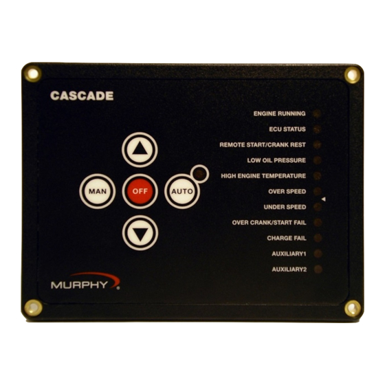
Operating the Cascade When power is first applied, all LEDs will flash indicating a Lamp Test function. To manually start the engine, press the “MAN” (Manual) button. The controller will initiate a normal start sequence. In MANUAL MODE, operating the “UP/DOWN” arrow keys will activate Aux outputs 1-4 if they are configured for SPEED UP / SPEED DOWN. -
Page 6: Led Status Light
LED Status Light Eleven LEDs separated into two banks (see “Fig. 1”) are provided on the faceplate. The LEDs Bank 1 includes 6 LEDs and Bank 2 includes 5. In Setup mode, these banks form a binary code to indicate either the controller setup configuration or error status, which is indicated by the last 8 (red) LEDs. -
Page 7: Setting Up The Cascade
Setting Up the Cascade To enter the SETUP MODE, first remove DC power to the Cascade controller for approximately 10 seconds. On the back of the controller are four DIP switches, set switch #1 to ON (see schematic at right) then restore DC power. The AUTO mode LED will blink to indicate that the Cascade is in the SETUP MODE. -
Page 8: Installing The Cascade Auto-Start Controller
Installing the Cascade Auto-Start Controller The Cascade controller offers automatic start/stop control with easy configuration for a broad number of engine driven applications. Tools Needed To install the Cascade, you will need: • #2 Philips (cross head) head screwdriver • Nut driver to fit #6-32x1/2”... -
Page 9: Recommended Wiring Practices
Recommended Wiring Practices Warning: The CASCADE is designed for pilot-duty use and its outputs are for control only. Wire the CASCADE controller with 18 gage stranded wire. Important: For applications involving automatic start equipment, we strongly recommend the installation of an appropriate Emergency Stop device. To help prevent electrical noise and voltage drop to the controller during cranking and preheat, wire the controller DC power connections directly to the cranking battery. -
Page 10: Typical Wiring Diagrams
Typical Wiring Diagrams Cascade – Basic Engine AC Sensing Speed Sections 40 & 75 00-02-0594 04-16-10 - 6 -... - Page 11 Cascade – Basic Mechanical Engine MPU Sensing Speed Sections 40 & 75 00-02-0594 04-16-10 - 7 -...
- Page 12 Cascade – Basic ECU Engine ECU Speed Sensing Sections 40 & 75 00-02-0594 04-16-10 - 8 -...
- Page 13 Inc/Dec Throttle (Manual), Line Fill Delay, Low Oil/Coolant Level, Preheat, Common Alarm Sections 40 & 75 00-02-0594 04-16-10 - 9 -...
- Page 14 Mechanical Engine MPU Source Throttling to Pressure, Low Liquid Level Shutdowns Warmup-Cooldown Output Sections 40 & 75 00-02-0594 04-16-10 - 10 -...
- Page 15 Mechanical Engine Winter/Summer Switch, Preheat Output & Timer Run & Idle Switch Output Sections 40 & 75 00-02-0594 04-16-10 - 11 -...
-
Page 16: Specifications
Specifications • Power input: 9-35VDC continuous - operates during total blackout for 2 sec. min. • Power consumption: Sleep Mode (Manual): 1mA typical;(Automatic) 4mA typical. Running Mode (Manual): 20mA typical; (Automatic): 24mA typical. • Operating/Storage temperature: -40 to 85°C; (-40 to 185°F). •... -
Page 17: Tables
Sections 40 & 75 00-02-0594 04-16-10 - 13 -... - Page 18 Sections 40 & 75 00-02-0594 04-16-10 - 14 -...
- Page 19 Sections 40 & 75 00-02-0594 04-16-10 - 15 -...
- Page 20 Sections 40 & 75 00-02-0594 04-16-10 - 16 -...
- Page 21 Sections 40 & 75 00-02-0594 04-16-10 - 17 -...


