Table of Contents
Advertisement
Advertisement
Table of Contents

Related Manuals for Bosch ABS M4


Summary of Contents for Bosch ABS M4
- Page 1 ABS M4 Manual V 1.2 1/11/2018...
-
Page 2: Table Of Contents
9.2 Features of the Programming and Diagnosis Software ....................27 10 Appendix ................................38 10.1 Startup Checklist .................................... 38 10.2 CAN Protocol ....................................40 11 Offer Drawing: Hydraulic Power Unit with attached Control Unit .............. 43 2 / 54 ABS M4 Manual Bosch Motorsport... - Page 3 14 Offer Drawing: Wheel Speed Sensor ....................... 46 15 Offer Drawing: Gyro/Acceleration Sensor ...................... 47 16 Wiring Diagram ..............................48 17 Wiring Diagram ABS M4 Clubsport ......................... 49 18 Wiring Harness ..............................50 19 Wiring Harness Clubsport ..........................51 Bosch Motorsport...
-
Page 4: System Overview
1 | System Overview System Overview 4 / 54 ABS M4 Manual Bosch Motorsport... -
Page 5: Before Use
Safety Information The ABS M4 Kit was developed for use by professionals and requires in‐depth knowledge of automobile technology and experience in motorsport. Using the system does not come without its risks. -
Page 6: Principle Of Operation
With this, the driver can choose the best setting for his vehi‐ cle. Furthermore, the ABS M4 provides the opportunity to program two individu‐ al control settings for you vehicle. For calibration drives, the ABS function can be deactivated separately, whereby all ABS sensor signals are transmitted and pro‐... - Page 7 You can switch off the ABS functions by switching to position 12. This can be very helpful, e.g. for calibration of the brake balance adjuster. All ABS sensor signals will still be communicated. Every older ABS M4 can be updated to this function. During warm‐up we recommend to choose position 12. Since soft‐...
- Page 8 You can switch the system ON or OFF by moving the switch in the cockpit for one time. ▪ Reset the System with a switch in the cockpit You can reset the system by moving the switch to the position OFF and then directly again ON. 8 / 54 ABS M4 Manual Bosch Motorsport...
-
Page 9: Technical Data
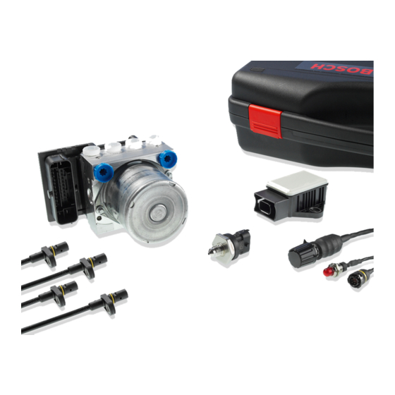
Brake light switch Outputs ABS warning light (MIL) Communication CAN interface Content of Kit and Weights Hydraulic unit with attached ECU About 1,850 g Pressure sensor About 40 g Yaw/acceleration sensor About 60 g Bosch Motorsport ABS M4 Manual 9 / 54... -
Page 10: Optional Accessories
F 02U V01 928‐01 Field of application ABS for front‐wheel, rear‐wheel or four‐ wheel drive racing cars Part numbers ABS M4‐Package 1 (incl. wiring harness with F 02UV00 289‐01 motorsport connectors, individual layout depending on customer requirements, wheel speed sensors with production‐type connectors) ABS M4‐Package 2 (incl. -
Page 11: Adaptations To Your Vehicle
DF11 or similar to function correctly. These sensor types are used in new vehicles for ABS and ESP® systems and can be carried over for the ABS M4. The signal level of conventional speed sensors, as found in old series‐production ABS sys‐... - Page 12 The splitter provides an input signal like as it is shown in the diagram in chapter Wheel Speed Signal Splitter 16]. This module can be used, for traction control, display and gear units. For ordering information see al‐ so Wheel Speed Signal Splitter 16]. 12 / 54 ABS M4 Manual Bosch Motorsport...
-
Page 13: Included In The Kit
Parts Overview Kit 2 ABS M4 Kit 2 includes all the parts from Kit 1, with the exception of a different wiring harness with motorsport connectors for the wheel speed sensors. Bosch Motorsport... -
Page 14: Parts Overview Kit Clubsport
F 02U V00 543‐12 DF11i) ABS M4 Kit includes all parts from Kit 1, but a different wiring harness, which cannot be modified. By default the wiring harness includes a 60 Ohm terminal re‐ sistance, which can be replaced customer specific by a 120 Ohm or deleted com‐... -
Page 15: Connectors Overview Kit 2
F 02U B00 435‐01 Connectors Overview Kit 2 ABS M4 Kit 2 with part number F 02U V00 290‐01 includes a harness with all the connectors from Kit 1, with the exception of different connectors for the wheel speed sensors:... -
Page 16: Optional Accessories
MSA Box II ABS M4 communicates with your laptop via the MSA Box II. It has a USB connec‐ tion to the laptop and a motorsport connector to interface with the ABS M4 wire harness. -
Page 17: Data Logger C 70
All ABS M4 data can be stored on a CAN‐compatible data logger. We recom‐ mend to use our C 70 data logger for storing and analyzing ABS M4 data. Bosch Motorsport provides a standardized CAN log in DBC format for analyzing recorded CAN data. -
Page 18: Assembling The Parts
Secure the hy‐ draulic power unit to the assembly plate supplied with the ABS M4 Kit using the three M6x1 screw threads on the underside of the casing. To reduce vibration, rubber pads should be fitted between the assembly plate and the vehicle chassis. -
Page 19: Brake Pressure Sensor
Bosch Motorsport ABS M4 needs special edited wheel speed signals, which are supplied only from active speed sensors like e.g. from Bosch DF11‐family. These double hall sensors operate on the differential principle. The ABS M4 needs all Bosch Motorsport ABS M4 Manual... -
Page 20: Encoder Wheel
You should therefore only use the speed sensors as supplied in the ABS M4 ‐Kit (see section ‐‐‐ MISSING LINK ‐‐‐). We can offer different DF11 versions on request for specific vehicle designs. Existing mounted wheel speed sensors can be tested and approved by us. -
Page 21: Abs Map Switch
The included wiring harness is structured in such a way that the power supply to the ABS warning light (MIL) is branched off before the main switch for ABS M4 (terminal 30). This is the only way to ensure that the ABS warning light (MIL) is lit when ABS M4 is not working. -
Page 22: Diagnosis Interface
▪ There is an active fault disabling ABS Diagnosis Interface You can connect ABS M4 to a laptop with the MSA Box II via the "diagnosis inter‐ face" connector. The diagnosis interface connector should be placed so it is easi‐... -
Page 23: Brake Lines
Use brake calipers that are as stiff as possible. The higher the brake pressure is, the larger is the elasticity of the brake. A locking pressure of max. 80 bar is optimal. Bosch Motorsport ABS M4 Manual 23 / 54... -
Page 24: Laptop Communication
2. Install the driver. 3. Plug the MSA Box II into the laptop. You can connect ABS M4 to a laptop with the MSA Box II via the "diagnosis inter‐ face" connector. The diagnosis interface connector should be placed so it is easi‐... -
Page 25: Programming And Diagnosis Software
Switch on the ignition Plug the MSA Box's USB connector into your laptop and its motorsport connec‐ tor into the ABS M4 wire harness diagnostic interface to enable communication. The installation creates a shortcut on your desktop to the RaceABS software. - Page 26 Please click with the right mouse button on the green status in‐ dicator to choose between online and offline mode: A green status indicator signalizes the online mode; a white status indicator sig‐ nalizes the offline mode. 26 / 54 ABS M4 Manual Bosch Motorsport...
-
Page 27: Features Of The Programming And Diagnosis Software
The properties section provides an easier handling of the management and the exchange of the ABS‐Data. To open the support‐window, please open the win‐ dow “Properties” on the upper left side. You can execute the following features only in the online mode. Bosch Motorsport ABS M4 Manual 27 / 54... - Page 28 9.2.3 Vehicle Data You can find a form to fill in your vehicle data on www.bosch‐motorsport.com. This form should be provided to you by your dealer with the order of the kit, if the kit shall be programmed by Bosch.
- Page 29 To assign a position for the default value, select a number between one and twelve under “MultiSwitch” in the field “Default Position”: Bosch Motorsport ABS M4 Manual 29 / 54...
- Page 30 If there is no other option, you can lift and test each wheel sepa‐ rately. You will need an assistant to help you check the hydraulic allocation of the wheels. Step 1: Testing the communication with the ABS M4 ECU See section Laptop Communication 24].
- Page 31 Step 4: Testing the electrical pump motor If you click the "Pump" button, the pump motor should run for 10 seconds or till you click the button again. Bosch Motorsport ABS M4 Manual 31 / 54...
- Page 32 If the bit does not toggle, check the pressure sensors. The brake light switch bls is a function of the pressure sensors. The digital display „Pressure sensor“ should show a logical value, e.g. 3.87, in the screenshot below. 32 / 54 ABS M4 Manual Bosch Motorsport...
- Page 33 Under the “Testing” tab of the RaceABS software you will also find two buttons at the bottom right labeled “Repair Bleeding (Tandem MC)” and “Repair Bleeding (Balance Bar)” with the button “Start Wizard”. Bosch Motorsport ABS M4 Manual 33 / 54...
- Page 34 Repair Bleeding Wizard. During the ABS bleeding process the brake pedal should be ac- tuated continuously except when opening or closing brake bleeder valves. 34 / 54 ABS M4 Manual Bosch Motorsport...
- Page 35 ECU Info (Diagnostics) Indication lamp When you turn on the ignition or the ABS M4, the ABS warning light (MIL) comes on briefly and then turns off again. This indicates the light's self‐testing process. If the ABS warning light (MIL) does NOT light up when you turn on the ignition or the ABS M4, you must establish the reason for this before taking any further action or before driving the vehicle.
- Page 36 If the warning light (MIL) is illuminated PERMANENTLY when you turn on the ig‐ nition or the ABS M4, or while driving, there is a system error. Extract the sys‐ tem's internal error log to analyze the error. You can access the log by clicking on the “ECU Info”...
- Page 37 After carrying out the problem‐solving actions, delete the entry from the error log by clicking on the “Clear Faults” button, as seen below: Then turn ABS M4 off and on again. After you deactivated the software, the indi‐ cation lamp will no longer glow.
-
Page 38: Appendix
20]. Software Tool and Error Checking ▪ Connect to the ABS M4 control unit with MSA Box II using RaceABS Software and ensure that all vehicle data has been entered correctly. The vehicle data can be saved and or loaded by right clicking in the screen. - Page 39 See chapter: ABS in Motorsport and Features ▪ ABS warning light (MIL) on for a short time when you switch on the ignition, on permanent when map switch in position 12 (OFF). Bosch Motorsport ABS M4 Manual 39 / 54...
-
Page 40: Can Protocol
Brake Light Switch EBD Lamp EBD Fault Lamp ABS Active ABS Active Bit ABS Lamp ABS Fault Lamp AX1_Bremse60 0,00012742 ‐4,1768 ‐4,1768 ‐4,1765 Longitudinal Acceleration (Ax) AY1_Bremse 0,00012742 ‐4,1768 ‐4,1768 ‐4,1765 Lateral Acceleration (Ay) 40 / 54 ABS M4 Manual Bosch Motorsport... - Page 41 CAN, please keep in mind that the ABS system sends further messages as fol‐ lows: 0x140 0x340 0x542 0x75 0x141 0x341 0x560 0x80 0x142 0x342 0x576 0x143 0x343 0x5C0 0x24A 0x541 0x70 Bosch Motorsport ABS M4 Manual 41 / 54...
- Page 42 10 | Appendix 42 / 54 ABS M4 Manual Bosch Motorsport...
-
Page 43: Offer Drawing: Hydraulic Power Unit With Attached Control Unit
Offer Drawing: Hydraulic Power Unit with attached Control Unit | 11 Offer Drawing: Hydraulic Power Unit with attached Control Unit Bosch Motorsport ABS M4 Manual 43 / 54... -
Page 44: Offer Drawing: Brake Pressure Sensor
12 | Offer Drawing: Brake Pressure Sensor Offer Drawing: Brake Pressure Sensor 0 261 B08 072 06 44 / 54 ABS M4 Manual Bosch Motorsport... -
Page 45: Mounting Instructions: Brake Pressure Sensor
Mounting Instructions: Brake Pressure Sensor | 13 Mounting Instructions: Brake Pressure Sensor Bosch Gasoline Systems, P81 | 2703373053 DRW 001 03 | SAP-Status 40 | Labor F28 | Change F030GD000901 Ausdrucke und Kopien unterliegen nicht dem Änderungsdienst Ausgedruckt am 13.02.2009 von ole2fe... -
Page 46: Offer Drawing: Wheel Speed Sensor
14 | Offer Drawing: Wheel Speed Sensor Offer Drawing: Wheel Speed Sensor 46 / 54 ABS M4 Manual Bosch Motorsport... -
Page 47: Offer Drawing: Gyro/Acceleration Sensor
Offer Drawing: Gyro/Acceleration Sensor | 15 Offer Drawing: Gyro/Acceleration Sensor Bosch Motorsport ABS M4 Manual 47 / 54... -
Page 48: Wiring Diagram
16 | Wiring Diagram Wiring Diagram 48 / 54 ABS M4 Manual Bosch Motorsport... -
Page 49: Wiring Diagram Abs M4 Clubsport
Wiring Diagram ABS M4 Clubsport | 17 Wiring Diagram ABS M4 Clubsport Bosch Motorsport ABS M4 Manual 49 / 54... -
Page 50: Wiring Harness
18 | Wiring Harness Wiring Harness 50 / 54 ABS M4 Manual Bosch Motorsport... -
Page 51: Wiring Harness Clubsport
Wiring Harness Clubsport | 19 Wiring Harness Clubsport Bosch Motorsport ABS M4 Manual 51 / 54... - Page 52 19 | Wiring Harness Clubsport 52 / 54 ABS M4 Manual Bosch Motorsport...
- Page 54 Bosch Engineering GmbH Motorsport Robert-Bosch-Allee 1 74232 Abstatt Germany www.bosch-motorsport.com...