Table of Contents
Advertisement
Advertisement
Chapters
Table of Contents

Summary of Contents for Exmark 127-9041
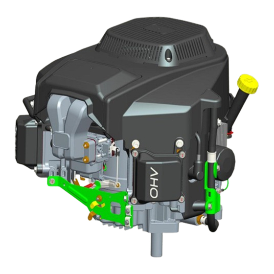
- Page 1 EXMARK V-TWIN AIR COOLED ENGINE SERVICE MANUAL P/N 127-9041 (708cc)
-
Page 2: About This Manual
An electronic version of this service manual is available on the Exmark Dealer Extranet. We are hopeful that you will find this manual a valuable addition to your service shop. If you have any questions or... - Page 3 Maintenance Chapter 1 – General Service Information Chapter 2 - Specifications Chapter 3 - Engine Service and Maintenance Chapter 4 – Engine Disassembly and Service Chapter 5 - Electrical Chapter 1 – General Service Information Safety Safety Precautions Service Rules Engine Model / Serial Number Location Torque Values Engine Specifications...
- Page 4 Maintenance SAFETY PRECAUTIONS WARNING: A hazard that could result in death, serious injury, or substantial property damage. CAUTION: A hazard that could result in minor personal injury or property damage. NOTE: is used to notify people of important installation, operation, or maintenance information. WARNING WARNING CAUTION...
- Page 5 Normal maintenance, replacement or repair of emission control devices and systems may be performed by any repair establishment or individual; however, warranty repairs must be performed by an authorized Exmark dealer. Service Rules 1. Only use genuine Exmark parts and lubrication products.
-
Page 6: Torque Values
Maintenance Serial Number Engine Model 1.1 Torque values Note: For unspecified bolts and nuts listed, refer to the table of standard torque values. Process Description Bolt Specification Torque Range Oil Drain Plug Assy. Oil Drain Plug 20 Ft. Lbs. 26 N.m Spark Plug 21 Ft. - Page 7 17 N.m Oil Filter 9 Ft. Lbs. 12 N.m 1.2 Engine Specifications Standard Service Limit Part Item P/N 127-9041 P/N 127-9041 1800 RPM’s + or – 100 RPM’s Ile speed Engine 3600 RPM’s + or – 50 RPM’s Operating RPM 0.0020”...
- Page 8 Maintenance 0.633” (16.068 mm) Camshaft hole diameter 0.629-0.630” (16-16.018 mm) Crankcase cover 1.578” 40.075 mm) Crankshaft hole diameter 1.575-1.576” (40.009-40.025 mm) - Spark plug 0.0027-0.0031” (0.7-0.8 mm) - Resistance (primary) (1.6-1.9Ω) - Ignition coils Resistance (secondary) (6.27.1kΩ) - Gap to flywheel 0.015-0.016”...
- Page 9 Maintenance Tightening Torque: N·m (ft. lb.) ± 10% 21.7 (16) 27.1 (20) 47.5 (35) 66.4 (49) 81.4 (60) 33.9 (25) 36.6 (27) 47.5 (35) 82.7 (61) 116.6 (86) 139.7 (103) 61.0 (45) 58.3 (43) 76.4 (56) 131.5 (97) 184.4 (136) 219.7 (162) 94.9 (70) Torque Conversions...
- Page 10 Maintenance 2. Specifications 2.1 Specifications--------------------------------------------------2—2 2.2 Dimensional drawings----------------------------------------2—2 2.1 Specifications Model P/N 127-9041 - 708 CC OHV, V-twin –Air Cooled 4-Stroke Type Idle speed 1800 ± 50 rpm 3.03” x 2.99” (77×76mm) Bore X Stroke Displacement(cc) 43.20 Cubic Inches (708 cc) Compression Ratio 8.7 :1...
- Page 11 Maintenance 2-2...
- Page 12 Maintenance 2-3...
- Page 13 Maintenance 2-4...
-
Page 14: Table Of Contents
Maintenance 3 Maintenance 3.1 Maintenance schedule-----------------------------------------3-2 3.2 Engine oil ------------------------------------------------------ 3-2 3.3 Air cleaner ------------------------------------------------------3-3 3.4 Spark plug ------------------------------------------------------3-4 3.5 Valve clearance ------------------------------------------------3-4 3.6 Carburetor ----------------------------------------------------- 3-5 3.7 Governor -----------------------------------------------------3-5 3-1... -
Page 15: Maintenance
Maintenance 3.1 Maintenance Schedule First Every Every Every year Every Each Maintenance schedule month months months or years or 5 hours 25 hours 50 hours hours 200 hours ● Oil level Engine oil ● ● Change ●(1) Air cleaner foam Clean ●(1) element... - Page 16 Maintenance Engine Oil Capacity: 2.1 quarts (2.0 L) Use a high-detergent, premium quality 4-stroke engine oil certified to meet or exceed US. Automobile manufacturers’ requirements for API Service Classification SG, SF. SAE 15W-40 is recommended for general, all-temperature use. Other viscosities shown in the chart may be used when the average temperature in your area is within the indicated range.
-
Page 17: Air Cleaner
Maintenance 3.3 Air Cleaner Lift open door 2. Rotate filter out from rear. CLEANER COVER ELEMENT AIR CLEANER BASE 3. Clean the foam element by squeezing it in warm soapy water, rinsing it, and allowing it to dry. You may also use a nonflammable solvent and then allow it to dry. -
Page 18: Valve Clearance
Maintenance F7RTC BP7RES Recommended types: BOSCH NHSP CHAMPION RN9YC NOTICE Spark plugs of the wrong size or incorrect heat range can cause engine damage. 0.025” – 0.030” 0.70~0.80 mm 1. Disconnect the spark plug lead and remove any dirt from around the spark plug area. 2. -
Page 19: Carburetor
Maintenance 3.6 Carburetor Stop screw Idle speed 1. Start the engine and allow the engine to warm to normal operating temperature. 2. With the engine idling, adjust the throttle stop screw to obtain the recommended engine idle speed. Recommended idle speed: 1800 ± 50 rpm 3.7 Governor 1. - Page 20 Maintenance 4 Disassembly and Service 4.1 Air cleaner --------------------------------------------------4-2 4.2 Engine cover --------------------------------------------------4-3 4.3 Control lever -------------------------------------------------4-4 4.4 Air Intake -----------------------------------------------------4-5 4.5 Carburetor ----------------------------------------------------4-5 4.6 Ignition coil --------------------------------------------------4-6 4.7 Flywheel/breather--------------------------------------------4-7 4.8 Cylinder head & valves -------------------------------------4-8 4.9 Crankcase cover/ governor --------------------------------4-11 4.10 Crankshaft /piston / camshaft ---------------------------4-14 4-1...
-
Page 21: Air Cleaner
Maintenance 4.1 Air Cleaner 4-2... -
Page 22: Engine Cover
Maintenance 4.2 Engine Cover 4-3... -
Page 23: Control Lever
Maintenance 4.3 Control Lever Removal / Installation 4-4... -
Page 24: Air Intake
Maintenance 4.4 Air Intake 4-5... -
Page 25: Carburetor
Maintenance 4.5 Carburetor NOTICE Torque Range Process Description Bolt Specification In.lb. Solenoid Valve 53.1~79.6 Fuel Cup Screw M4 1.5~2.0 13.3~17.7 Fuel Plug Flange Bolt M6 53.1~79.6 Pin,Float Screw M3 1.8~3.0 15.9~26.5 Main Jet 1.2~1.7 10.6~15 4-6... -
Page 26: Ignition Coil
Maintenance 4.6 Ignition Coil Igniting coil gap adjustment When reinstalling ignition coils, adjust the air gap to: (0.015” – 0.020”) 1) Lightly tighten the igniting coil mounting bolt. 2) Insert the feeler gauge or a piece of paper of the same thickness between the flywheel and coil as shown. -
Page 27: Flywheel/Breather
Maintenance 4.7 Flywheel /Breather Removal / installation NOTICE: Disassembly: Do not hit the flywheel with a hammer. Remove with a commercially available puller. Avoid the magnet section when attaching the puller. Reassembly: Make certain there are no metal objects stuck to the magnet. Adjust the ignition coil air gap after reassembly. -
Page 28: Cylinder Head & Valves
Maintenance 4.8 Cylinder Head & Valves Removal / Installation: Remove the following: 1. engine cover 2. carburetor 3. Shroud Comp Cylinder Head-Right 4-9... - Page 29 Maintenance Cylinder Head-Left NOTICE: Removal /Installation Loosen and tighten Bolt, Cylinder Head in a crisscross pattern in 2~3 steps; Before installation, remove any carbon deposits from the combustion chamber and inspect the valve seats; Measure the cylinder compression after reassembly. 4-10...
- Page 30 Maintenance Disassembly / Reassembly Inspection Cylinder Head-Right 4-11...
- Page 31 Maintenance Cylinder Head-Left Valve Spring Free Length Measure the free length of the valve springs. Standard Service limit 1.55” – 1.60” 1.53” Replace the spring if they shorter than the service limit. Valve Seat Width Remove carbon deposits from the combustion chamber.
- Page 32 Maintenance Cylinder Head STRAIGHT EDGE 1、Remove carbon deposits from the combustion chamber. Clean off any gasket material from the cylinder head surface. 2、Check the spark plug hole and valve areas for cracks. 3、Check the cylinder head for warpage with a straight edge and a feeler gauge as shown.
- Page 33 Maintenance Exhaust Valve Guide Reaming For best results, be sure the cylinder head is at room temperature before reaming the exhaust valve guide. 1. Coat the reamer and valve guide with cutting oil. VALVE GUIDE 2. Rotate the reamer clockwise through the valve REAMER 0.259”...
- Page 34 Maintenance Valve Seat Width Standard Service limit 0.0275” – 0.0315” 0.050” 1. Make a light pass with the 45° cutter to remove any possible burrs at the edges of the seat. 2. After resurfacing the seats, inspection for even valve seating. 3.
- Page 35 Maintenance 4.9 Crankcase Cover / Governor Disassembly / Reassembly Governor NOTICE: Check that the governor moves smoothly. 4-16...
- Page 36 Maintenance Crankcase cover 4-17...
- Page 37 Maintenance 4.10 Crankshaft / Piston / Camshaft Remove /installation 4-18...
-
Page 38: Piston Connecting Rod
Maintenance Disassembly / Reassembly Piston connecting rod Assembly: Sign . Put the piston ring sign facing up when assembling. . Don’t wrongly assemble the top ring and the second ring. . After assembling, be sure the piston can freely move. Top ring . - Page 39 Maintenance Piston Pin OD Model Standard Service limit 0.6689” – 0.6692” 0.6653” LC2P77F 4-20...
- Page 40 Maintenance Cylinder Inside Diameter Measure three points on the “X” and “Y” shaft and record cylinder inside diameter(“X” shaft is vertical to crankshaft and “Y” shaft parallel to crankshaft). Take maximum reading as the wearing and tapering of the cylinder. Model Standard Service limit...
- Page 41 Maintenance Piston Ring End Gap Standard Service limit 0.0078” – 0.0157” 0.0177” Before measuring end gap, use the piston top to position the ring so it will not be cocked in the cylinder bore. Connecting Rod Small End ID Model Standard Service limit 0.6695”...
- Page 42 Maintenance Connecting Rod Large End Axial Clearance Standard Service limit 0.0177” – 0.0374” 0.0413” Connecting Rod Large End Oil Clearance(Radial) 1) Clean all oil from the crankshaft neck journal and inside side. 12.5 N·m 2) Place a piece of plastic gauge on the crankshaft neck journal, assemble connecting rod, and tighten the bolts to specified torque.
- Page 43 Maintenance Chapter 5 – Electrical System Information Ignition Coil Gap Adjustment Ignition Coil Resistance Inspection Spark Testing Fuel Solenoid Charging System Specifications AC Output Test DC Output Test 4-24...
-
Page 44: Ignition Coil Gap Adjustment
Maintenance Ignition Coil Gap Adjustment High Voltage Ignition Systems can be Dangerous - Use Caution when Servicing Ignition Systems 4) Install the ignition coil and lightly tighten the ignition coil mounting bolts. 5) Rotate engine so ignition coil is aligned with the magnet portion of the flywheel. 6) Insert the feeler gauge between the flywheel and coil. -
Page 45: Spark Testing
Maintenance Spark Testing - Fuel is Extremely Flammable - Use Extreme Caution When Servicing the Fuel System - High Voltage Ignition Systems can be Dangerous - Use Caution when Servicing Ignition Systems 1. Remove spark plug cap from the spark plug. 2. -
Page 46: Charging System Specifications
Maintenance Charging System Specifications Charge Coil(s) Air Gap 0.011- 0.019” (.3-.5 mm) Measure Between the Magnet Area of the Flywheel and the Charge Coil Legs No Load DC Voltage Output @ 3000 RPM 14.5 +/- .5 Volts DC Measure Across Battery Terminals No Load AC Voltage Output @ 3000 RPM 30 VAC Measure Across Stator Leads –... -
Page 47: Dc Output Test
Maintenance DC Output Test Insert RED test lead into 1 receptacle in meter. Insert BLACK test lead into COM receptacle in meter. Rotate selector to A== (DC AMPS) position. Attach RED test lead clip (1) DC output pin (6)in connector (4), Fig.16. If NO or LOW output is found, replace stator.