Table of Contents
Advertisement
Advertisement
Table of Contents

Related Manuals for Woods RD6000


Summary of Contents for Woods RD6000
- Page 1 REARMOUNT RD6000 RD7200 RD8400 OPERATOR’S MANUAL PN-52886 (Rev. 8/23/01)
- Page 2 Dealer Check List items have been completed. The dealer is to return the prepaid postage portion to Woods, give one copy to the customer, and retain one copy. Note: Warranty credit is subject to this form being completed and returned.
- Page 3 ........Inside Back Cover RD6000, RD7200 & RD8400 SPECIFICATIONS...
-
Page 4: General Information
GENERAL INFORMATION The purpose of this manual is to assist you in change the machines as may be necessary without operating and maintaining your mower. Read it notification. carefully. It furnishes information and instructions that will help you achieve years of dependable perform- WARNING ance. -
Page 5: Bolt Torque Chart
BOLT TORQUE CHART Always tighten hardware to these values unless a different torque value or tightening procedure is listed for a specific application. Fasteners must always be replaced with the same grade as specified in the manual parts list. Always use the proper tool for tightening hardware: SAE for SAE hardware and Metric for metric hardware. Make sure fastener threads are clean and you start thread engagement properly. -
Page 6: Safety Rules
SAFETY RULES ATTENTION! BECOME ALERT! YOUR SAFETY IS INVOLVED! ! Before starting tractor, check all equipment Safety is a primary concern in the design and driveline guards for damage and make sure they ro- manufacture of our products. Unfortunately, our tate freely on all drivelines. - Page 7 SAFETY RULES ATTENTION! BECOME ALERT! YOUR SAFETY IS INVOLVED! ! Do not operate equipment while under the components to the ground, operate valve levers to release any hydraulic pressure, set parking brake, influence of alcohol or drugs. stop engine, remove key, and unfasten seat belt. ! Operate only in daylight or good artificial light.
- Page 8 SAFETY RULES ATTENTION! BECOME ALERT! YOUR SAFETY IS INVOLVED! (Safety Rules continued from previous page) ! Wear gloves when installing belt. Be careful to prevent fingers from being caught between belt ! Tighten all bolts, nuts and screws to torque and pulley.
-
Page 9: Safety Decals
SAFETY DECALS ATTENTION! BECOME ALERT! YOUR SAFETY IS INVOLVED! Replace Immediately If Damaged! DANGER MODEL NO. SERIAL NO. YR OF MFG. ID NO. MASS (KG) OREGON, IL U.S.A. 3 - - Serial Number Plate ROTATING BLADES AND THROWN OBJECTS DANGER "... - Page 10 SAFETY DECALS ATTENTION! BECOME ALERT! YOUR SAFETY IS INVOLVED! Replace Immediately If Damaged! (Safety Decals continued from previous page) DANGER GUARD MISSING. DO NOT OPERATE. DANGER 4 - - Part #53597 5 - - Part #18866 GUARD MISSING. WARNING DO NOT OPERATE. 33347E PTO speeds higher than 540 RPM can cause DANGER...
- Page 11 OPERATION CAUTION Safety is a primary concern in the design and manufacture of our products. Unfortunately, our ! Stop tractor and implement immediate- efforts to provide safe equipment can be wiped ly upon striking an obstruction. Turn off out by an operator’s single careless act. engine, remove key, inspect and repair any damage before resuming operation.
-
Page 12: Cutting Height Adjustment
Top Link Attachment (Figure 2) WARNING When the cutting height is adjusted, adjust tractor top ! Keep all persons away from operator link until mower top link attachment point “A” is control area while performing adjust- aligned vertically with mower hitch pin “B.” ments, service or maintenance. - Page 13 Front Caster Arm Configuration for RD6000 & RD7200 Only (Figure 5) The RD6000 and RD7200 front casters can be set in two positions. This is accomplished using right and left offset caster arms. The figure shows a right offset assembly. The direction of the offset is defined by looking from the mounting hole “A”...
- Page 14 Front Roller (Optional) Should mower become plugged, causing belt to slip for over two seconds, maneuver equipment into a The caster wheels and side skids effectively reduce previously cut area and allow mower to clear scalping in most cases. However, you may encounter accumulated material.
- Page 15 Uneven Terrain Collapse driveshaft as far as possible and store it in PTO hanger bracket to prevent ground contact. Place WARNING blocks under mower side skids. Lower mower onto blocks, disconnect mower from tractor 3-point hitch, ! Do not operate on steep slopes. and carefully drive tractor away from mower.
-
Page 16: Owner Service
OWNER SERVICE BLOCKING METHOD Safety is a primary concern in the design and (Figure 8) manufacture of our products. Unfortunately, our efforts to provide safe equipment can be wiped Do not work underneath mower unless it is properly out by an operator’s single careless act. attached to the tractor and blocked securely. - Page 17 Use a lithium grease of #2 consistency with a MOLY Overfilling the gearbox will cause the excess gear (molybdenum disulfide) additive for all locations. Be lube to blow out vent plug. The gear lube could then sure to clean fittings thoroughly before attaching ruin the belt.
- Page 18 Inspect blades for condition and proper installation each time before operation. Replace any blade that is bent, excessively nicked, worn or has any other damage. Figure 11. Blade Installation for Small nicks can be ground out when sharpening. RD6000 SN 793923 and prior (Rev. 6/28/01) PN-52886 (4/97)
- Page 19 RD6000 (SN 793924 and after) RD7200 and RD8400 (Figure 12) RD7200 and RD8400 (Figure 12) Place cap screws (3) through outer holes in blade and Remove cap screws (3) and nuts (4). spindle shaft. Make sure blade cutting edge is positioned to lead in clockwise rotation, as viewed from top of mower.
-
Page 20: Dealer Service
DEALER SERVICE The information in this section is written for dealer Raise mower completely, set tractor brakes, turn service personnel. The repair described herein engine off, remove key, block tractor wheels front and requires special skills and tools. If your shop is not rear, and disconnect mower driveline from tractor. - Page 21 3. Sleeve 4. Bearing cone 5. Bearing cup 6. Spindle housing SEAL LIP 7. Spindle shaft RD6000 RD6000 after SN 793923 SN 793923 and prior RD7200 & RD8400 CD5061 CD4107 Figure 15. Blade Spindle Assemblies Spindle Assembly Install top bearing on shaft to mate with top cone.
- Page 22 Identify the open side of the seal containing the Install top bearing on shaft to mate with top cone. spring. Apply a thin coat of Permatex to shaft area where Lightly coat, with Permatex, the area of housing sleeve will seat. where seals seat.
- Page 23 Leakage Repair Recommended sealant for gearbox repair is Perma- tex Aviation 3D Form-A-Gasket or equivalent. Leakage can occur at the vertical or horizontal gaskets and shaft seals. Leakage at the horizontal gasket or seal can be repaired without removing the gearbox from the cutter.
- Page 24 Remove input shaft (3) with bearing (8) from front Insert input bearing (9) in the housing using a round cover (6). Remove bearing (8) from input shaft (3). tube of correct diameter using a hand press. Remove input bearing (9) by using a punch and Press gear (1) on input shaft (3) making sure hammer from outside the housing.
- Page 25 1. Bevel gear 2. Gearbox housing 3. Keyed gear shaft 4. 12T Pinion shaft 5. Spacer 6. Gearbox cover 17. Internal retaining ring 125mm 7. Washer, 1.58 x 3.13 x .04 18. 3/8 NPT Square head pipe plug 8. Ball bearing 6007 19.
- Page 26 UNIVERSAL JOINT REPAIR Clamp cup in vise as shown in Figure 23 and tap on yoke to completely remove cup from yoke. Repeat steps two and three for opposite cup. 1. Yoke 2. Cup and bearings 3. Snap ring 4. Journal cross CD1645A Figure 20.
- Page 27 U-Joint Assembly tension. Repeat until both yokes move in all directions without restriction. Place seals securely on bearing cups. Insert cup into yoke from outside and press in with hand pressure as far as possible. Insert journal cross into bearing cup with grease fitting away from shaft.
-
Page 28: Trouble Shooting
TROUBLE SHOOTING MOWING CONDITIONS PROBLEM POSSIBLE CAUSE SOLUTION Grass cut higher in center of Height of mower higher at front Adjust mower height and atti- swath than at edge than at rear tude so that mower rear and front are within 1/2” of same height. - Page 29 TROUBLE SHOOTING BELT CONDITIONS PROBLEM POSSIBLE CAUSE SOLUTION Belt slippage Mower overloading; material too Reduce tractor ground speed but tall or heavy maintain full PTO rpm. Cut material twice, one high pass and then mow at desired height. Cut a partial swath.
-
Page 30: Assembly Instructions
Assembly of the mower is the responsibility of the customer and all operators read it before operat- WOODS dealer. It should be delivered to the owner ing equipment. Point out the manual safety rules, completely assembled, lubricated and adjusted for explain their meanings and emphasize the in- normal conditions. - Page 31 ASSEMBLY PROCEDURE Loosen 5/8” nut at lower hitch point and install offset link as shown. Tighten nut securely. Repeat for opposite side. Note that front link with the PTO storage Uncrating Mower bracket should be installed on right side of mower as (Figure 26) shown in Figure 27.
- Page 32 Rear Caster Wheel Installation The counter-cone drive shield is factory installed on (Figure 30) models RD6000 and RD7200. On the RD8400 model, attach counter-cone shield (5) CASTER WHEEL ASSEMBLY to gearbox (9) with cap screws (3) and flat washers (4). Orient chain attachment lug as shown.
- Page 33 Optional Front Roller Installation Put roller bracket (2) over bolts then install flange locknuts (5) on bolts and tighten. (Figure 33) Put front roller (1) in roller bracket and insert roller pin (4) through bracket and roller. Install retainer pin (3) in roller pin. Put cap screw (6) through bracket and retainer pin, install flange locknut (5) and tighten.
- Page 34 NOTES PN-52886 (4/97)
- Page 35 ......BLADE & SPINDLE ASSEMBLY RD6000 (SN 793932 and prior) & RD7200 (SN--688690 and prior) . . .
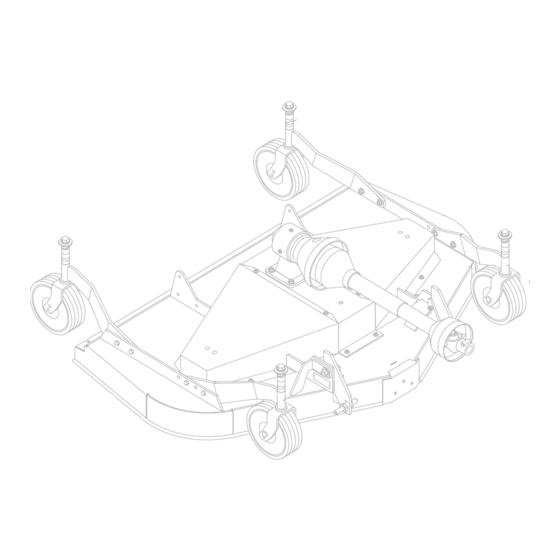
- Page 36 RD6000, RD7200 & RD8400 MAIN FRAME ASSEMBLY 27 -- COMPLETE DECAL SET 28 -- FRENCH SAFETY DECAL SET 29 -- ENGLISH SAFETY DECAL SET 20 24 68 67 CD4986A Part Part Used Description Used Description 52860 RD8400 Caster shaft and yoke...
- Page 37 8mm x 1.25P x 16mm Hex head cap 38 & 39) screw GR8.8 10 31615 V-Belt (used on RD6000 only) - -or- - 44 62153 Whiz bolt, .375--16 x 1 flanged 10 18879 V-Belt (used on RD7200 only) - -or- -...
- Page 38 RD6000, RD7200 & RD8400 GEARBOX ASSEMBLY Part Used Description 53593 1:1.92 Gearbox with decal 51949 1.38 x 4.5 x 23T Bevel gear ---------- Gearbox housing (not sold sepa- rately) 51945 .887 Input shaft 51944 3.0 x 12T Pinion shaft 20886 2.76 x 3.00 x 3.3 Spacer...
- Page 39 RD6000, RD7200 & RD8400 DRIVE SHAFT - - MALE HALF COMER (TRI- -LOBE SHAFT) Part Used Description 51848 Drive, Profile shield 40, 26.2, 1.38 SP 30912 Yoke 40, 1.38 QD (includes item #11) 30916 U-Joint repair kit 40 30928 Yoke and tube, Profile 40 x 26.2...
- Page 40 53584 .641 x 3 Bellville washer 986* 5/8 NC x 2-3/4 Hex head cap screw HT (RD7200) - -or- - 23141 5/8 NC x 3-1/2 Hex head cap scrrew HT (RD6000) 4358 1/2 NF x 1-1/4 Hex head cap screw GR5 51760 Spindle wrench...
- Page 41 BLADE & SPINDLE ASSEMBLY: RD6000 (SN- -793924 AND AFTER) RD7200 (SN- -688691 AND AFTER) & RD8400 (ALL) Part Description 37009 7/8--18 UNF Hex jam nut 10378 1/4 NC x 1 Hex head cap screw GR5 52898 .929 x 1.41 Lockwasher 1985 1/4 Standard lockwasher 34440 H 1”...
- Page 42 RD6000- -RD7200- -RD8400 DRIVESHAFT WALTERSCHEID (TWO-LOBE SHAFT) (SN- -718454 AND AFTER) CD5556 TWO TYPES OF DRIVESHAFTS HAVE BEEN USED FOR RD MOWERS - - - - TRI-LOBE AND TWO-LOBE. CHECK YOUR DRIVESHAFT AND ORDER REPAIR PARTS FROM THE CORRESPONDING PARTS LIST.
- Page 43 Removing Mower from Tractor, 13 Top Link Attachment, 10 Tractor Stability, 9 DEALER SERVICE Tractor Top Link Adjustment, 11 Blade Spindle Assembly OWNER SERVICE RD6000 & RD7200, 19 Belt Replacement, 16 RD8400, 20 Blade Servicing, 16 Disassembly, 18 Installation Installation, 20 RD6000, 17 Removal, 18 RD7200 &...
- Page 45 PART NUMBER 52886 Woods Equipment Company 2606 Illinois Route 2 South Post Office Box 1000 Oregon, Illinois 61061 815-732-2141 tel 815-732-7580 fax $ 1997 Woods Equipment Company. All rights reserved.