
Related Manuals for Raymarine stand-alone master instrument


Summary of Contents for Raymarine stand-alone master instrument
- Page 1 Distributed by Any reference to Raytheon or RTN in this manual should be interpreted as Raymarine. The names Raytheon and RTN are owned by the Raytheon Company.
- Page 2 TOP EDGE BLEED MASK FOR 2 COLOUR SEATALK LOGO ST 30 BIDATA Operation and Installation...
- Page 3 TOP EDGE BLEED MASK FOR 2 COLOUR SEATALK LOGO Nautech Limited, Anchorage Park, Portsmouth P03 5TD, England Telephone (0705) 693611. Fax (0705) 694642...
- Page 4 ST30 Bidata Operation and Installation Handbook Autohelm and SeaTalk are registered Trade Marks of Nautech Limited Autohelms policy of continuous improvement and updating may change product specifications without prior notice Copyright Nautech 1992 o t s B I D D681...
-
Page 5: Package Contents
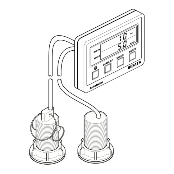
Package Contents The following items are included in the ST30 Bidata package: ST30 Bidata instrument Fixing studs (2 off) Thumb nuts (2 off) Mounting template 1m power cable Depth transducer (through hull) with 10m cable and 1/8in spade connectors Speed transducer (through hull) with 10m cable and 1/8in spade connectors (0 to 32 knots) Instrument cover Operation and installation handbook... -
Page 6: Table Of Contents
Contents Introduction ... 5 Chapter 1: Control Head Installation ... 7 Chapter 2: Transducer Installation ... 11 Chapter 3: Fault Finding ... 18 Chapter 4: Maintenance ... 20 Operation Chapter 5: Operation ... 21 Chapter 6: Calibration ... 25 1.1 Siting ... 7 1.2 Mounting procedure ... - Page 7 Contents (cont.) Chapter 7: Specification ... 39 6.2 Speed calibration ... 31 Units selection Ð speed ... 31 Units selection Ð log ... 32 Exit calibration ... 32 Log calibration ... 33 Enter correction factor (CF) ... 34 6.3 Calibration Lock/Unlock ... 35 6.4 Master/Repeater mode ...
-
Page 8: Introduction
ST30 Bidata Operation and Installation Handbook Introduction Designed for above or below deck installation, the ST30 Bidata can be used as a stand-alone master instrument or set to repeat depth and speed information from the SeaTalk bus. The ST30 Bidata will display the following information: •... - Page 9 ST30 Bidata Operation and Installation Handbook...
-
Page 10: Chapter 1: Control Head Installation
Chapter 1: Control Head Installation Chapter 1: Control Head Installation 1.1 Siting The ST30 Bidata instrument may be installed above or below deck where it is: • easily read by the helmsman (normally viewed at eye level) • protected from physical damage •... -
Page 11: Mounting Procedure
1.2 Mounting procedure 1 Instrument 2 Fixing studs 3 Thumb nuts 4 Sealing gasket 5 Depth transducer cable 6 Speed transducer cable ST30 Bidata Operation and Installation Handbook Make sure the surface to which the instrument (1) is to be mounted is smooth and flat. -
Page 12: Power Supply (Stand-Alone Operation)
Chapter 1: Control Head Installation 1.3 Power supply (Stand-alone operation) Caution: The ST30 Bidata must be connected to a 12V supply only. For stand-alone operation, use the standard 1m cable supplied. 1.4 Power supply (SeaTalk system) The ST30 Bidata can be connected to an existing SeaTalk system using a Standard SeaTalk Extension or Interface Cable. -
Page 13: Connection To Adjacent St30 Instruments
1.5 Connection to adjacent ST30 Instruments The ST30 Bidata is supplied with a daisy-chain cable that allows adjacent ST30 instruments to be linked together. The daisy-chain cable supplies power to adjacent instruments and allows data to be transmitted and received via the SeaTalk bus. The daisy-chain cable plugs into one of the SeaTalk ports on the back cover. -
Page 14: Chapter 2: Transducer Installation
Chapter 2: Transducer Installation Chapter 2: Transducer Installation 2.1 Connection to instrument The depth and speed transducers are supplied with 10m (32.5ft) of cable. These cables are fitted with female spade connectors that plug directly into the back of the ST30 Bidata instrument. 2.2 Transducer type The ST30 Bidata system is supplied (as standard) with plastic through hull transducers. -
Page 15: Depth
Depth Hull material or location GRP, Steel, Aluminium Standard through hull Wood GRP, Steel, Aluminium Retractable depth (Z120) In hull Speed Hull material or location GRP, Steel, Aluminium Up to GRP, Steel, Aluminium Up to Wood Transom Speed and depth Hull material or location Transom... -
Page 16: Paddlewheel Replacement
Chapter 2: Transducer Installation 2.3 Paddlewheel replacement If the high speed paddlewheel (supplied) is to be fitted, or the existing paddlewheel to be replaced, proceed as follows: Remove the retaining rings (1) and pin (6) from the speed transducer (3). Withdraw the speed transducer (3) from the through hull fitting (4). -
Page 17: Installation
2.4 Installation The depth and speed transducers are supplied with detailed installation and maintenance instructions. These instructions, together with following notes, should be read thoroughly before attempting to install the transducers. Speed transducer (through hull) For accurate speed readings, locate the speed transducer in the shaded ''clear flow' areas as shown. -
Page 18: Siting Of Depth Transducer (Standard Through Hull)
Chapter 2: Transducer Installation Siting of depth transducer (Standard through hull) The depth transducer must be vertical to within 10°, forward, aft and athwart ships. 2.5 Cabling Run the transducer cable back to the instrument. Avoid fluorescent lights, engines, radio transmitting equipment and, in the case of the depth transducer, avoid the speed transducer cable. - Page 19 If any of the following transducers are to be used; • Bronze through hull depth (Z118) • In hull puck (Z117) • Retractable depth (Z120) • Bronze through hull speed (Z116) • Transom mount speed (Z119) • Bronze through hull triducer (Z093) •...
- Page 20 Chapter 2: Transducer Installation Transducer type Bronze through hull triducer (Z093) Biducer (Z183) Colour coding (cable to unit) Brown & white Ð cut back Red Ð red speed terminal Screen Ð white speed terminal Green Ð green speed terminal Blue Ð red depth terminal Black &...
-
Page 21: Chapter 3: Fault Finding
Chapter 3: Fault Finding All Autohelm products are, prior to packing and shipping, subject to comprehensive test and quality assurance programmes. However, in the unlikely event that a fault does occur with the ST30 Bidata, the following table will help to identify the probable cause and provide the most likely cure. - Page 22 Chapter 3: Fault Finding Fault Failure of a group of instruments in a chain Unable to enter calibration Note: After installation, poor performance may be experienced if the surface of the depth transducer has not been 'wetted'. Wetting can take up to 24 hours under normal conditions.
-
Page 23: Chapter 4: Maintenance
Chapter 4: Maintenance 4.1 Instrument Atmospheric conditions may cause condensation to appear on the instrument window. This will not harm the instrument and can be cleared by increasing the illumination setting to level 3. Chemical and abrasive materials must not be used to clean the ST30 Bidata instrument;... -
Page 24: Chapter 5: Operation
Chapter 5: Operation Chapter 5: Operation The ST30 Bidata is set in the factory to: • display depth in feet • display speed in knots • operate with the depth alarms switched off • operate in Master mode These settings can be changed in calibration (section 6.1). When the ST30 Bidata is switched on, depth information (upper display) and speed information (lower display) is shown in the units set up in calibration. -
Page 25: Speed Key
• Deep alarm DEPTH SPEED • Minimum depth DEPTH SPEED • Offset Keel/Waterline DEPTH SPEED A further press of Depth will return the unit to current Depth. The above menu will automatically return to current Depth after 8 seconds if there are no further key commands. - Page 26 Chapter 5: Operation • Log DEPTH SPEED • Maximum Speed DEPTH SPEED • Average Speed DEPTH SPEED A further press of Speed will return the unit to current boat speed. Note: Log distances over 999nm or miles are displayed in thousands, hundreds and tens (e.g., 1th 510nm).
-
Page 27: Light Key
5.3 Light Key Cycles the level of instrument illumination. There are 3 levels with level 3 the brightest. The display returns to current speed after 8 seconds or when speed key is pressed. Note: When the ST30 Bidata is used in a SeaTalk system, illumination may be adjusted from any instrument. -
Page 28: Chapter 6: Calibration
Chapter 6: Calibration Chapter 6: Calibration 6.1 Depth calibration The ST30 Bidata can be programmed to display depth information in feet or metres, set alarms for shallow and deep water and allow for keel or waterline offsets. To select the calibration menu, press and hold seconds the display will show CAL. -
Page 29: Units Selection Ð Depth
Units selection – depth Shallow alarm ST30 Bidata Operation and Installation Handbook Cycle Depth until the display shows feet or metres. DEPTH SPEED DEPTH SPEED Select feet or metres, as required, using Reset. DEPTH SPEED DEPTH SPEED Cycle Depth until the 'Shallow' alarm is displayed. DEPTH Shallow SPEED... -
Page 30: Deep Alarm
Chapter 6: Calibration Deep alarm Press Reset or to set the required depth. DEPTH Shallow SPEED DEPTH SPEED The Shallow Alarm is enabled by pressing Speed. When the alarm is on the 'Alarm' legend is displayed. DEPTH Alarm Shallow SPEED DEPTH SPEED Cycle Depth until 'Deep' alarm is displayed. - Page 31 ST30 Bidata Operation and Installation Handbook Press Reset or to set the required depth. Deep DEPTH SPEED DEPTH SPEED The 'Deep' alarm is enabled by pressing Speed. When the alarm is on the 'Alarm' legend is displayed. Deep DEPTH Alarm SPEED DEPTH SPEED...
-
Page 32: Offset
Chapter 6: Calibration Offset The instrument measures the water depth below the transducer. To display water depth below the keel or to the surface an offset must be set up. A negative offset is used to reduce the displayed value to give water depth below the keel. -
Page 33: Exit Depth Calibration
Exit depth calibration To exit depth calibration and return to depth mode, press and hold Depth for 2 seconds. ST30 Bidata Operation and Installation Handbook Press Depth until 'Offset' is selected. Offset DEPTH SPEED DEPTH SPEED Press Reset or until the required offset is displayed. Offset DEPTH SPEED... -
Page 34: Speed Calibration
Chapter 6: Calibration 6.2 Speed calibration The ST30 Bidata can be set to display speed in knots or mph and trip and total distance in nm or miles. The most important speed calibration feature is Log Calibration; this calibrates the transducer paddlewheel to the vessel's hull so that accurate speed/log related information is displayed. -
Page 35: Units Selection Ð Log
Units selection – log Exit calibration Press and hold ST30 Bidata Operation and Installation Handbook Cycle Speed until the display shows nm or miles. DEPTH SPEED DEPTH SPEED Press Reset to select nm or miles. DEPTH SPEED DEPTH SPEED and Depth for 2 seconds. DEPTH SPEED DEPTH... -
Page 36: Log Calibration
Chapter 6: Calibration Log calibration The ST30 Bidata should not be used for navigational purposes until the transducer paddlewheel has been calibrated to suit the characteristics of the vessel. This is a simple operation and is carried out as follows: Choose two charted points that are approximately 1nm apart. -
Page 37: Enter Correction Factor (Cf)
Enter correction factor (CF) ST30 Bidata Operation and Installation Handbook Press and hold and Depth. After 2 seconds the display will show CAL. DEPTH SPEED DEPTH SPEED Press Speed 3 times to select 'Log Calibration'. DEPTH SPEED DEPTH SPEED Set the calculated correction factor (CF) using Reset or DEPTH SPEED DEPTH... -
Page 38: Calibration Lock/Unlock
Chapter 6: Calibration 6.3 Calibration Lock/Unlock The lock/unlock feature removes the risk of accidentally changing the calibration values set for log calibration, shallow alarm etc. For security, the calibration lock/unlock feature is accessed by an extended hold down of To exit calibration and return to 'Speed and Depth' mode, press and hold and Depth for 2 seconds. - Page 39 C0 = Calibration Locked, i.e. no access C1 = Calibration Unlocked, i.e. normal access ST30 Bidata Operation and Installation Handbook Press Speed and Reset momentarily DEPTH SPEED DEPTH SPEED Calibration Lock/Unlock is switched on or off using Reset. DEPTH SPEED DEPTH SPEED To exit 'Calibration Lock/Unlock', press and hold...
-
Page 40: Master/Repeater Mode
Chapter 6: Calibration 6.4 Master/Repeater mode As it leaves the factory, the ST30 Bidata is set to operate in master mode. In this mode the instrument is connected to speed and depth transducers, and transmits data onto the SeaTalk Bus. The Bidata can be set as a repeater, to repeat depth and speed information already on the SeaTalk bus. - Page 41 Note: When the Bidata is set to Repeater mode access to calibration is inhibited. ST30 Bidata Operation and Installation Handbook Press Reset to change between modes DEPTH SPEED DEPTH SPEED To exit calibration, press and hold DEPTH SPEED DEPTH SPEED RESET BIDATA and Depth for 2 seconds.
-
Page 42: Chapter 7: Specification
Chapter 7: Specification Chapter 7: Specification Detailed Specification: Power Consumption: Depth transmitted power: Receiver sensitivity: Depth operating frequency: Voltage range: Operating temperature: Calibration lock/unlock: Illumination: Repeater capability: Depth: Depth: Shallow alarm: Deep alarm: Offset: Minimum depth: Units: 60mA (normal) 100mA (illuminated) 0.5mV 200kHz 10 to 16V... - Page 43 Speed: Boat speed: Trip distance: Log (non resetable): Average speed: Maximum speed: Units: Manual log calibration: ST30 Bidata Operation and Installation Handbook 0 to 99.9 knots or mph (0.1 increments) 0 to 999nm or miles (0.01 increments to 9.99, 0.1 to 99.9 and 1.0 to 999). 0 to 5999nm or miles (0.1 increments to 99.9 and 1.0 to 5999).
- Page 44 TOP EDGE BLEED MASK FOR 2 COLOUR SEATALK LOGO Nautech Limited, Anchorage Park, Portsmouth P03 5TD, England Telephone (0705) 693611. Fax (0705) 694642...
- Page 45 TOP EDGE BLEED MASK FOR 2 COLOUR SEATALK LOGO Nautech Limited, Anchorage Park, Portsmouth P03 5TD, England Telephone (0705) 693611. Fax (0705) 694642...