Table of Contents
Advertisement
Available languages
Available languages
Quick Links
Advertisement
Chapters
Table of Contents

Related Manuals for RIDGID DMG9015


Summary of Contents for RIDGID DMG9015
- Page 1 OPERATOR’S MANUAL UNIVERSAL DIGITAL MITER GAUGE DMG9015 WARNING: To reduce the risk of injury, the user must read and understand the operator’s manual before using this product. Thank you for buying a RIDGID product. SAVE THIS MANUAL FOR FUTURE REFERENCE...
-
Page 2: Table Of Contents
TABLE OF CONTENTS n General Safety Instructions ............... . 3 Safety Symbols . -
Page 3: General Safety Instructions
GENERAL SAFETY INSTRUCTIONS The purpose of safety symbols is to attract your attention to WARNING: possible dangers. The safety symbols and the explanations Always keep the miter fence away from the blade with them deserve your careful attention and understanding. when guiding the workpiece with this digital miter The symbol warnings DO NOT, by themselves, eliminate gauge. -
Page 4: Unpacking And Checking Contents
Separate all the parts from the packing materials. Refer to the”List of Contents” and Fig. 1 to make certain that all the items are accounted for before discarding any packing ma- terial. Call the RIDGID Service Center if any parts are dam- aged or missing. List of Loose Parts... -
Page 5: Getting To Know Your Digital Miter Gauge
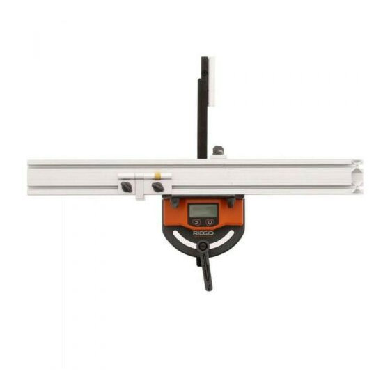
GETTING TO KNOW YOUR DIGITAL MITER GAUGE The digital miter gauge is a smart tool that increases efficiency in woodworking projects. It was designed by a professional woodworker for woodworkers. It sets crosscut angles and table saw blade angles from -50° to +50° with ±0.1° accuracy in a matter of seconds. -
Page 6: Technical Specifications
GETTING TO KNOW YOUR DIGITAL MITER GAUGE Technical Specifications 1. Machined Miter Gauge head 2. Power button: press to turn on the digital miter gauge; Battery 2 “AAA” 1.5V batteries press again to flip the display; Miter angle range -50° to +50° 3. -
Page 7: Operation
OPERATION TO INSTALL BATTERIES ATTACH THE FENCE TO THE MITER GAUGE HEAD This digital miter gauge uses two ”AAA” batteries. The fence has a mitered end to permit precise miter cuts close to the end of the miter fence. Always position this end to right side of the miter head. -
Page 8: Choose The Proper Gauge Bar Attachment
OPERATION CHOOSE THE PROPER GAUGE BAR ATTACH- The 3/8” T-slot washer (Fig. 7a) is attached to the front side MENT of the gauge bar (Fig. 8). Use this washer for T-slots that are 3/8” deep. For T-slots that are ½” deep, remove the 1/8”... -
Page 9: Turn The Digital Miter Gauge On And Off
OPERATION CALIBRATE THE DIGITAL MITER GAUGE TO THE TABLE-SAW BLADE ASSEMBLY (Carpenter’s square, available separately, required) NOTE: • A lways calibrate the digital miter gauge to your table saw before using this miter gauge to guide a cut. Failure to perform the calibration may result in an inaccurate cut- ting. -
Page 10: Application
APPLICATION USE THE PRECISION FENCE ACCESSORIES CUT WOOD AT ANY ANGLE WITH ±0.1º AC- CURACY This digital miter gauge offers a variety of precision fence accessories which will allow the user to fully utilize the miter WARNING: gauge capabilities. Always keep the miter fence away from the blade when guiding the cut with this digital miter gauge. -
Page 11: Set The Table-Saw-Blade Tilt Angle
APPLICATION Orient the magnets to the correct side 45,0° Fig.18 1. Use the 1/8-in. hex wrench (included) to loosen the set- Micro-adjust screw screw in the magnetic blade attachment in the counter- Fig.17 clockwise direction. The Micro-adjust Gauge is designed to be used in any of the 2. - Page 12 APPLICATION 9. Lower the gauge bar into the table-saw-blade assembly opening and allow the magnets to attach to the blade. Always position the magnetic blade attachment close to the center of the blade to keep the gauge bar from con- tacting the lower guard.
-
Page 13: Troubleshooting
MAINTENANCE This tool has been designed to be a low-maintenance tool. However, in order to maintain its performance, you must al- ways follow these simple directions. • A void exposing the tool to shock, continuous vibration, or extreme hot or cold temperature. • S tore the tool indoors and in a safe place. • A lways clean the tool with a clean, soft cloth. If necessary, slightly moisten the cloth with pure alcohol or a little water. • C heck the batteries regularly to avoid deterioration. Always remove the batteries from the tool if it is not going to be used for an extended period of time. • R eplace the batteries when the battery icon displayed on the screen indicates that they are fully depleted:"... - Page 14 NOTES...
-
Page 15: Warranty
To speed up the warranty process, log onto the RIDGID® website at www.ridgid.com or call 1-800-4-RIDGID within 30 days of purchase to register your Ridgid® tool and validate your warranty. Please keep a copy of your receipt for your records and to make a claim on your warranty. - Page 16 RÉFÉRER ULTÉRIEUREMENT MISE EN GARDE : Pour réduire le risque de blessures, le consommateur doit lire et comprendre le manuel de l’opérateur avant d’utiliser ce produit. Merci d’avoir acheté un produit RIDGID. CONSERVEZ CE MANUEL POUR VOUS Y RÉFÉRER ULTÉRIEUREMENT...
- Page 17 TABLE DES MATIÈRES Instructions de sécurité générales........... .3 Symboles de sécurité.
-
Page 18: Symboles De Sécurité
PRÉCAUTIONS DE SÉCURITÉ GÉNÉRALES Les symboles de sécurité ont pour objectif d’attirer votre tions de sécurité dans ce manuel et le manuel pour attention sur les dangers possibles. Les symboles de voutre outil électrique, y compris tous les symboles sécurités et leurs explications méritent toute votre d’alerte à... -
Page 19: Déballage Et Vérification Du Contenu
Consulter la « liste du contenu » et la Figure 1 pour s’assurer que toutes les pieces sont présentes avant de jeter les matériaux d’emballage. Appeler le centre de service RIDGID si des pièces sont endommagées ou manquantes. Liste des pièces en vrac NOM DE LA PIÈCE... -
Page 20: Se Familiariser Avec Votre Jauge À Onglets Numérique
SE FAMILIARISER AVEC VOTRE JAUGE À ONGLETS NUMÉRIQUE La jauge à onglets numérique est un outil intelligent qui améliore l’efficacité des projets du travail du bois. Elle a été conçue par un travailleur du bois professionnel pour les travailleurs du bois. Elle permet de déterminer les angles de coupe en travers et les angles pour la lame de la scie de -50°... - Page 21 SE FAMILIARISER AVEC VOTRE JAUGE À ONGLETS NUMÉRIQUE 20. Vis pour rondelle à rainure en T profonde. 1. Tête usinée de la jauge à onglets. 21. Bout à onglets : permet des coupes à onglets précises à l’extrémité du guide à onglets. 2.
-
Page 22: Fonctionnement
FONCTIONNEMENT INSTALLATION DES PILES • Retirer immédiatement les piles vides et les jeter selon votre arrêté local. Cette jauge à onglets numérique utilise deux piles « AAA ». • Ne jamais jeter des piles dans le feu. FIXER LE GUIDE À LA TÊTE DE LA JAUGE À ONGLETS Le guide possède un bout à... -
Page 23: Choisir La Bonne Attache Pour La Barre De La Jauge
FONCTIONNEMENT CHOISIR LA BONNE ATTACHE POUR LA Vis longue pour BARRE DE LA JAUGE rondelle à rainure en T profonde Attache de la Attache de la barre de jauge de 1/8 po barre de jauge de 1/4 po Barre de jauge de 1/2 po Fig. -
Page 24: Allumer Et Éteindre La Jauge À Onglets Numérique
FONCTIONNEMENT CALIBRER LA JAUGE À ONGLETS NU- MÉRIQUE SUR L’ASSEMBLAGE DE LAME ET DE SCIE DE TABLE (équerre de charpente obligatoire, disponible séparément) REMARQUE : • Toujours calibrer la jauge à onglets numérique sur votre scie de table avant de l’utiliser pour guider une coupe. À défaut de réaliser le calibrage peut provoquer une coupe inexacte. -
Page 25: Application
APPLICATION COUPER LE BOIS À UN ANGLE QUELCONQUE AVEC UNE PRÉCISION DE ±0,1° MISE EN GARDE : Toujours tenir le guide à onglets éloigné de la lame, lor- sque la coupe est guidée avec cette jauge à onglets nu- mérique. Si le guide métallique est coupé, cela peut entraîner des blessures corporelles graves. -
Page 26: Déterminer L'angle D'inclinaison De L'assemblage De Lame Et De Scie De Table
APPLICATION 1. Utiliser la clé hexagonale de 1/8 po (incluse) pour desserrer les vis de l’attache de lame magnétique en les tournant vers la gauche. 2. Pour les lames de scie de table qui s’inclinent vers la « gauche », les aimants de l’attache doivent être orientés vers le côté... -
Page 27: Dépannage
APPLICATION 9. Abaisser la barre de jauge dans l’ouverture de l’assemblage de lame et de scie de table, puis laisser les aimants se fixer à la lame.Toujours placer l’attache de lame magnétique près du centre de la lame afin d’empêcher la barre de jauge d’entrer en contact avec la protection inférieure. - Page 28 NOTES PERSONNELLES...
- Page 29 Au cours des 90 premiers jours suivant la date d’achat, si vous n’êtes pas satisfait de la performance de cet outil Ridgid pour quelque raison que ce soit, vous pouvez retourner l’outil chez le détaillant d’origine de cet achat pour obtenir un remboursement complet ou un échange.
- Page 30 MEDIDOR DE CORTE ANGULAR DIGITAL UNIVERSAL DMG9015 Advertencia: Para reducir el riesgo de lesiones, el usuario debe leer y comprender el manual del operador antes de utilizar este producto. Gracias por comprar un producto RIDGID. CONSERVE ESTE MANUAL PARA CONSULTARLO EN EL FUTURO...
- Page 31 TAbLA DE CONTENIDO n INSTRUCCIONES GENERALES DE SEGURIDAD........... . . 3 Símbolos de seguridad .
-
Page 32: Instrucciones Generales De Seguridad
INSTRUCCIONES GENERALES DE SEGURIDAD El propósito de los símbolos de seguridad es llamar su instrucciones de su herramienta eléctrica, se podrían atención respecto de posibles peligros. Los símbolos de producir descargas eléctricas, incendios y/o lesiones personales graves. seguridad y las explicaciones que los acompañan merecen su total atención y comprensión. -
Page 33: Desembalaje Y Verificación Del Contenido
Remítase al “Listado del contenido” y a la Fig. 1 para ase- gurarse de dar cuenta de todos los artículos antes de descartar el material de embalaje.Llame al Centro de Reparación RIDGID si están dañadas o faltan algunas de las partes. Listado de partes sueltas... -
Page 34: Empiece A Familiarizarse Con Su Medidor De Corte Angular Digital
EMPIECE A FAMILIARIzARSE CON SU MEDIDOR DE CORTE ANGULAR DIGITAL El medidor de corte angular digital es una herramienta inteligente que incrementa la eficiencia en proyectos de trabajos con madera. Fue diseñado por un trabajador de la madera profesional destinado para trabajadores de la madera. Fija ángulos de corte transversal y ángulos de hoja de sierra de mesa desde -50º... -
Page 35: Especificaciones Técnicas
EMPIECE A FAMILIARIzARSE CON SU MEDIDOR DE CORTE ANGULAR DIGITAL 1. Cabezal del medidor de corte angular torneado. 19. Arandela de ranura en T para ranura con profundidad de 1/2”: encaja en mesas de ranura en T de 2. Botón de Energía (Power): presiónelo para encender el herramientas de banco, portátiles y fijas con una medidor de corte angular;... -
Page 36: Para Instalar Las Baterías
DEL CAjÓN PARA INSTALAR LAS bATERÍAS SUjETE LA GUÍA AL CAbEzAL DEL MEDIDOR DE CORTE ANGULAR Este medidor de corte angular digital utiliza dos baterías “AAA”. La guía cuenta con un extremo cortado angularmente para permitir cortes angulares precisos cerca del extremo de la guía de corte angular. -
Page 37: Elija El Accesorio De Barra Del Medidor Que Corresponda
DEL CAjÓN ELIjA EL ACCESORIO DE bARRA DEL MEDI- Tornillo largo para DOR QUE CORRESPONDA arandela de ranura en T profunda barra del medidor accesorio de barra del accesorio de barra del de 1/2" medidor de 1/8" medidor de 1/4" 1/2”... -
Page 38: Encienda Y Apague El Medidor De Corte Angular Digital
DEL CAjÓN CALIbRE EL MEDIDOR DE CORTE ANGULAR DIGITAL PARA EL MONTAjE DE HOjA-SIER- RA-MESA (Se requiere de escuadra de carpintero, disponible por separado). NOTA: • Siempre calibre el medidor de corte angular digital a su sierra de mesa antes de utilizar este medidor de corte angular para guiar un corte. -
Page 39: Aplicación
APLICACIÓN CORTE MADERA A UN ÁNGULO CUALQUI- ERA CON UNA EXACTITUD DE ±0,1° Advertencia: Mantenga siempre la guía de corte angular alejada de la hoja cuando guíe el corte con este medidor de corte angular digital. Se podrían producir lesiones person- ales graves si se corta la guía de metal. -
Page 40: Fije El Ángulo Del Inclinación De Hoja-Sierra-Mesa
APLICACIÓN Oriente los imanes ha- cia el lado correcto 45,0° Fig.18 Tornillo de microajuste 1. Utilice la llave hexagonal de 1/8” (incluida) para aflojar el tornillo prisionero en el accesorio de hoja magnética Fig.17 en el sentido de las agujas del reloj. 2. - Page 41 APLICACIÓN 9. Baje la barra del medidor a la abertura del montaje de hoja-sierra-mesa y permita que los imanes se sujeten a la hoja. Siempre coloque el accesorio de hoja magnética cerca del centro de la hoja para evitar que la barra del medidor entre en contacto con la cubierta de seguridad inferior.
-
Page 42: Solución De Problemas
MANTENIMIENTO Esta herramienta se ha diseñado para ser una herramienta que requiere poco mantenimiento. Sin embargo, a fin de mantener su desempeño, siempre debe seguir estas instrucciones simples. • Evite exponer la herramienta a impactos, vibración continua o temperaturas extremadamente altas o bajas. •... - Page 43 NOTAS...
-
Page 44: Garantía
Esta garantía cubre todos los defectos de factura o de materiales en esta herramienta Ridgid por el plazo de tres años desde la fecha de compra. Esta garantía es específica para esta herramienta. Las garantías para otros productos Ridgid pueden variar.