Table of Contents
Advertisement
Quick Links
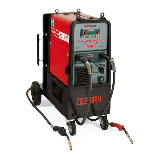
INSTRUCTION MANUAL FOR WIRE WELDING MACHINE
IMPORTANT: BEFORE STARTING THE EQUIPMENT,
READ THE CONTENTS OF THIS MANUAL, WHICH MUST
BE STORED IN A PLACE FAMILIAR TO ALL USERS FOR
THE ENTIRE OPERATIVE LIFE-SPAN OF THE MACHINE.
THIS EQUIPMENT MUST BE USED SOLELY FOR WEL-
DING OPERATIONS.
1 SAFETY PRECAUTIONS
WELDING AND ARC CUTTING CAN BE
HARMFUL TO YOURSELF AND OTHERS. The
user must therefore be educated against the hazards,
summarized below, deriving from welding operations.
For more detailed information, order the manual code
3.300.758
ELECTRIC AND MAGNETIC FIELDS - May be dangerous.
· Electric current following through any con-
ductor causes localized Electric and Ma-
gnetic Fields (EMF). Welding/cutting current
creates EMF fields around cables and po-
wer sources.
· The magnetic fields created by high currents may affect
the operation of pacemakers. Wearers of vital electronic
equipment (pacemakers) shall consult their physician be-
fore beginning any arc welding, cutting, gouging or spot
welding operations.
· Exposure to EMF fields in welding/cutting may have
other health effects which are now not known.
· All operators should use the followingprocedures in or-
der to minimize exposure to EMF fields from the welding/
cutting circuit:
- Route the electrode and work cables together
- Secure them with tape when possible.
- Never coil the electrode/torch lead around your body.
- Do not place your body between the electrode/torch
lead and work cables. If the electrode/torch lead
cable is on your right side, the work cable should also
be on your right side.
- Connect the work cable to the workpiece as close as
possible to the area being welded/cut.
- Do not work next to welding/cutting power source.
EXPLOSIONS
• Do not weld in the vicinity of containers under
pressure, or in the presence of explosive dust, gases
or fumes.
• All cylinders and pressure regulators used in welding ope-
rations should be handled with care.
ELECTROMAGNETIC COMPATIBILITY.
This machine is manufactured in compliance with the in-
structions contained in the standard IEC 60974-10 (CL.
A), and must be used solely for professional purposes in
an industrial environment. There may be potential diffi-
culties in ensuring electromagnetic compatibility in non-
industrial environments.
H.F FREQUENCY
• High frequency (H.F.) can interfere with radio
navigation, safety services, computers, and com-
munications equipment
10
• Have only qualified persons familiar with electronic
equipment perform this installation.
• The user is responsible for having a qualified electrician
promptly correct any interference problem resulting
from the installation.
• If notified by the FCC about interference, stop using the
equipment at once.
• Have the installation regularly checked and maintained.
• Keep high-frequency source doors and panels tight-
ly shut, keep spark gaps at correct setting, and use
grounding and shielding to minimize the possibility of
interference.
DISPOSAL OF ELECTRICAL AND ELECTRONIC
EQUIPMENT.
Do not dispose of electrical equipment together
with normal waste!In observance of European
Directive 2002/96/EC on Waste Electrical and Electronic
Equipment and its implementation in accordance with
national law, electrical equipment that has reached the
end of its life must be collected separately and returned
to an environmentally compatible recycling facility. As the
owner of the equipment, you should get information on
approved collection systems from our local representati-
ve. By applying this European Directive you will improve
the environment and human health!
IN CASE OF MALFUNCTIONS, REQUEST ASSISTANCE
FROM QUALIFIED PERSONNEL.
1.1 WARNING LABEL
The following numbered text corresponds to the label
numbered boxes.
B. Drive rolls can injure fingers.
C. Welding wire and drive parts are at welding voltage
during operation-keep hands and metal objects away.
1
Electric shock from welding electrode or wiring can
kill.
1.1 Wear dry insulating gloves. Do not touch electrode
with bare hand. Do not wear wet or damaged gloves.
1.2 Protect yourself from electric shock by insulating
yourself from work and ground.
1.3 Disconnect input plug or power before working on
machine.
2
Breathing welding fumes can be hazardous to your
health.
2.1 Keep your head out of fumes.
2.2 Use forced ventilation or local exhaust to remove
fumes.
2.3 Use ventilating fan to remove fumes.
3 Welding sparks can cause explosion or fire.
3.1 Keep flammable materials away from welding.
3.2 Welding sparks can cause fires. Have a fire extingui-
sher nearby and have a watchperson ready to use it.
3.3 Do not weld on drums or any closed containers.
4
Arc rays can burn eyes and injure skin.
4.1 Wear hat and safety glasses. Use ear protection and
button shirt collar. Use welding helmet with correct
shade of filter. Wear complete body protection.
Advertisement
Table of Contents

Related Manuals for Cebora JAGUAR SOUND MIG 2060


Summary of Contents for Cebora JAGUAR SOUND MIG 2060
-
Page 1: Instruction Manual For Wire Welding Machine
INSTRUCTION MANUAL FOR WIRE WELDING MACHINE IMPORTANT: BEFORE STARTING THE EQUIPMENT, • Have only qualified persons familiar with electronic READ THE CONTENTS OF THIS MANUAL, WHICH MUST equipment perform this installation. BE STORED IN A PLACE FAMILIAR TO ALL USERS FOR • The user is responsible for having a qualified electrician THE ENTIRE OPERATIVE LIFE-SPAN OF THE MACHINE. -
Page 2: Explanation Of Technical Specifications
Secondary voltage with current I2 Rated supply voltage 1~ 50/60Hz 50- or 60-Hz single-phase power supply. I1 Max Max. absorbed current at the corresponding current I2 and voltage U2. I1 eff This is the maximum value of the actual current absorbed, considering the duty cycle. - Page 3 Fig. 1 LED AG - Hold. 4 DESCRIPTION OF CONTROL PANEL (Fig. 2) May not be selected. It signals that the values shown on the displays AL and AM (normally Amperes and Volts) are AE selection key. those used during last welding. Activated at the end of Each brief pressure selects the size, adjustable via the each welding session.
- Page 4 Fig. 2 Display AL. LED AP Pulsed MIG. In all welding processes, it numerically displays the Shows that the selected process is the synergic MIG selections made via the selection key AE and adjusted Pulsed. via the knob AI. For the welding current (LED AD) it displays the amperes. LED AQ SYNERGIC MIG.
-
Page 5: Service Functions
To delete a saved number, press for at least 3 seconds well suited to weld aluminum. key AV, turn knob AI until the display ALshows the 3 currents are available that can be used in welding by abbreviation DEL and press the key againAV for 3 more means of the welding torch start button. - Page 6 6- PrF (Pre-gas). DdP= 0,1÷3 m/min The adjustment may range from 0 to 3 seconds. 7- Pof (post-gas). Reference The adjustment may range from 0 to 30 seconds. speed 8- Acc (soft-start ). The adjustment may range from 0 to 100%. It is the wire speed, expressed as a percentage of the speed set for the welding, before the wire touches the = 25÷75% di...
-
Page 7: Installation
16 - dSt Legal Time Selection. (e.g. 0 Winter, 1 Summer) 17- Fac. (factory). The purpose is to return the welding machine to the original settings provided by the manufacturer. With the function selected, the display AM shows noP = restores the welding machine to the original settings disregarding the stored programs, Prg = deletes all stored programs and ALL = restores the welding machine to the original... -
Page 8: Generator Maintenance
8 ACCESSORIES 8.1 MIG WELDING TORCH ART. 1242 Air-cooled CEBORA MIG welding torch 280 A 3,5. 8.2 PUSH-PULL UP/DOWN WELDING TORCH, air cooled, ART. 2003 and 2009. 8.3 Cooling unit Art. 1683 8.4 Water-cooled MIG torch Art. 1241 9 MAINTENANCE... - Page 9 QUESTA PARTE È DESTINATA ESCLUSIVAMENTE AL PERSONALE QUALIFICATO. THIS PART IS INTENDED SOLELY FOR QUALIFIED PERSONNEL. DIESER TEIL IST AUSSCHLIEßLICH FÜR DAS FACHPERSONAL BESTIMMT. CETTE PARTIE EST DESTINEE EXCLUSIVEMENT AU PERSONNEL QUALIFIE. ESTA PARTE ESTÁ DESTINADA EXCLUSIVAMENTE AL PERSONAL CUALIFICADO. ESTA PARTE È...
- Page 10 POS DESCRIZIONE DESCRIPTION POS DESCRIZIONE DESCRIPTION CHIUSURA CLOSING MANICO HANDLE ROSETTA WASHER LATERALE SIN. INFERIORE LEFT LOWER SIDE PANEL FRONT FIXED LEFT SIDE GOLFARA EYEBOLT LATERALE FISSO SIN. ANT. PANEL TAPPO USB USB CAP LATERALE MOBILE HINGED SIDE PANEL COMMUTATORE SWITCH CERNIERA HINGE...
- Page 12 POS DESCRIZIONE DESCRIPTION POS DESCRIZIONE DESCRIPTION PROTEZIONE TRAINAFILO WIRE FEED UNIT WIRE FEED PROTECTION MOTORIDUTTORE MOTORIDUTTORE WIRE FEED MOTOR CORPO TRAINAFILO COMPLETE WIRE FEED BODY COMPLETO ENCODER ENCODER RULLO TRAINAFILO WIRE FEED ROLLER MOTORIDUTTORE COMPLETE WIRE FEEDER COMPLETO MOTOR POMELLO KNOB BLOCCAGGIO GRADUATO ADJUSTMENT KNOB...
- Page 13 POS DESCRIZIONE DESCRIPTION POS DESCRIZIONE DESCRIPTION CORPO TRAINAFILO COMPLETE WIRE TRAINAFILO DESTRO RIGHT WIRE FEED UNIT COMPLETO FEED BODY ENCODER ENCODER RULLO TRAINAFILO WIRE FEED ROLLER SUPPORTO PREMIRULLO ROLLER PRESSER SUPPORT POMELLO KNOB BLOCCAGGIO GRADUATO ADJUSTMENT KNOB GRUPPO TRAINAFILO WIRE FEED UNIT GUIDAFILO WIRE DRIVE PIPE ASSY INGRANAGGIO...
- Page 14 CARRELLO PER TRASPORTO GENERATORE TROLLEY FOR TRANSPORTATION OF THE POWER SOURCE POS DESCRIZIONE DESCRIPTION POS DESCRIZIONE DESCRIPTION SUPPORTO CAVI CABLES SUPPORT TAPPO APPOGGIO BOMBOLA GAS CYLINDER SUPPORT SUPPORTO RUOTE WHEELS SUPPORT CINGHIA BELT RUOTA PIROETTANTE SWIVELING CASTOR SUPPORTO BOMBOLA GAS CYLINDER SUPPORT PANNELLO INTERNO INSIDE PANEL FONDO...
- Page 16 CODIFICA COLORI WIRING DIAGRAM CODIFICA COLORI WIRING DIAGRAM CABLAGGIO ELETTRICO COLOUR CODE CABLAGGIO ELETTRICO COLOUR CODE NERO BLACK NROSA-NERO PINK-BLACK ROSSO GRIGIO-VIOLA GREY-PURPLE GRIGIO GREY BIANCO-VIOLA WHITE-PURPLE BIANCO WHITE BIANCO-NERO WHITE-BLACK VERDE GREEN GRIGIO-BLU GREY-BLUE VIOLA PURPLE BIANCO-ROSSO WHITE-RED GIALLO YELLOW GRIGIO-ROSSO GREY-RED...
- Page 18 CEBORA S.p.A - Via Andrea Costa, 24 - 40057 Cadriano di Granarolo - BOLOGNA - Italy Tel. +39.051.765.000 - Fax. +39.051.765.222 www.cebora.it - e-mail: cebora@cebora.it...