Advertisement
Thank you for purchasing "SmartCell 212 /112" product.
Quasar Communication Systems Ltd. and its distributors assume no
responsibility for any damage or loss resulting from the use of its products or
this user manual. Quasar Communication Systems Ltd and its distributors
assume no responsibility for any loss or claims by third parties, which may
arise through the use of its products.
Registration and Type Approval
Smartcell 212 /112 carries CE Certification, Australia AS/NZS3548
Corporate contacts
E-mail:
Web address:
© Quasar Communication Systems Ltd. All rights reserved. Quasar, the
Quasar Logo, CelluLink and CellBox are registered trademarks of Quasar
Communication Systems Ltd. Other product and brand names may be
trademarks or registered trademarks of their respective owners.
September 2003
sales@quasar.biz
www.quasar.biz
Advertisement
Table of Contents

Summary of Contents for Quasar SmartCell 212
- Page 1 Quasar Communication Systems Ltd. and its distributors assume no responsibility for any damage or loss resulting from the use of its products or this user manual. Quasar Communication Systems Ltd and its distributors assume no responsibility for any loss or claims by third parties, which may arise through the use of its products.
-
Page 3: Packing List
Private Branch Exchange (PBX) system. The SmartCell 212 has a standard ISDN BRI “S0” interface on the Line side and connects with 2 channels to any GSM cellular network to create a cellular gateway. - Page 4 SmartCell 212/112 SmartCell 212/112 unit Cables Power Cable ISDN Interface Cable SYNC IN Cable Antenna 2 Bags with Screws & Dowel pins Drill Template...
-
Page 5: Safety Precautions
Non-observance of these conditions and safety instructions can result in personal injury or in property damage. The Smartcell 212 system complies with the standard IGC 950. All connected equipment must comply with the applicable safety standards: EN 55022... -
Page 6: Product Description
SmartCell 212/112 3. Product Description 3.1 Technical Specifications* Power supply Supply voltage (secondary) 12V DC Supply current 2 A max. Operating temperature 0 ºC to 40 ºC Full CE Standards ISDN specifications Line interface BRI – S/T point reference (indoor only), Type NT or partial TE. -
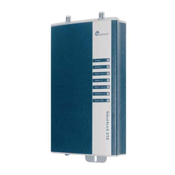
Page 7: Led Indications
3.2 LED Indications Description Operation Power Indicates the On–the SmartCell 112/212 is status of the powered on. power Off–the SmartCell 112/212 is connection. powered off. Status 1 Indicates the Off–the channel is idle and no SmartCell calls are being handled. On–the channel is handling a operational call. - Page 8 SmartCell 212/112 Description Operation STATUS 2 Indicates the Off–the channel is idle and no SmartCell calls are being handled. On–the channel is handling a operational call. status of Slow blinking–the SmartCell channel 2. 112/212 is initialising following power up or is being programmed.
-
Page 9: Installation Instructions
4. SmartCell 212/112 Installation 4.1 Installation Instructions 4.1.1 Locate template on the wall and mark screw location 4.1.2 Bore 3 holes. - Page 10 SmartCell 212/112 4.1.3 Insert 3 dowel pins. 4.1.4 Tighten the two upper screws. Leave a gap of 3mm minimum between the screw head and the wall. 4.1.5 Mount the SmartCell 212/112 on the 2 screws.
- Page 11 4.1.6 Tighten the lower screw. 4.1.7 Connect cables. NT cable Power cable SYNC IN cable (only if necessary)
- Page 12 SmartCell 212/112 4.1.8 Connect antennas. Antenna Bracket...
-
Page 13: Configuration Of The Pabx
Comments Define the ISDN interface (TE point Required reference, point to point with TEI=0.) On LCR (Least Cost Routing) enabled Optional SmartCell 212/112 systems, set the CLI programmed to becomes transparent to internal identify cellular prefixes. callers. Use only the original ISDN cable (straight) Required to insure proper operation. -
Page 14: Cable Connections
SmartCell 212/112 4.4 Cable Connections 4.4.1 Normal Connection In normal connection, the 212/112 is used as the NT side and the PABX as the TE side. The Sync (timing) is delivered from the 212/112 to the PABX over the ISDN cable. The Sync IN/TE port of the 212/112 is not used. - Page 15 4.4.3 External Sync mode In this mode, the PABX is used as the TE side and the 212/112 is used as the NT side of the ISDN connection. However, the Sync (timing) is delivered from the PABX to the 212/112 over a second cable (a straight RJ-45 cable, provided with 212/112).
-
Page 16: Getting Started
SmartCell 212/112 4.5 Getting Started 4.5.1 After making all connections and installing the SIM cards, make sure the POWER LED is lit. If it is not, make sure that the power supply is properly connected to the unit and to the AC mains.