Table of Contents
Advertisement
Quick Links
Advertisement
Table of Contents

Related Manuals for HP E4418B


Summary of Contents for HP E4418B
- Page 1 User’s Guide HP E4418B Power Meter HP Part no. E4418-90032 December, 1998...
- Page 2 © Copyright Hewlett-Packard Company All rights reserved. Reproduction, adaptation, or translation without prior written permission is prohibited, except as allowed under the copyright laws. Printed in the UK. HP E4418B User’s Guide...
-
Page 3: Legal Information
For warranty service or repair, this product must be returned to a service facility designated by HP. Buyer shall prepay shipping charges to HP and HP shall pay shipping charges, duties, and taxes for products returned to HP from another country. -
Page 4: Limitation Of Warranty
MERCHANTABILITY AND FITNESS FOR A PARTICULAR PURPOSE. Exclusive Remedies THE REMEDIES PROVIDED HEREIN ARE BUYER’S SOLE AND EXCLUSIVE REMEDIES. HP SHALL NOT BE LIABLE FOR ANY DIRECT, INDIRECT, SPECIAL, INCIDENTAL, OR CONSEQUENTIAL DAMAGES, WHETHER BASED ON CONTRACT, TORT, OR ANY OTHER LEGAL THEORY. -
Page 5: Equipment Operation
For continued protection against fire hazard, replace the line fuse(s) only with fuses of the same type and rating (for example, normal blow, time delay, etc.). The use of other fuses or material is prohibited. HP E4418B User’s Guide... -
Page 6: General Safety Considerations
This terminal is for use where the earthing cannot be assured. At least an 18AWG earthing conductor should be used in such an instance, to ground the instrument to an assured earth terminal. HP E4418B User’s Guide... -
Page 7: Iec 1010-1 Compliance
This product has been designed and tested for compliance with IEC 60529 (1989) Degrees of Protection Provided by Enclosures (IP Code). Level IPx4 is attained if, and only if, the carry case( part number HP 34141A) is fitted. User Environment... -
Page 8: Regulatory Information
Australian EMC Regulations The C-Tick mark is a registered trademark of the Spectrum Management Agency of Australia. This signifies compliance with the Australian EMC Framework Regulations under the terms of the Radiocommunications Act of 1992. viii HP E4418B User’s Guide... -
Page 9: Declaration Of Conformity
South Queensferry, Scotland 22 October 1998 Location Date R.M. Evans / Quality Manager Europe Contact: Your local Hewlett-Packard Sales and Service Office or Hewlett-Packard GmbH, Department 2Q / Standards Europe, Herrenberger Strasse 130, D7030 Boblinger (Fax; +49-7031-143143). HP E4418B User’s Guide... -
Page 10: List Of Related Publications
List of Related Publications List of Related Publications The HP E4418B User’s Guide is also available in the following languages: • English Language User’s Guide - Standard • German Language User’s Guide - Option ABD • Spanish Language User’s Guide - Option ABE •... -
Page 11: Hp E4418B Options
HP E9287A Spare battery pack - for instruments fitted with option 001 only • HP 34397A 12 Vdc to 115 Vac inverter (Option 0E3 230 V) • The following HP power sensor cables are available: HP 11730A 1.5 m (7.5 ft) HP 11730B 3 m (10 ft) HP 11730C 6.1 m (20 ft) -
Page 12: About This Guide
This chapter lists the error messages that may appear as you are working with the power meter. Each description contains information to help you diagnose and solve the problem. Chapter 5: Specifications This chapter lists the power meter’s specifications and describes how to interpret these specifications. HP E4418B User’s Guide... -
Page 13: Table Of Contents
Installation Instructions ............vii Regulatory Information ............. viii Sound Emission ..............viii Australian EMC Regulations..........viii List of Related Publications ............x HP E4418B Options ..............xi Available Accessories ............xi About this Guide ................. xii Getting Started ..................1-1 Introduction................... 1-2 Turning On the Power Meter ............ - Page 14 Zeroing and Calibrating Using TTL Inputs ......2-12 Making Measurements with the HP E-Series Power Sensors ................2-15 Procedure ................2-15 Making Measurements with the HP 8480 Series Power Sensors ................2-17 Procedure ................2-17 Making Measurements using Sensor Calibration Tables... 2-19 Selecting a Sensor Calibration Table ........
- Page 15 Returning Your Power Meter for Service......2-80 Menu Reference................... 3-1 Introduction................... 3-2 The Front Panel Menu Maps ............3-3 dBm/W Menu ................3-3 Frequency/Cal Fac Menu ............3-4 Meas Setup Menu ..............3-5 Rel/Offset Menu ..............3-6 Save/Recall Menu ..............3-6 HP E4418B User’s Guide Contents-3...
- Page 16 Environmental Characteristics ............ 5-15 General Conditions..............5-15 Operating Environment ............5-15 Storage Conditions ..............5-15 General ..................5-16 Dimensions ................5-16 Weight ..................5-16 Safety ..................5-16 Remote Programming ............5-16 Non-Volatile Memory ............. 5-17 Contents-4 HP E4418B User’s Guide...
- Page 17 Interface Overview Examples ........... 2-57 2-20 Test Setup for Recording Swept Measurements ...... 2-59 2-21 “Save/Recall” Screen ..............2-62 2-22 How Measurements are Calculated.......... 2-63 2-23 Replacing the Fuse ..............2-73 Error Annunciator Position............4-2 HP E4418B User’s Guide Contents-5...
- Page 18 Contents-6 HP E4418B User’s Guide...
-
Page 19: List Of Tables
List of Tables Page Connecting the HP 8480 Series Power Sensors During Calibration ..............2-11 TTL Inputs Control Logic............2-12 TTL Input Timing Diagram 1 ........... 2-13 TTL Inputs Timing Diagram 2 ..........2-14 Measurement Units ..............2-32 Range of Values for Window Limits ......... 2-45 Zero Set Specifications .............. -
Page 20: Hp E4418B User's Guide
Contents-8 HP E4418B User’s Guide... -
Page 21: Getting Started
Getting Started... -
Page 22: Introduction
When some hardkeys are selected the corresponding softkey labels are displayed on the power meter display. If you are using the power meter remotely refer to the HP E4418B/4419B Programming Guide for remote operating details. -
Page 23: Turning On The Power Meter
Prior to making your first measurement you must zero and calibrate the sensor and meter combination. Refer to Chapter 2 for further information if you are not familiar with zeroing, calibrating or making measurements with a power meter. HP E4418B User’s Guide... -
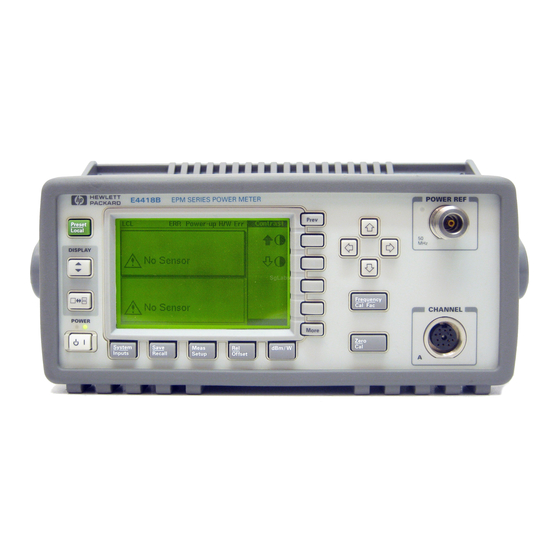
Page 24: The Front Panel At A Glance
However, if you are in remote mode (that is, HP-IB, RS232 or RS422 operation), then pressing this hardkey places the power meter in local mode provided local lock out (LLO) is not enabled. - Page 25 Refer to Chapter 3 for further information about these hardkeys and their softkey menus. 8. Channel Input. The HP E4418B has one sensor input. Power meters configured with options 002 or 003 have the sensor inputs on the rear panel and the front panel.
- Page 26 This hardkey allows you to move back one level in the Prev softkey menu. Repeatedly pressing accesses a menu which Prev allows you to increase and decrease the display contrast. 12. Softkeys. These four keys are used to make a selection from the menus. HP E4418B User’s Guide...
-
Page 27: The Display Layout
(remote, HP-IB, RS232 or RS422 operation) or “LCL” (local, front panel operation). For HP-IB operation, the second field displays “TLK” if the power meter is addressed to talk or “LSN” if it is addressed to listen. The third field indicates an “SRQ” (service request). - Page 28 Find the table entry which matches your display and use the reference number in the left-hand column to look up Table 1-2 for the combination of sensor type and correction being applied to the HP E4418B User’s Guide...
- Page 29 Display Line CF:xxx.x% CF:xxx.x% xxx.xyHz(a) xxx.xyHz (nn) xxx.xyHz (nn,a) xxx.xyHz xxx.xyHz Where “y” is the frequency multiplier (M or G), “nn” is the sensor calibration table number and “a” is the frequency dependent offset table letter. HP E4418B User’s Guide...
- Page 30 Directly entered Calibration Factor 8480 From offset table Series Frequency dependent None Sensors - from selected sensor calibration table From offset table Frequency dependent None E-Series - downloaded directly Sensors from sensor From offset table 1-10 HP E4418B User’s Guide...
-
Page 31: Selecting Your Display Layout
Two Windows One Window Select using Select using Meas , Display Format Setup Upper Lower Window Window Digital Analog Display Display Select using Meas , Display Format Setup Digital Analog Digital Analog Display Display Display Display HP E4418B User’s Guide 1-11... - Page 32 Meas 4.Press Display Format Setup (Dgtl should be Meter Dgtl Anlg highlighted). The display shows a digital window. 5.Press . The display now shows two digital windows. 1-12 HP E4418B User’s Guide...
- Page 33 . The upper window is now the selected window and is highlighted by the black box. 7.Press (Anlg Meter Dgtl Anlg should be highlighted). The upper window now displays an analog meter. 8.Select the digital display using HP E4418B User’s Guide 1-13...
-
Page 34: Window Symbols
The wait symbol is displayed when the power meter is carrying out a procedure but no action is required from you. The symbol may appear directly in the measurement window or in a pop up window. It may appear, for example, during, zeroing or calibration. 1-14 HP E4418B User’s Guide... -
Page 35: Of N Entry Window
This pop up window is displayed when you are required to modify numeric or alphanumeric data. The keys move the position of the cursor. keys increment and decrement the alphanumeric digit on which the cursor is currently positioned. HP E4418B User’s Guide 1-15... -
Page 36: The Rear Panel At A Glance
This connector allows the power meter to be controlled remotely using the Hewlett-Packard Interface Bus. 7. RS232/422 This connector allows the power meter to be controlled remotely using either the RS232 or RS422 serial interface standards. 1-16 HP E4418B User’s Guide... - Page 37 It provides a TTL logic level output when a measurement exceeds a predetermined limit. TTL inputs are also provided to initiate zero and calibration cycles. 10. Ground Connector Binding post, accepts 4 mm plug or bare-wire connection. HP E4418B User’s Guide 1-17...
-
Page 38: Adjusting The Carrying Handle
Getting Started Adjusting the Carrying Handle Adjusting the Carrying Handle To adjust the position, grasp the handle by the sides and pull outward. Rotate the handle to the desired position. Bench top viewing positions Carrying position 1-18 HP E4418B User’s Guide... -
Page 39: Rack Mounting The Power Meter
You can mount the power meter in a standard 19 inch rack cabinet using one of three optional kits. Instructions and mounting hardware are included with each rack mounting kit. Any HP System II instrument can be rack mounted beside the HP E4418B power meter. - Page 40 To rack mount two instruments side by side, order option 909, or lock-link kit 5061-9694 and flange kit 5063-9212. To install one or two instruments in a sliding support shelf, order shelf 5063-9255, and slide kit 1494-0015 (for a single instrument, also order filler panel 5002-3999). 1-20 HP E4418B User’s Guide...
-
Page 41: Power Meter Operation
Power Meter Operation... -
Page 42: Introduction
“Zeroing and Calibrating the Power Meter”, on page 2-7. • “Calibrating the Power Meter”, on page 2-8. • “Making Measurements with the HP E-Series Power Sensors”, on page 2-15. • “Making Measurements with the HP 8480 Series Power Sensors”, on page 2-17. -
Page 43: Battery Operation (Option 001)
A soft carry/operating case is available which makes it easy to transport and operate your power meter in installation and maintenance environments. To obtain a carry case order HP part number 34141A. Caution Do not attempt to recharge the power meter or operate the power meter from an ac power source while it is contained in the carry case. -
Page 44: Charging Times
Working with the backlight off reduces the drain on the battery and increases the operating time available by approximately 50%. The display can be comfortably read in ambient daylight with the backlight off. HP E4418B User’s Guide... -
Page 45: Battery Removal/Replacement
Battery Removal/Replacement The battery unit is easily removed and replaced. Follow the instructions given in Figure 2-2. To obtain a replacement battery unit order HP part number E9287A (this can only be used in power meters with option 001 installed). -
Page 46: Battery Removal/Replacement
Support the closure assembly on a flat surface. Pinch the release tab between finger and thumb while - lightly pressing down on the battery module. Replacing the battery is basically a reversal of the removal procedure. Release Tab Battery Module Closure Assembly HP E4418B User’s Guide... -
Page 47: Zeroing And Calibrating The Power Meter
If you calibrate the sensor before zeroing it, the message changes to “Please Zero ChA”. The Zero/Cal Lockout facility can be enabled/disabled through either the System Inputs menu or the Zero Cal menu as follows: System Press Must Cal Off More Inputs HP E4418B User’s Guide... -
Page 48: Calibrating The Power Meter
An essential part of calibrating is setting the correct reference calibration factor for the power sensor you are using. The HP 8480 series power sensors require you to set the reference calibration factor. The HP E-series power sensors set the reference calibration factor automatically. -
Page 49: Calibration Procedure Using Hp 8480 Series Power Sensors
• Connect the power sensor to the POWER REF output. • Press Calibration Procedure using HP 8480 Series Power Sensors The following procedure describes how you calibrate the power meter with the HP 8480 series power sensors. Note V8486A and W8486A sensors For most 8480 series sensors the correct (A type or D type) linearity correction table is automatically selected. - Page 50 To calibrate the power meter with a power sensor whose reference calibration factor is 99.8%. Zero • Press • Press . Use the hardkeys to Ref CF enter 99.8. Press • Connect the power sensor to the POWER REF output. • Press 2-10 HP E4418B User’s Guide...
-
Page 51: Connecting The Hp 8480 Series Power Sensors During Calibration
HP 8481H HP 8482A HP 8482H HP 8481D Prior to the power meter being calibrated an HP 11708A 30 dB HP 8484A reference attenuator should be connected between the power sensor and the reference calibrator. This attenuator must be removed from the power sensor input prior to making measurements. -
Page 52: Zeroing And Calibrating Using Ttl Inputs
TTL Input 2 Ground Ground The TTL inputs are active low and control the zero and calibration functions as shown in Table 2-2 Table 2-2: TTL Inputs Control Logic Input 1 Input 2 Operation None ZERO 2-12 HP E4418B User’s Guide... - Page 53 Time for zero/cal operation to complete. Zero: 10 s (8480 series) 12 s (E series) Cal: 6 s (8480 series) 7 s (E series) All timings based on 100 ms firmware polling. HP E4418B User’s Guide 2-13...
- Page 54 Cal: 6 s (8480 series) 7 s (E series) All timings based on 100 ms firmware polling. If both TTL inputs are simultaneously low under any circumstances other than those shown above, the operation is undefined. 2-14 HP E4418B User’s Guide...
-
Page 55: Making Measurements With The Hp E-Series Power Sensors
Power Meter Operation Making Measurements with the HP E-Series Power Sensors Making Measurements with the HP E-Series Power Sensors This section describes how to make continuous wave measurements using the HP E-series power sensors. The HP E-series power sensors have their sensor calibration tables stored in EEPROM. - Page 56 Power Meter Operation Making Measurements with the HP E-Series Power Sensors Example To make a measurement using an HP E-series power sensor. The frequency of the signal to be measured is 100 MHz. • Disconnect the power sensor from any source.
-
Page 57: Making Measurements With The Hp 8480 Series Power Sensors
Making Measurements with the HP 8480 Series Power Sensors This section applies to all HP 8480 series power sensors. It does not apply to the HP E-series power sensors. For the HP 8480 series power sensors there are two methods of providing... - Page 58 Power Meter Operation Making Measurements with the HP 8480 Series Power Sensors up window. Modify this reference calibration factor (see below) as desired. to modify the digit on which the cursor is currently positioned. to move to other digits. 6. To confirm your choice press 7.
-
Page 59: Making Measurements Using Sensor Calibration Tables
Making Measurements using Sensor Calibration Tables Making Measurements using Sensor Calibration Tables This section applies to all HP 8480 series power sensors. It does not apply to the HP E-series power sensors. For the HP 8480 series power sensors there are two methods of providing... -
Page 60: Making The Measurement
. The power meter displays the Freq frequency in a pop up window. Modify this frequency (see below) as desired. to modify the digit on which the cursor is currently positioned. to move to other digits. 2-20 HP E4418B User’s Guide... -
Page 61: Editing Sensor Calibration Tables
To view the sensor calibration tables currently stored in the power meter, System press . The “Sensr Tbls” screen is Tables Sensor Cal Tables Inputs displayed as shown in Figure 2-4. Figure 2-5: “Edit Cal” Screen HP E4418B User’s Guide 2-21... - Page 62 1. DEFAULT is a sensor calibration table in which the reference calibration factor and calibration factors are 100%. This sensor calibration table can be used during the performance testing of the power meter. 2. The HP 8482B and HP 8482H power sensors use the same data as the HP 8482A. 2-22...
- Page 63 If you measure a signal with a frequency outside the frequency range defined in the sensor calibration table, the power meter uses the highest or lowest frequency point in the sensor calibration table to calculate the calibration factor. HP E4418B User’s Guide 2-23...
- Page 64 94.3 3 MHz 98.4 14 GHz 93.2 10 MHz 99.3 15 GHz 30 MHz 98.7 16 GHz 100 MHz 97.8 17 GHz 92.7 300 MHz 97.5 18 GHz 91.8 1 GHz 97.2 2 GHz 96.4 2-24 HP E4418B User’s Guide...
- Page 65 35 GHz 94.4 34.5 GHz 36 GHz 93.7 35 GHz 97.6 37 GHz 94.9 36 GHz 38 GHz 93.5 37 GHz 98.2 39 GHz 93.9 38 GHz 97.4 40 GHz 92.3 39 GHz 97.6 40 GHz HP E4418B User’s Guide 2-25...
- Page 66 47 GHz 86.4 29 GHz 94.4 48 GHz 85.3 30 GHz 49 GHz 84.7 31 GHz 93.7 50 GHz 82.9 32 GHz 93.8 33 GHz 34 GHz 93.2 34.5 GHz 93.5 35 GHz 93.1 36 GHz 2-26 HP E4418B User’s Guide...
-
Page 67: Making Measurements Using Frequency Dependent Offset Tables
You can select a frequency dependent offset table for use by pressing System . The “State” Tables Freq Dep Offset Table Off On Inputs field indicates if any frequency dependent offset tables are currently selected. The “Offset Tbls” screen is displayed as shown in Figure 2-6. HP E4418B User’s Guide 2-27... -
Page 68: Making The Measurement
. The power meter displays the Freq frequency in a pop up window. Modify this frequency (see below) as desired. to modify the digit on which the cursor is currently positioned. to move to other digits. 2-28 HP E4418B User’s Guide... -
Page 69: Editing Frequency Dependent Offset Tables
To view the frequency dependent offset tables currently stored in the System power meter, press . The “Offset Tables Freq Dep Offset Inputs Tbls” screen is displayed as shown in Figure 2-6. Figure 2-7: “Edit” Screen HP E4418B User’s Guide 2-29... - Page 70 . You are prompted for the frequency and offset. The entry Insert is sorted by frequency. 5. To remove a frequency dependent offset table entry, use the hardkeys to select the entry, press Delete . If 2-30 HP E4418B User’s Guide...
- Page 71 If you measure a signal with a frequency outside the frequency range defined in the frequency dependent offset table, the power meter uses the highest or lowest frequency point in the frequency dependent offset table to calculate the offset. HP E4418B User’s Guide 2-31...
-
Page 72: Setting The Units Of Measurement
Relative Mode Off Relative Mode On Measurement Mode Linear Linear Single Channel Watt is “On”) 1. When relative mode is on (that is, Rel Off On , the Offset measurement is compared to a reference value. 2-32 HP E4418B User’s Guide... -
Page 73: Selecting Units Of Measurement From The Softkeys
Some softkeys may be grayed out so that an invalid value cannot be entered. Pressing Increment Multiplier Decrement Multiplier increases or decreases the multiplier shown in front of . Pressing after the correct multiplier has been selected confirms the entry. HP E4418B User’s Guide 2-33... -
Page 74: Making Relative Measurements
“On” when is pressed. Rel Off On Successive measurements are now displayed relative to the reference value. The relative mode can be disabled and re-enabled simply by pressing Rel Off On 2-34 HP E4418B User’s Guide... -
Page 75: Setting The Resolution
. The current setting of the resolution is highlighted Setup on the softkey. Resolution 1 2 3 4 2. To change this setting press until the Resolution 1 2 3 4 required resolution setting is highlighted. HP E4418B User’s Guide 2-35... -
Page 76: Setting Offsets
The display offset function provides a method for entering display offset values. If either a channel or a display offset is set then “Ofs” is displayed. To enter a display offset on the currently selected window: 1. Press Offset Offset 2-36 HP E4418B User’s Guide... -
Page 77: Effect Of Offsets On A Channel Measurement
Ch Input with Ch Offset and READING Ch Input Ch Offset Display Offset Display ON POWER † †† Offset Offset METER DISPLAY System Input Settings Offset † Channel Offset entered using Inputs †† Display Offset entered using Offset Offset HP E4418B User’s Guide 2-37... -
Page 78: Setting Averaging
Figure 2-9 lists the number of readings averaged for each range and resolution when the power meter is in auto filter mode and is set to normal speed mode (refer to the HP E4418B/E4419B Programming Guide for details of the readings averaged in the other speed modes). -
Page 79: Step Detection
The filter can be disabled and re-enabled simply by pressing Filter Off On Step Detection To reduce the filter settling time after a significant step in the measured power the filter can be set to re-initialise upon detection of a step HP E4418B User’s Guide 2-39... - Page 80 filter modes. To set step detection: System 1. Press Input Settings More Inputs 2. Press the Filter softkey to access the filter menu. 3. Use the softkey to enable /disable step Step Det Off On detection. 2-40 HP E4418B User’s Guide...
-
Page 81: Measuring Pulsed Signals
The default value is 1.000%. If duty cycle is enabled then “Dty Cyc” is displayed. Note Pulse measurements are not recommended using HP E4412A and E4413A power sensors. An example of a pulsed signal is shown in Figure 2-10. Figure 2-10: Pulsed Signal... - Page 82 In order to ensure accurate pulse power readings, the input signal must be pulsed with a rectangular pulse. Other pulse shapes (such as triangle, chirp or Gaussian) will cause erroneous results. The pulse power on/off ratio must be much greater than the duty cycle ratio. 2-42 HP E4418B User’s Guide...
-
Page 83: Setting Measurement Limits
3. To confirm your choice press the appropriate measurement units. Limits can be disabled and re-enabled simply by pressing Limits Off On A typical application for this feature is shown in Figure 2-11. HP E4418B User’s Guide 2-43... -
Page 84: Setting Window Limits
The power meter can be configured to verify the current measurement in either window against predefined upper and/or lower limit values. The range of values that can be set for the upper and lower limits and the 2-44 HP E4418B User’s Guide... -
Page 85: Range Of Values For Window Limits
TTL output represents an over limit condition, under limit condition or both. The TTL connector is an RJ-45 series shielded modular jack assembly with the TTL output pins connected as shown in Figure 2-13. HP E4418B User’s Guide 2-45... -
Page 86: Remote I/O Ttl Outputs
3. To confirm your choice press the appropriate measurement units. Limits can be disabled and re-enabled simply by pressing Limits Off On 2-46 HP E4418B User’s Guide... -
Page 87: Checking For Limit Failures
Limit failures are displayed in the appropriate field in the measurement window on the power meter’s display as shown in Figure 2-14. Note The same limit fail field is used by both channel and window limits. HP E4418B User’s Guide 2-47... -
Page 88: Pass/Fail Limit Indicators
-55 dBm. This is indicated with the text “Undr Lmt”. This measurement has failed as the result is more than the maximum limit level set of -60 dBm. This is indicated with the text “Over Lmt”. 2-48 HP E4418B User’s Guide... -
Page 89: Selecting A Digital Or Analog Display
The measurement windows can display the result in either a digital or analog format or both as shown in the following figures. Figure 2-15: Digital Display Figure 2-16: Analog Display Figure 2-17: Digital and Analog Display HP E4418B User’s Guide 2-49... - Page 90 µW Cancel Cancel Increment Increment Multiplier Multiplier More More Decrement Decrement Multiplier Multiplier Cancel Cancel Pressing Increment Multiplier increases or decreases the multiplier Decrement Multiplier 2-50 HP E4418B User’s Guide...
- Page 91 That is, it does not indicate when duty cycle, range hold, offset or relative mode are enabled. In addition, it does not indicate if the measurement is within the test limits if any are set. HP E4418B User’s Guide 2-51...
-
Page 92: Setting The Range
The power meter has no internal ranges which can be set. The only ranges that can be set are those of the HP E-series power sensors. With an HP E-series power sensor the range can be set either automatically or manually. -
Page 93: Configuring The Remote Interface
The address is stored in non-volatile memory, and does not change when the power is switched off, or after a remote interface reset. Your HP-IB bus controller has its own address. Avoid using the bus controller’s address for any instrument on the interface bus. -
Page 94: Rs232/Rs422
RS232/422 Connector The serial port connector is a 9 pin male D-type wired as shown in Figure 2-18. Figure 2-18: RS232/422 Pin Assignment RS232 RS422 CTS- 2 3 4 5 7 8 9 RTS+ CTS+ RTS- 2-54 HP E4418B User’s Guide... - Page 95 Xon/Xoff transmitter software handshake. When enabled “Xon” is highlighted, otherwise “None” is highlighted. 10. Press to toggle between enabling and disabling the Rx Pacing Xon/Xoff receiver software handshake. When enabled “Xon” is highlighted, otherwise “None” is highlighted. HP E4418B User’s Guide 2-55...
-
Page 96: Remote Interface Overview
Remote Interface Overview You can view a summary of your remote interface settings at any time by System pressing Remote Interface Interface Overview Inputs Examples of an HP-IB and RS422 interface overview are shown in Figure 2-19. 2-56 HP E4418B User’s Guide... -
Page 97: Interface Overview Examples
Power Meter Operation Configuring the Remote Interface Figure 2-19: Interface Overview Examples Pressing the softkey returns the power meter display to the Done previous screen. HP E4418B User’s Guide 2-57... -
Page 98: Programming Language Selection
You can select one of two languages to program the power meter from the remote interface. The language is SCPI when the power meter is shipped from the factory. The other language is the HP 437B programming language. The power meter complies with the rules and regulations of the 1995.0 version of SCPI (Standard Commands for Programmable Instruments). -
Page 99: Recorder Output
Output signal either on or off. The softkeys Max Power Min Power allow you to enter the input power level that you want to represent the maximum and 0 V minimum output voltage of the Recorder Output. HP E4418B User’s Guide 2-59... -
Page 100: Leveling A Source Output
-50 dBm (10 nW) -60 dBm (1 nW) To set the maximum value press and enter the Max Power appropriate value. 3. Press and enter 0 W. Min Power 4. Press to “On”. Output Off On 2-60 HP E4418B User’s Guide... -
Page 101: Saving And Recalling Power Meter Configurations
Saving and Recalling Power Meter Configurations To reduce repeated setup sequences, up to ten power meter configurations can be stored in the power meter’s non-volatile memory. The HP-IB address and command set, the data stored in the sensor calibration tables and the zeroing and calibration data are not stored by a preset. -
Page 102: Save/Recall" Screen
Power Meter Operation Saving and Recalling Power Meter Configurations Figure 2-21: “Save/Recall” Screen 2-62 HP E4418B User’s Guide... -
Page 103: How Measurements Are Calculated
Figure 2-22: How Measurements are Calculated Channel Functions Window Functions Upper Window Channel A Channel Duty Freq Dep Display Averaging Cal Factor Relative Offset Cycle Offset Offset Limits Window Recorder Limits Output Lower Window Display Relative Offset Window Limits HP E4418B User’s Guide 2-63... -
Page 104: Presetting The Power Meter
Presetting the Power Meter This section details the power meter’s preset conditions. The HP-IB address and command set, the data stored in the sensor calibration tables and the zeroing and calibration data are not affected by a preset. The calibration table selected is not affected. - Page 105 Must Cal Off/On • is set to “On” Backlight Zero • is set to 100%. Ref CF • is not affected. Must Cal Off/On • is set to “Off”. TTL Inputs Off/On HP E4418B User’s Guide 2-65...
-
Page 106: Self Test
“Not Present”. If a failure occurs the message “Power-up H/W Err” appears. Any errors are also written to the error queue and can be System examined in the “Errors” screen by pressing More Inputs Error List 2-66 HP E4418B User’s Guide... -
Page 107: Front Panel Selection Of Self Tests
The RS232 and RS422 loop back tests require a specially wired Note connector - refer to the E4418B/E4419B Service Guide. Each of these tests can be run individually. Information on the instrument self test and confidence check are described on page 2-68. Refer to “Test Descriptions”, on page 2-70 if you require a description of the other tests. - Page 108 1. Connect the power sensor to the POWER REF output (Refer to Table 2-1 on page 2-11 for connection requirements for the HP 8480 series power sensors). The power reference signal is turned on automatically after any key is pressed.
-
Page 109: Remote Testing
Communications Assembly (Implicit) The communications assembly is tested implicitly, in that the command will not be accepted or return a result unless the HP-IB interface is functioning correctly. Refer to “Test Descriptions”, on page 2-70 if you require a description of each individual test. -
Page 110: Test Descriptions
Four tests are available for the serial interface: UART configuration, local loop back, RS232 loop back and RS422 loop back. Both the RS232 and RS422 loop back tests require a specially wired connector - refer to the E4418B/E4419B Service Guide. 2-70 HP E4418B User’s Guide... - Page 111 If the expected voltages are measured, a pass is recorded, otherwise a fail is recorded. The three circuits which are tested are the LCD contrast control, the LED brightness control and the display temperature sensing diode. HP E4418B User’s Guide 2-71...
- Page 112 A series of bitmaps are displayed on the power meter showing: two checkboards, vertical lines, horizontal lines, oblique lines, all pixels on and all pixels off. Pressing cycles you through these bitmaps. The More Prev key stops the display and returns you to the previous menu. 2-72 HP E4418B User’s Guide...
-
Page 113: Operator Maintenance
This section describes how to replace the power line fuse and clean the power meter. If you need additional information about replacing parts or repairing the power meter, refer to the HP E4418B/E4419B Service Guide. To clean the power meter, disconnect it’s supply power and wipe with a damp cloth only. -
Page 114: Contacting Hewlett-Packard
Hewlett-Packard offers several maintenance plans to service your power meter after warranty expiration. Call your HP Sales and Service Center for full details. If the power meter becomes faulty and you wish to return the faulty instrument, follow the description on how to return the faulty instrument in the section “Sales and Service Offices”, on page 2-77. -
Page 115: Check The Basics
Hewlett-Packard makes frequent improvements to its products to enhance their performance, usability and reliability. Hewlett-Packard service personnel have access to complete records of design changes for each instrument, based on the instruments’ serial number and option designation. HP E4418B User’s Guide 2-75... - Page 116 This will ensure that you obtain the most complete and accurate service information. The serial number can be obtained by: • interrogating the power meter over the HP-IB using the *IDN? command. System • from the front panel by selecting...
-
Page 117: Sales And Service Offices
Thailand: (66-2) 661 3900 For countries in Asia Pacific not listed contact: Hewlett-Packard Asia Pacific Ltd 17-21/F Shell Tower, Times Square, 1 Matheson Street, Causeway Bay, Hong Kong tel: (852) 2599 7070 fax: (852) 2506 9285 HP E4418B User’s Guide 2-77... - Page 118 Hewlett-Packard Canada Ltd. 5150 Spectrum Way Mississauga, Ontario L4W 5G1 (905) 206 4725 In Europe, Africa and Middle East please call your local HP sales office or representative: Austria: (1) 25000-0 Belgium and Luxembourg: (02) 778 3417 Baltic Countries: (358) 08872 2100...
- Page 119 In any correspondence or telephone conversations, refer to the power meter by its model number (which is on the front panel) and full serial number (which is on the rear panel). With this information, the HP representative can quickly determine whether your unit is still within its warranty period.
-
Page 120: Returning Your Power Meter For Service
4. Seal the shipping container securely with strong nylon adhesive tape. 5. Mark the shipping container “FRAGILE, HANDLE WITH CARE” to ensure careful handling. 6. Retain copies of all shipping papers. 2-80 HP E4418B User’s Guide... -
Page 121: Menu Reference
Menu Reference... -
Page 122: Introduction
This chapter is a reference to the softkey menu structure of the power meter. “The Front Panel Menu Maps” starting on page 3-3 details the menus diagrammatically. “Front Panel Menu Reference” starting on page 3-12 details the menus descriptively. HP E4418B User’s Guide... -
Page 123: The Front Panel Menu Maps
Menu dBm/W Note Depending on the power meter’s setup you will be unable to select certain softkeys. The text on these softkey labels appears grayed out. Refer to the appropriate softkey descriptions for further information. HP E4418B User’s Guide... -
Page 124: Frequency/Cal Fac Menu
100.0% Cal Fac Depending on the power meter’s setup you will be unable to select Note certain softkeys. The text on these softkey labels appears grayed out. Refer to the appropriate softkey descriptions for further information. HP E4418B User’s Guide... -
Page 125: Meas Setup Menu
20.000 dBm Meter Dgtl Anlg -70.000 dBm Anlg Mtr Scaling Display Format Resolution 1 2 3 4 Meas Setup Limits Off On 90.000 dBm TTL Output Off On -90.000 dBm Limits OVER Output Fail O/P High Low HP E4418B User’s Guide... -
Page 126: Rel/Offset Menu
Char Done Cancel Note Depending on the power meter’s setup you will be unable to select certain softkeys. The text on these softkey labels appears grayed out. Refer to the appropriate softkey descriptions for further information. HP E4418B User’s Guide... -
Page 127: System Inputs Menu (1 Of 4)
MAN AUTO Filter Length Step Det Off On HP E-series power sensors only † Note Depending on the power meter’s setup you will be unable to select certain softkeys. The text on these softkey labels appears grayed out. Refer to the appropriate softkey descriptions for further information. -
Page 128: System Inputs Menu (2 Of 4)
Self Test Memory Display Assy Confidence Lithium Check Display Battery Individual Measure Bitmap Assembly Displays Calibrator Keyboard UART Config Local Loop Back Set Contrast More Display RS232 Loop Back Set Brightness Serial RS422 Interface Loop Back HP E4418B User’s Guide... -
Page 129: System Inputs Menu (3 Of 4)
Interface Configure Interface Baud Rate System Interface 9600 Inputs Overview HPIB See page 3-7 Word Size Serial Stop Bits Tx Pacing None Xon Parity NONE Rx Pacing More None Xon Pacing RTS/CTS Echo On Off DTR/DSR HP E4418B User’s Guide... -
Page 130: System Inputs Menu (4 Of 4)
System Inputs Menu (4 of 4) Error List See page 3-8 Recorder Output System More Self Test Inputs Service Display See page 3-8 Must Cal Break Off On Version Status Serial Diagnostic Reset Battery Backlight More Backlight Backlight Timed Done 3-10 HP E4418B User’s Guide... -
Page 131: Zero/Cal Menu
Off On More Note Depending on the power meter’s setup you will be unable to select certain softkeys. The text on these softkey labels appears grayed out. Refer to the appropriate softkey descriptions for further information. HP E4418B User’s Guide 3-11... -
Page 132: Front Panel Menu Reference
The hardkeys can be separated into three categories, those which affect: • the system setup, for example the HP-IB address. • the currently selected window setup, for example the measurement units. - Page 133 Entering a frequency using this softkey is only possible when you have a sensor calibration table or frequency dependent offset table selected or you are using an HP E-series power sensor. HP E4418B User’s Guide 3-13...
- Page 134 A in the range of 1% to 150%. The default value is 100%. Use the hardkeys to change the calibration factor. To confirm your choice press . Entering a calibration factor using this softkey is only possible when you are using an HP 8480 series power sensor. 3-14 HP E4418B User’s Guide...
- Page 135 These four levels (1, 2, 3, 4) represent: 1, 0.1, 0.01, 0.001 dB respectively if the measurement suffix is dBm or dB. 1, 2, 3 or 4 significant digits respectively if the measurement suffix is W or %. HP E4418B User’s Guide 3-15...
- Page 136 Set the TTL Output level to active high or low. Determine whether the TTL Output represents an over limit condition, under limit condition or both. TTL Output Off On Press this softkey to toggle between switching the TTL Output off and on. 3-16 HP E4418B User’s Guide...
- Page 137 Press this softkey to select whether the TTL output reflects an overlimit condition, under limit condition or both. Fail O/P HIGH LOW Press this softkey to select whether a high or low level TTL Output represents a limits failure. HP E4418B User’s Guide 3-17...
- Page 138 Presetting the power meter returns you to the “Contrast” menu. However, if you are in remote mode (that is, HP-IB operation), then pressing this hardkey places the power meter in local mode provided local lock out (LLO) is not enabled.
- Page 139 Press this softkey to enter a display offset value. Use the hardkeys to change the value. To confirm your choice press is automatically set to dB Offset Off On “On” when a value is entered using Offset HP E4418B User’s Guide 3-19...
- Page 140 The minimum number of characters allowed is 1. Cancel Press this softkey to revert back to the original file name, ignoring your editing. • Done Press this softkey to return to the measurement screen. 3-20 HP E4418B User’s Guide...
- Page 141 Press this softkey to select SCPI (Standard Commands for Programmable Instruments) as the remote programming language you want to use. HP 437B Press this softkey to select the HP 437B emulation mode. In this mode the power meter responds to the HP 437B programming command set. Select Interface...
- Page 142 Press this softkey to access a menu which allows you to set the HP-IB address. HP-IB Addr Press this softkey to set the HP-IB address of your power meter between 0 and 30. The default value is 13. A pop up window appears on the screen. Use the hardkeys to change the value.
- Page 143 IBFull - Sets the DTR signal line high while the receiver buffer can accept more data and sets DTR low when the data buffer is full. The transmitter is inhibited when DSR is low. This key is greyed out if RS422 interface is selected. HP E4418B User’s Guide 3-23...
- Page 144 Use the hardkeys to scroll through the displayed sensor calibration tables. Sensor calibration tables are only required for the HP 8480 series power sensors. Edit Table Press this softkey to access a menu and screen which allows...
- Page 145 A. “ON” or “OFF” is displayed beside each table to indicate its current state. Done Press this softkey to return to the measurement screen. The softkeys from the first level of the “System/Inputs” menu are displayed. HP E4418B User’s Guide 3-25...
- Page 146 . Refer to “Setting Channel Offsets”, on page 2-36 for Offset further information. (HP E-series power sensors only) Range Press this softkey to set the range in which you require the power meter to make the power measurement or set the power meter to autoranging.
- Page 147 Press this softkey to toggle between the automatic (AUTO) and manual (MAN) filter modes. In manual mode you enter the number of measurements to be averaged. In automatic mode the number of measurements averaged is based on the HP E4418B User’s Guide 3-27...
- Page 148 Press this softkey to move to the next error in the error queue. The displayed error message is individually cleared each time is selected. Next Done Press this softkey to return to the “System/Inputs” menu. 3-28 HP E4418B User’s Guide...
- Page 149 Press this softkey to access a menu which allows you to select individual self tests to be run. Memory Press this softkey to perform a ROM checksum verification test, verify the memory and that the correct amount of RAM is present. HP E4418B User’s Guide 3-29...
- Page 150 UART Config Press this softkey to initiate a test which writes to the scratch register and reads back. The test also sets the baud rate, word length, stop bits and parity; then reads 3-30 HP E4418B User’s Guide...
- Page 151 Display Press this softkey to access a menu which allows you to set the defaults for contrast and brightness. Press this softkey to increase the display contrast. Press this softkey to decrease the display contrast. HP E4418B User’s Guide 3-31...
- Page 152 Serial Diagnostic Press this softkey to access a diagnostic menu for the serial interface (RS232/RS422). This softkey is greyed out if HP-IB has been selected as the remote control interface. Tx Break Press this softkey to transmit a break sequence from the serial port to the external receiver.
- Page 153 10 minutes after the last key press. To turn the backlight back on, press any key. Done Pressing this softkey returns the display to the previous screen. HP E4418B User’s Guide 3-33...
- Page 154 100%. Use the hardkeys to change the value. To confirm your choice press This softkey cannot be selected when you are using an HP E-series power sensor. •...
- Page 155 Menu Reference Front Panel Menu Reference "Zero/Cal" Menu • TTL Inputs Off On Press this softkey to disable/enable (Off/On) the ZERO and CAL rear panel TTL inputs. HP E4418B User’s Guide 3-35...
-
Page 156: Diagrammatical Hardkeys
Z through A, then underscore. • select fields for editing on the “Edit Table” screen. • select a table in the “Sensor Cal Tables” screen. • select a file in the “Save” and “Recall” screens. 3-36 HP E4418B User’s Guide... - Page 157 When the power meter is switched to standby (that is, when this hardkey is off but the power is connected to the instrument) the red LED is lit. When the power meter is switched on the green LED is lit. HP E4418B User’s Guide 3-37...
- Page 158 Menu Reference Front Panel Menu Reference Diagramatical Keys 3-38 HP E4418B User’s Guide...
-
Page 159: Error Messages
Error Messages... -
Page 160: Introduction
To read the error queue from the remote interface use: • the SYSTem:ERRor? command. Error queue messages have the following format: Error Device Error ” “ Number Dependent Info Description For example, -330, “Self-test Failed;Battery Fault”. HP E4418B User’s Guide... - Page 161 Error List Clear Errors More Inputs To delete all the errors in the queue remotely use: • the *CLS (clear status) command. The error queue is also cleared when the instrument power has been switched off. HP E4418B User’s Guide...
-
Page 162: Error Messages
For example, AVER:COUN. -112 Program mnemonic too long A command header was received which contained more than the maximum 12 characters allowed. For example, SENSeAVERageCOUNt 8. HP E4418B User’s Guide... - Page 163 Suffix too long A suffix used contained more than 12 characters. For example, SENS:FREQ 2MHZZZZZZZZZZZ. -138 Suffix not allowed A suffix was received following a numeric parameter which does not accept a suffix. For example, INIT:CONT 0Hz. HP E4418B User’s Guide...
- Page 164 -213 Init ignored Indicates that a request for a measurement initiation was ignored as the power meter was already initiated. For example, INIT:CONT ON INIT. HP E4418B User’s Guide...
- Page 165 This occurs when a FETC? is attempted and either a reset has been received or the power meter state has changed such that the current measurement is invalidated (for example, a change of frequency setting or triggering conditions). HP E4418B User’s Guide...
- Page 166 -231 Data questionable;ZERO ERROR Power meter zeroing failed. The most likely cause is attempting to zero when some power signal is being applied to the power sensor. HP E4418B User’s Guide...
- Page 167 -241 Hardware missing The power meter is unable to execute the command because either no power sensor is connected or it expects an HP E-series power sensor and one is not connected. -310 System error;Dty Cyc may impair accuracy with ECP sensor This indicates that the sensor connected is for use with CW signals only.
- Page 168 Self-test Failed;Serial Interface Fault Refer to “Serial Interface”, on page 2-70 if you require a description of this test. -350 Queue overflow The error queue is full and another error has occurred which could not be recorded. 4-10 HP E4418B User’s Guide...
- Page 169 Command execution continues but data is lost. -440 Query UNTERMINATED after indefinite response The *IDN? command must be the last query command within a command string. HP E4418B User’s Guide 4-11...
- Page 170 Error Messages Error Messages 4-12 HP E4418B User’s Guide...
-
Page 171: Specifications
Specifications... -
Page 172: Introduction
These characteristics are shown in italics or denoted as “typical”, “nominal” or “approximate”. For information on measurement uncertainty calculations, refer to HP Application Note 64-1A, “Fundamentals of RF and Microwave Power Measurements”, Literature Number 5965-6630. HP E4418B User’s Guide... -
Page 173: Power Meter Specifications
Power Range -70 dBm to +44 dBm (100 pW to 25 W), power sensor dependent Power Sensors Compatible with all HP 8480 series power sensors and HP E-series power sensors. Single Sensor Dynamic Range 90 dB maximum (HP E-series power sensors) -
Page 174: Accuracy
Zero Set (digital settability of zero): Power sensor dependent (refer to Table 5-1). For HP E-series power sensors, this specification applies when zeroing is performed with the sensor input disconnected from the POWER REF. -
Page 175: Power Reference
Specifications Power Meter Specifications Power Reference Power Output 1.00 mW (0.0 dBm). Factory set to ±0.7% traceable to the US National Institute of Standards and Technology. Accuracy ±1.2% worst case (±0.9% rss) for one year. HP E4418B User’s Guide... -
Page 176: Power Meter Supplemental Characteristics
50 MHz nominal 1.05 maximum Connector Type N (f), 50 Ω Measurement Speed Over the HP-IB, three measurement speed modes are available as shown, along with the typical maximum measurement speed for each mode: • Normal: 20 readings/second • x2: 40 readings/second •... -
Page 177: Zero Drift Of Sensors
Multiplier” for the appropriate mode (normal or x2) and number of averages to determine the total measurement noise value. For example, for an HP 8481D power sensor in normal mode with the number of averages set to 4, the measurement noise is equal to: (<45 pW x 2.75) = <124 pW... - Page 178 2. The number of averages at 16 (for normal mode) and 32 (for x2 mode), at a constant temperature, measured over a 1 minute interval and 2 standard deviations. For HP E-series power sensors the measurement noise is measured within the low range. Refer to the relevant power sensor manual for further information.
-
Page 179: Settling Time
Specifications Power Meter Supplemental Characteristics Settling Time 0 to 99% settled readings over the HP-IB. For HP 8480 series power sensors Manual filter, 10 dB decreasing power step: Table 5-4: Settling Time Number of 1024 Averages Settling Time (s) 0.15... -
Page 180: Settling Time
When a decreasing power step crosses the power sensor’s auto-range switch point, add 25 ms. Refer to the relevant power sensor manual for further information. For HP E-series power sensors in normal and x2 speed modes, manual filter, 10 dB decreasing power step: Table 5-5: Settling Time... - Page 181 Settling Dynamic Dynamic Times Times Range Range 120 ms 70 ms 10 dB 10 dB 400 ms 210 ms 10 dB 10 dB 6.5 s 3.4 s 10 dB 10 dB Minimum dBm Minimum dBm HP E4418B User’s Guide 5-11...
-
Page 182: Power Sensor Specifications
This parameter is also known as short term stability and is specified as the change in the power meter indication over a short time interval (usually one minute) for a constant input power at a constant temperature. 5-12 HP E4418B User’s Guide... -
Page 183: Battery Option 001 Operational Characteristics
1 hour of operation with the LED backlight OFF. Power meter is operational whilst charging. Service Life ° To 70% of initial capacity at 25 C: approximately 450 charge/discharge cycles. Chemistry Nickel Metal Hydride. Weight 1 kg. HP E4418B User’s Guide 5-13... -
Page 184: General Characteristics
Rear Panel Connectors Recorder Output Analog 0-1 Volt, 1 kΩ output impedance, BNC connector. HP-IB Allows communication with an external HP-IB controller. RS-232/422 Allows communication with an external RS-232 or RS422 controller. Male Plug 9 position D-subminiature connector. Remote Input/Output A TTL logic level is output when the measurement exceeds a predetermined limit. -
Page 185: Environmental Characteristics
95% at 40ºC (non-condensing) Minimum Humidity 15% at 40ºC (non-condensing) Maximum Altitude 3,000 meters (9,840 feet) Storage Conditions Storage Temperature -20ºC to +70ºC Non-Operating Maximum Humidity 90% at 65ºC (non-condensing) Non-Operating Maximum Altitude 15,240 meters (50,000 feet) HP E4418B User’s Guide 5-15... -
Page 186: General
EN60825-1: 1994/IEC 825-1: 1993 Class 1 • Low Voltage Directive 72/23/EEC Remote Programming Interface HP-IB interface operates to IEEE 488.2. RS-232 and RS-422 interfaces are supplied as standard. Command Language SCPI standard interface commands. HP 437B code compatible. HP-IB Compatibility... -
Page 187: Non-Volatile Memory
Specifications General Non-Volatile Memory Battery Lithium Polycarbon Monoflouride, approximate lifetime 5 years at 25ºC. HP E4418B User’s Guide 5-17... - Page 188 Specifications General 5-18 HP E4418B User’s Guide...
- Page 189 1-6 3-36 "Cal" key description 3-34 averaging 2-38 calibrate 2-8 step detection 2-39 HP 8480 series sensors 2-9 HP E-series sensors 2-8 using TTL inputs 2-12 "Backlight Off" key description 3-33 calibration data 2-15 "Backlight On" key description 3-33 calibration factors 2-15 "Backlight Timed"...
- Page 190 3-36 "dBm/W" filter 2-38 key description 3-12 "Filter" key description 3-27 menu map 3-3 "Filter Off On" key description 3-27 declaration of conformity viii framing error in program, error message 4-11 decrement digits 3-36 Index-2 HP E4418B User’s Guide...
- Page 191 2-58 5-16 Hewlett-Packard LED 3-37 contacting 2-74 legal information iii offices 2-77 "Length" key description 3-28 "HP 437B" key description 3-21 limit failures 2-47 HP-IB 1-16 limit setting 1-8 2-43 compatibility 5-16 channel limits 2-43 connector characteristic 5-14 "Limits" (window) key description 3-16 "Limits"...
- Page 192 2-43 power using calibration tables 2-19 sensor cables xi using frequency dependent offset tables 2-27 sensors 5-3 with HP E-series sensors 2-15 socket 1-16 memory 5-17 power characteristic 5-14 save and recall 2-61 power on 1-2 "Memory" key description 3-29...
- Page 193 2-54 sensor cables xi connector characteristics 5-14 "Sensor Cal Tables" key description 3-24 setting parameters 2-55 sensor calibration table "RS232" key description 3-21 editing 2-21 "RS232 Loop Back" key description 3-31 selection of 2-19 HP E4418B User’s Guide Index-5...
- Page 194 "Tables" key description 3-24 using TTL inputs 2-12 telephone numbers of Hewlett-Packard 2-77 "Zero" key description 3-34 temperature characteristic 5-15 zero set test. See self-test definition 5-12 title 1-8 specification 5-4 too many digits, error message 4-5 Index-6 HP E4418B User’s Guide...
- Page 195 "Zero/Cal" key description 3-34 menu map 3-11 zero/cal lockout 2-7 HP E4418B User’s Guide Index-7...
- Page 196 Index-8 HP E4418B User’s Guide...