
Summary of Contents for Zhone MXK
- Page 1 MXK Hardware Installation Guide For software version 2.1 July 2010 Document Part Number: 830-01734-10...
- Page 2 Further, Zhone Technologies reserves the right to revise this publication and to make changes from time to time in the contents hereof without obligation of Zhone Technologies to notify any person of such revision or changes.
-
Page 3: Table Of Contents
Management ......................17 Data services......................18 MXK hardware overview..................19 MXK chassis ......................19 MXK 819 and 823 chassis..................19 MXK 319 chassis ....................22 MXK slot cards....................... 22 Uplink card guidelines ..................22 Add, change or delete card profiles ..............23 Reset cards ....................... - Page 4 Connect power and ground the chassis ..............41 Grounding requirements...................41 Connect power to the front of the MXK and ground the chassis .....42 Connect power to the rear of the MXK 823 and ground the chassis....47 Connect power to the MXK 319 and ground the chassis ........50...
-
Page 5: About This Guide
This guide is intended for use by installation technicians, system administrators, and network administrators. This guide contains procedures on how to prepare, install, and maintain the MXK chassis, install and remove slot cards, and configure interfaces for MXK management. Style and notation conventions... -
Page 6: Typographical Conventions
GPON, link aggregation, and other operations, administration, and maintenance tasks. Zhone CLI Reference Guide — explains how to use the Zhone command line interface (CLI) and describes the system commands and parameters. Refer to the release notes for software installation information and for changes in features and functionality of the product (if any). -
Page 7: Acronyms
Acronyms Acronyms Table 2 provides a description of the acronyms that are related to Zhone products and may be found in this manual. Table 2: Acronyms and their descriptions Acronym Description ADSL Asymmetrical digital subscriber line Address resolution protocol Channel identifier... -
Page 8: Contacting Global Service And Support
If your product is under warranty (typically one year from date of purchase) or you have a valid service contract, you can contact Global Service and Support (GSS) with questions about your Zhone product or other Zhone products, and for technical support or hardware repairs. -
Page 9: Hardware Repair
Contacting Global Service and Support Hardware repair If the product malfunctions, all repairs must be authorized by Zhone with a Return Merchandise Authorization (RMA) and performed by the manufacturer or a Zhone-authorized agent. It is the responsibility of users requiring service to report the need for repair to GSS as follows: •... - Page 10 About This Guide MXK Hardware Installation Guide...
-
Page 11: Chapter 1 Mxk
This chapter provides an overview of the MXK. It includes the following sections: • MXK overview, page 11 • MXK features, page 15 • MXK hardware overview, page 19 MXK overview The MXK platform provides high-density subscriber access concentration in the Zhone Single Line Multi-Service (SLMS) architecture. - Page 12 The MXK aggregates local loop traffic from a variety of media and sends it to an upstream device, such as an IP router. The MXK supports GPON, Active Ethernet, ADSL and EFM-SHDSL edge connection technologies and 100/1000 Ethernet and 10 Gigabit (GE) uplinks.
- Page 13 1.25 Gbps upstream bandwidth per interface as specified in the G.984.1-4 specifications. The MXK 8 port GPON card can support up to 512 GPON subscribers using Class B+ optics. The MXK 4 port GPON card can support up to 256 GPON subscribers using Class B+ optics.
- Page 14 The MXK-EFM-SHDSL-24 NTP card provides network timing reference and line power. The timing reference enables the card to use the MXK timing as the SHDSL line clocking. This allows an SHDSL CPE to derive timing from the input of the SHDSL lines. It then can use that timing/clocking to provide timing to other subtended devices.The line power feature can be used to power CPEs such as the...
-
Page 15: Mxk Features
MXK features The MXK has a non-blocking architecture with a high-speed backplane. Each line card on the MXK had a dedicated backplane trace to each of the uplink cards. The MXK chassis, uplink cards, line cards, and SFPs are temperature hardened. -
Page 16: Voip
VoIP Voice over IP, also known as Internet Telephony, supports full duplex transmission of voice traffic over IP networks. The MXK supports Media gateway control protocol (MGCP) and Session Initiation Protocol (SIP). MGCP Media gateway control protocol (MGCP) provides the means to interconnect a large number of IP telephony gateways. -
Page 17: Sip
As configuration changes are made to the active card, the standby card is automatically updated. Management The MXK can be managed either in-band (VLAN tagged) on uplink Ethernet ports, out-of-band on the 10/100 Ethernet interface, or IP on a bridge. MxK Hardware Installation Guide... -
Page 18: Data Services
The uplink card also contains a serial (craft) port for local management. After establishing a connection to the MXK, administrators can manage the device using the Command Line Interface (CLI), Web UI, ZMS, or SNMP. Data services The MXK provides access and aggregation routing functions to connect subscribers to networks. -
Page 19: Mxk Hardware Overview
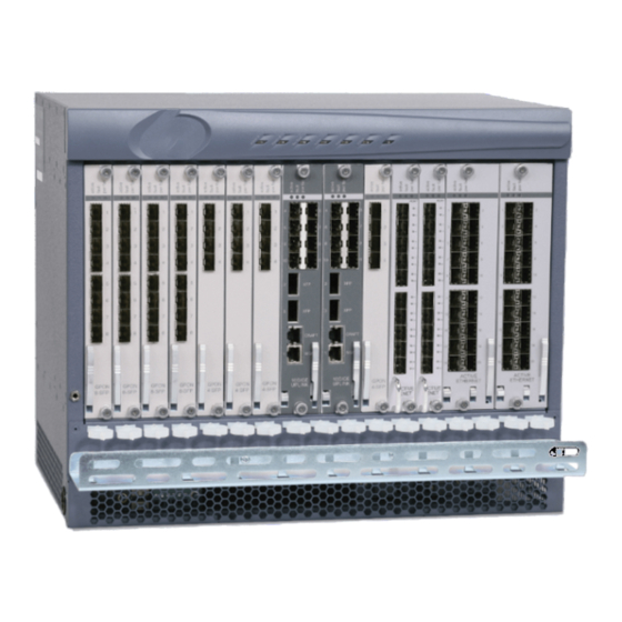
The 8U 19-inch and 23-inch chassis and the 3U chassis are functionally equivalent, the only difference is the number of slots supported. You can install the uplink cards, that provide the primary control and management functions for the MXK system, in a redundant pair to provide card-level redundancy. Figure 4 shows the 19”... - Page 20 3. For the MXK 819, power cables enter the device at the lower right front of the unit. Power for the MXK 823 is provided on both the front of the chassis and the rear of the chassis. Both power supplies are supplied by dual –48V DC input power.
- Page 21 MXK hardware overview Figure 4: MXK 19” chassis with 14 line cards and two uplink cards CRAFT CRAFT CRAFT CRAFT MGMT MGMT MGMT MGMT 10GIGE 10GIGE 10GIGE 10GIGE UPLINK UPLINK UPLINK UPLINK ACTIVE ACTIVE ACTIVE ACTIVE ETHERNET ETHERNET ETHERNET ETHERNET...
-
Page 22: Mxk 319 Chassis
MXK 319 chassis The MXK 319 chassis is a 19 inch wide and 3U high unit with 7 line card slots and 2 uplink card slots. The MXK 3U chassis also has a removable fan controller with six fans and alarm LEDs. -
Page 23: Add, Change Or Delete Card Profiles
Reset cards The resethold and resetrelease commands are available to place a card on hold in the system configuration, while the card is still in the MXK chassis. These commands may be used for diagnostic requirements when a card configuration should be placed on ‘hold’ while the physical card remains in the chassis. -
Page 24: Small Form Factor Pluggables
Chapter 15, Small Form Factor Pluggable (SFP) Connectors in the MXK Configuration Guide. MXK backplane The MXK has a non-blocking architecture with a high-speed backplane. Each line card on the MXK had a dedicated backplane trace to each of the uplink cards. MxK Hardware Installation Guide... -
Page 25: Install The Mxk
Compliance and certifications, page 35 Installation overview Before preparing to install the MXK, it is helpful to review this overview of MXK installation as it will take you from removing the chassis from the box through installing and verifying uplink and line cards. After completing MXK installation, refer to the MXK Configuration Guide for how to configure the software that runs the MXK. - Page 26 Chapter 3, System Cables and Connectors, on page 55 Communication cables should be at least two inches away from power lines. If the MXK is installed in an inside plant, the cables must be shielded and grounded at both ends.
-
Page 27: General Safety Precautions
Caution: Current limiting protectors The MXK is intended to be protected by 3-mil carbon blocks and current limiting protectors with a continuous carry current rating of 350 milliamperes. The current limiting protectors must be applied on the equipment side of the voltage limiting protector. -
Page 28: Prevent Electrostatic Damage
• The MXK system chassis requires a dedicated ground connection to the building ground. If more than one MXK chassis is to be installed on a rack, each one requires its own direct connection to the building ground. •... -
Page 29: Power Supply Safety Information
The system ships with mounting brackets. To avoid overloading the mounting brackets, and damaging the system, do not use the MXK chassis to support other equipment after it is mounted in the rack. Connect the system to the power supply circuit as described in this document. -
Page 30: Environmental Specifications
Altitude Operating altitude: Up to 13,123 ft. (4,000 m) Airflow MXK 819 and MXK 823: Bottom front to top rear. MXK 319: Right side to left side (facing front of chassis) Figure Figure 8 Figure 9 show the MXK chassis dimensions. - Page 31 Pre-installation preparation Figure 7: MXK 819 chassis dimensions Figure 8: MXK 823 chassis dimensions MXK Hardware Installation Guide...
-
Page 32: Power Requirements And Specifications
Chassis power consumption, page 33 Separate A and B power feeds allow two individual –48V DC power sources to be connected to the MXK system. The Return (+) terminals are common. For the 19 inch and 23 inch MXK chassis, the power wiring is field-terminated inside the lower front of the chassis. -
Page 33: Power Specifications
AWG 10 (5.27 mm ) maximum Listed circuit breaker or fuse 35 A maximum for MXK 819 and MXK 823 20 A maximum for MXK 319 A listed circuit breaker or fuse must be installed from a central DC power source and wired in accordance with NEC, ANSI/NFPA 70 and Canadian electrical code, Part 1, C22.1. -
Page 34: Grounding And Isolation
Install the MXK Grounding and isolation The MXK system cards and subassemblies use an integrated frame and logic ground system as follows: • The MXK system chassis and logic ground are bonded. • The two-wire power supply feed is not connected to the chassis. -
Page 35: Compliance And Certifications
EMC immunity CE EN55024 CE EN 50082 Network FCC Part 68 Install the MXK This section provides the information and procedures to install the MXK. • Unpack the system, page 35 • Install mounting brackets, page 36 • Mount the chassis in a rack, page 36 •... -
Page 36: Install Mounting Brackets
This section describes how to install mounting brackets on the MXK. Installing the mounting brackets onto the MXK system chassis The MXK mounting brackets are designed for use in a 19-inch or 23-inch rack. Use the following procedure to install the mounting brackets onto the system chassis: Carefully place the system chassis right side up and facing forward on a clean, flat, sturdy work surface. - Page 37 Figure 10: Installing the MXK in a rack Mounting the MXK 319 system chassis in a rack The system chassis can be mounted in a 19-inch rack that is connected to an earth ground. Use the following procedure to mount the system chassis in a rack: Choose a rack position for the system chassis.
-
Page 38: Install Cards
Caution: Use caution when inserting and removing the ADSL2+ cards to and from the MXK chassis. Be careful not to damage the caps on the board. MXK Hardware Installation Guide... - Page 39 Install the MXK Installing a slot card in the MXK chassis Note: You must install the uplink cards in middle slots, a and b. Put on an antistatic wrist strap that touches the skin. Make sure it is properly grounded to the ESD jack on the front of the unit.
- Page 40 Install the MXK Installing a slot card in the MXK 319 chassis Put on an antistatic wrist strap that touches the skin. Make sure it is properly grounded to the ESD jack on the front of the unit. Carefully remove the card from its antistatic packaging.
-
Page 41: Connect Power And Ground The Chassis
Model 3710 or similar meter to do this. Zhone recommends that the impedance be 5 ohms or less for proper equipment operation. If the ground path connected to the MXK has an impedance of more than 5 ohms, make improvements to the grounding system before installing the MXK equipment. -
Page 42: Connect Power To The Front Of The Mxk And Ground The Chassis
Should be hard wired to the main ground reference. Connect power to the front of the MXK and ground the chassis Power on the MXK 819 is located at the front of the chassis, see Figure MXK Hardware Installation Guide... - Page 43 Install the MXK Power on the MXK 823 is located on both the front of the chassis and the rear of the chassis. For the procedure on connecting the wiring between the MXK terminal block and the power supplies in the rear of the MXK 823 chassis, see...
- Page 44 Note: Some MXK terminal blocks have a quarter-turn screw. For these units, turn the screw 1/4 turn counterclockwise to loosen. Note: If the MXK is installed so that the thread hole on the side of the unit is inaccessible, thread the power supply and grounding...
- Page 45 16 Secure the hex bolts to the chassis. Note: For the # 8-32 ground stud and hex nuts the recommended torque is 12 to 16 in/lbs. 17 Connect the ground cable(s) routed in Step 13 and tighten the bolt. MXK Hardware Installation Guide...
- Page 46 12 to 16 in/lbs. Figure 18: Securing the terminal block and grounding the chassis Note: Some MXK terminal blocks have a quarter-turn screw. For these units, turn the screw 1/4 turn clockwise to tighten. 18 Reinstall the air filter (Figure 19).
-
Page 47: Connect Power To The Rear Of The Mxk 823 And Ground The Chassis
Connect power to the rear of the MXK 823 and ground the chassis Power on the MXK 823 chassis is located on both the front of the chassis and the rear of the chassis. This section describes connecting power to the rear of the chassis. - Page 48 Connecting power to the rear of the MXK 823 and grounding the chassis Use the following procedure to connect the wiring between the MXK terminal block and the power supplies in the rear of the MXK chassis. Remove the plastic safety cover (Figure 21).
- Page 49 Note: For the #8-32 ground stud and hex nuts the recommended torque is 12 to 16 in/lbs. Figure 24: Connect ground wire R T N -4 8 V D C The system is now ready to run power. Flip the on/off switch to on (Figure 25). MXK Hardware Installation Guide...
-
Page 50: Connect Power To The Mxk 319 And Ground The Chassis
On the rear of the MXK 319 chassis, remove the eight screws which attach the clear protective cover. The MXK 319 chassis will accept dual redundant power feeds — A & B. Loosen the wire clamp screws. They may be tight so use a screwdriver with a large diameter handle. - Page 51 B wires through the lower chassis openings and connect them to the lower (B) power terminals. Tighten the wire clamp screws. Tighten the wire clamp screws using a suitable torque driver to 8 ± 1 inch-lbs (0.9 ± 0.1 N·m). Do not overtighten. MXK Hardware Installation Guide...
-
Page 52: Verifying Proper Grounding Between The Chassis And The Rack
Using 10 AWG wire, secure the grounding lug to the chassis and the other end to a single point building ground. Tighten the nut using a suitable torque driver to 12 ± 1 inch-lbs (1.3 ± 0.1 N·m). Figure 26: Grounding the MXK 319 To verify proper grounding, please see Verifying proper grounding... - Page 53 Install the MXK The impedance should be less than 1 ohm. Test the impedance from the MALC chassis (point 3 in the graphic) to the grounding rack. The impedance must be less than 0.25 ohms. MXK Hardware Installation Guide...
- Page 54 Install the MXK MXK Hardware Installation Guide...
-
Page 55: Chapter 3 System Cables And Connectors
If you intend to install cable covers, the maximum height of the connector head and cable should be two inches. If the MXK is going to be installed in an inside plant, the cables must be shielded and grounded at both ends. -
Page 56: Cable Descriptions
26 AWG (0.4 mm) MXK alarm cable and contacts guidelines The MXK 819 and MXK 823 chassis alarms are located in the lower left of the chassis, behind the bezel. See Figure Figure 27: MXK chassis alarms When alarms are present, the connections are as follows: •... - Page 57 Major/minor alarm present closed open The specifications and requirements for the MXK chassis alarm cable and alarm relay contacts are as follows: • The alarm cable must be rated at VW-1 or higher. To comply with Part 15 of FCC regulations, all cables to DB connectors must be foiled with braided shielding.
- Page 58 Internal BITS clock fault Minor (if fallback to line clocking is provisioned, or if the clock source is currently provisioned as secondary source) Table 14: TAC alarms Event Type of alarm BITS clock Up/Down (only if Minor provisioned active) MXK Hardware Installation Guide...
-
Page 59: Fiber Optic Maintenance And Optical Connections
Report optical fiber breakage, page 62 Laser radiation Zhone equipment and associated optical test sets use laser sources that emit light energy into fiber cables. This energy is within the red (visible) and infrared (invisible) regions of the electromagnetic spectrum. -
Page 60: Handle Optical Fibers
WARNING! Older APC connectors may not use the standard eight degree angle and this difference could also result in an air gap condition. Standard connector coding: Blue: UPC Green: APC MXK Hardware Installation Guide... -
Page 61: Select Cleaning Materials
Fiber optic maintenance and optical connections Select cleaning materials Materials used for cleaning Zhone Technologies equipment should be high quality and suitable for the purpose. • Disconnect the cable end to be cleaned. • Using inert dusting gas, blow accumulated dust and debris off the cylindrical and end-face surfaces of the connector. -
Page 62: Report Optical Fiber Breakage
Notify both central-office and field-repair personnel of the problem. Identify to central-office personnel what fibers are damaged. Power off all laser sources related to the damaged fibers (whether located at the central office, subscriber premises, or remote location). MXK Hardware Installation Guide... -
Page 63: Mxk Hardware Maintenance
• Replacing the fan tray for the MXK 319 chassis, page 72 Read the LEDs The MXK 819 and MXK 823 system LEDs are located on the front bezel (see Figure 28 on page 63). Figure 28: MXK 819 and MXK 823 LEDs... -
Page 64: Chapter 4 Mxk Hardware Maintenance
MXK Hardware Maintenance Table 15: MXK system LED descriptions Description Power A (green) ON: battery “A” voltage is within tolerance. Bat OK A (green) OFF: battery “A” is not operational. Power B (green) ON: battery “B” voltage is within tolerance. -
Page 65: Install A Slot Card
Be sure to store the cards in areas that are free from excessive humidity and temperatures. Caution: The MXK system slot cards are susceptible to electrostatic discharge (ESD). ESD can cause component failure and degraded system performance. -
Page 66: Remove A Slot Card
Figure 29: Installing slot cards in the MXK Remove a slot card This section describes how to remove a slot card from the MXK chassis. Removing a slot card from the MXK chassis Put on an antistatic wrist strap that touches the skin. Make sure it is properly grounded to the ESD jack on the front of the unit. -
Page 67: Replace Running Redundant Uplink Cards
Uplinks a:*MXK TWO TENGIGE EIGHT GIGE (RUNNING) b: MXK TWO TENGIGE EIGHT GIGE (RUNNING) Cards 1: MXK 20 ACT ETH (RUNNING) 10: MXK 8 PORT GPON (RUNNING) Identify the active uplink card by one of these two methods: Look the Active LED on the uplink card faceplate. -
Page 68: Clean And Replace The Air Filter
Tighten the top and bottom screws to seat the uplink card in the backplane. Clean and replace the air filter Zhone recommends you clean or replace the MXK air filter every 3 to 6 months. Cleaning the air filter Before cleaning the air filter, visually inspect it for damage. If the filter is damaged, replace it. - Page 69 Replacing the air filter requires you to temporarily remove the cable management bracket (if installed). Before performing this procedure, make sure the MXK connectors are securely fastened. The MXK is designed so that the air filter can be removed without disturbing any of the cables.
-
Page 70: Replacing The Fan Tray For The 8U Chassis
Figure 32: Replacing the air filter Replacing the fan tray for the 8U chassis Remove the fan tray from the MXK and reinsert promptly after replacing a fan to ensure proper cooling to the MXK unit. Removing the fan tray Loosen and remove screws at either end of the upper activity lights facing. - Page 71 MXK chassis power connector. Securely seat the fan tray to ensure proper cooling to the MXK unit. Reinsert screws on either end of the upper activity lights facing and gently tighten.
-
Page 72: Replacing The Fan Tray For The Mxk 319 Chassis
MXK Hardware Maintenance Replacing the fan tray for the MXK 319 chassis There are six fans in the MXK 319 fan tray. The loss of any single fan should not cause the system to overheat. However, the fan tray should be replaced promptly to avoid overheating in the event of a second fan failure. - Page 73 Replacing the fan tray for the MXK 319 chassis Inserting the fan tray for the MXK 319 chassis Holding the handle on the fan tray, slide the tray into the chassis The fan tray snaps into place when it is fully seated.
- Page 74 MXK Hardware Maintenance MXK Hardware Installation Guide...
-
Page 75: Index
NDEX unpacking 35 weight 30 weight distribution 29 Active Ethernet card chassis alarms 56 10-port 15 chassis dimensions 30 20-port 15 circuit breaker, specifications 33 air filter, replacing 69 cleaning components 59 airflow, system requirements for 29 common return 32 alarm cables and contacts compliance, specifications supported 35 guidelines 57... - Page 76 36 MXK-ADSL2+-SPLTR900-BCM-48A-2S 13 rack installation 36, 37 MXK-AEX20-FE/GE 13 removing slot cards 66 MXK-AEX20-FE/GE-2S 13 removing uplink cards 67 MXK-EFM-SHDSL-24 NTP 14 unpacking the system 35 MXK-EFM-SHDSL-24-NTWC 14 installation precautions 29 MXK-GPONX4-IO 13 airflow 29 MXK-GPONX8-IO 13 cables and connectors 29...
- Page 77 system input power 32 rack installation chassis 36, 37 temperature, maximum 29 procedure 36, 37 tools for installation 34 rated current 33 rated power 33 redundancy LEDs 64 removing slot cards, procedure for 66 ventilation, requirements for 29 removing uplink cards, procedure for 67 resethold command 23 resetrelease command 23 safety...
- Page 78 Index MALC Hardware Installation Guide...