Table of Contents
Advertisement
Advertisement
Table of Contents

Summary of Contents for Siemens TPS3 01
- Page 1 TPS3 Internal Manual Surge Protective Device User Manual - CANADA...
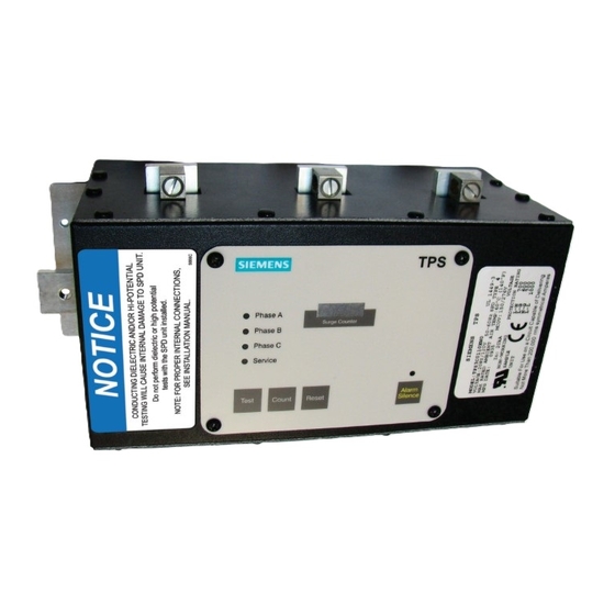
- Page 2 V DANGER NOTICE Hazardous voltage. CONDUCTING DIELECTRIC AND/OR Will cause death or serious injury. HI-POTENTIAL TESTING WILL CAUSE Keep Out. INTERNAL DAMAGE TO TPS3 UNIT. Qualified personnel only. Do not perform dielectric or high potential Disconnect and lock off all power before tests with the TPS3 unit installed. working on this equipment. •...
-
Page 3: Table Of Contents
TPS3 01 Installation Instructions for: Lighting Panelboards Original P1, P2, P3 ....5 Internal Phase Labeling Connections ..........................5 TPS3 01 Installation Instructions for: 400/600 Amp S1/S2 & All SE Panels ......6 Internal Phase Labeling Connections ..........................6 TPS3 02 Installation Instructions for: Lighting Panelboards Revised P1 ....... 7 Internal Phase Labeling Connections ..........................7... -
Page 4: Introduction
(a) Is trained and authorized to energize, deenergize, clear, component thereof. ground and tag circuits and equipment in accordance with established safety practices. The sales contract contains the entire obligation of Siemens. This (b) Is trained in the proper care and use of personal protective instruction manual shall not become part of or modify any prior existing equipment (PPE) such as rubber gloves, hard hat, safety agreement, commitment or relationship. glasses or face shields, flash clothing, etc. in accordance with established safety practices. -
Page 5: Industry Standards Changes - 2009
Industry Standards Changes - 2009 Siemens TPS3 SPDs have the following Type designations UL 1449 Third Edition and 2008 NEC® Article 285 generated substantial Table 1: Type Designations changes. SIEMENS TPS3 SERIES TYPE RATING • The term TVSS changed to SPD TPS3 01 & L1 Type 1 Component Assembly • Types 1, 2, 3 & 4 SPDs are created • UL 1449 clamping voltage performance testing changed from TPS3 02 & L2 Type 1 Component Assembly 500A to 3,000A TPS3 05 & L5 Type 1 • UL 1449 added new Nominal Discharge Current testing (I nominal, TPS3 06 & L6 Type 1 Component Assembly or I ), which consists of more rigorous duty-cycle testing The SPD Type category is important to understand before installing For further information, please review latest editions of NEC® Art. 285,... -
Page 6: Table 2: Model Number Decoder
Table 2: Model Number Decoder TPS3 Catalog # Voltage TPS Series Surge Option Default Code Description Current Codes Rating - Example: TPS3C0120X0 = SPD for a 208/120V panelboard with a surge current capacity of 200 kA per phase and a surge counter option TPS SERIES DESCRIPTION TPS3 01 SPD for “Original P1”, P2, P3 Lighting and Power Distribution Panelboards, MCC and Busway TPS3 L1 10 Mode SPD for SPD for “Original P1”, P2, P3 Lighting and Power Distribution Panelboards, MCC and Busway TPS3 02 SPD for “Revised P1” Lighting Panelboard TPS3 L2 10 mode SPD for “Revised P1” lighting Panelboard TPS3 05 SPD for P4 & P5 Panelboards and Distribution Switchboards TPS3 L5 10 Mode SPD for P4 & P5 Panelboards and Distribution Switchboards TPS3 06 SPD for SB1, SB2, SB3, Type RCS Switchboards, MCC and Busway TPS3 L6 10 Mode SPD for SB1, SB2, SB3, Type RCS Switchboards, MCC and Busway VOLTAGE CODES TPS3 01 TPS3 L1 TPS3 02 TPS3 L2 TPS3 05... -
Page 7: General Information
General Information Audible Noise The SPD’s background noise is negligible which permits installation This device features internal overcurrent and overtemperature within the equipment in almost any room. protection that will disconnect affected surge suppression components at the end of their useful life, but will maintain power to the load – now Dead Front Modification Instruction Changes for P1 SPD unprotected. If this situation is undesirable for the application, follow these instructions for servicing or replacing the device. The TPS3 unit requires a dead front opening to display its face plate. Remove any installed cover from a dead front opening at the Service of this unit consists of replacing the internal module and/or TPS3 module location. If there is no dead front opening, follow the display assembly. instructions in Fig. 2 to create an opening by removing a knockout plate. -
Page 8: Tps3 01 Installation Instructions For: Lighting Panelboards Original P1, P2, P3
Determine the mounting location of the TPS3 in the distribution follow: equipment. If it is to be mounted in the top of the distribution equipment or relocated after installation, internal phase labeling The following instructions are for the installation of the Siemens TPS3 connections must be changed to ensure proper diagnostic board indication. These modifications should be made prior to installation. 01 and L1 SPD modules in Siemens Original P1, P2 and P3 lighting If the TPS3 module is field installed in the bottom, or if it is mounted in panelboards. Be aware of differences between the Revised P1 and... -
Page 9: Tps3 01 Installation Instructions For: 400/600 Amp S1/S2 & All Se Panels
Figure 4: 400/600 Amp S1/S2 and all SE Panels - Lock off all power supplying this equipment before working on it. TPS3 01 Unit with the NK Accessory Kit Remove the trim and dead front. Install the mounting bracket (Item 5) to the base rail as shown in Figure 3 using two (2) of the #10 thread forming screws (item 3). -
Page 10: Tps3 02 Installation Instructions For: Lighting Panelboards Revised P1
If model number includes W option suffix, additional instructions follow: 400A use inner holes on outer phases and center hole on center phase. Machine screws thread into the Connector mounted below the buss The following instructions are for the installation of the Siemens TPS3 bar. Do not tighten at this time. 02 and L2 SPD modules in Siemens Revised P1 lighting panelboards. Be aware o f d ifferences b etween t he R evised P 1 a nd O riginal P 1 p anelboards. Position the TPS3 unit (item 1) on the panel base rail so that the TPS3 SPDs for Original P1 and Revised P1 are not interchangeable. Original P1... -
Page 11: Figure 6: Spd & Neutral Riser Connection Details For Revised P1 Panels
If panel is equipped with a neutral conductor: • (250A only, not required for 400A) Install Neutral Riser (item 12) per Figure 5. Use two (2) 5/16”-18 Slotted Hex Thread Forming • (250A only, not required for 400A) Install Neutral Riser Support Screws (item 13) to connect one end of Neutral Riser to existing (item 10) per Figure 5 using #10-16 x ½” Type BT Slotted Hex Neutral Bussing provided with panel and other end of Neutral Thread Forming Screw (item 11). Do not tighten at this time. Riser to Neutral Riser Support. • Attach Neutral Jumper (item 8) to top side of TPS3 (item 1) neutral Torque all connections to the values as specified on the installation tab with ¼-20 x 5/8” machine screw (item 4) and ¼”-20 SEMS nut and maintenance instruction label affixed to the rear of the dead front. (item 9). Do not tighten at this time. (400A panels only: rotate neutral jumper so single-hole end lands on SPD neutral to ensure Replace trim and deadfront. proper height and fitment. Use (1) 5/16” - 18 slotted hex thread forming screw (item 13) to connect other end of neutral jumper 400 Amp Panels to existing neutral bussing.) Figure 6: SPD & Neutral Riser Connection Details for Revised P1 Panels Buss Connector Detail NOTE ORIENTATION OF NEUTRAL CONNECTOR 250 Amp 42 Circuit... -
Page 12: Tps3 05 And Tps3 06 Module Replacement Instructions
Qualified personnel only. Do not perform dielectric or high potential Disconnect and lock off all power before working on this equipment. tests with the TPS3 unit installed. TPS3 05 and TPS3 06 Module Replacement Instructions The following instructions are for the replacement of Siemens TPS3 The following instructions are for the replacement of Siemens TPS3 SPD module in Siemens TPS3 05 unit. SPD module in Siemens TPS3 06 unit. Figure 6: P4, P5 & Front Connected Distribution Switchboards Figure 7: Service Section Switchboards & Low Voltage Switchgear NOTE: TPS3 05 unit may be replaced only if supplied with an internal NOTE: TPS3 06 unit may be replaced only if supplied with an internal disconnect. -
Page 13: Tps3 01 And Tps3 06 Module Installation Instructions: Mcc
The following instructions are for the replacement of Siemens TPS3 SPD module in a TIASTAR MCC. c) Any attachment-plug receptacles in the vicinity of the filter are to be of a grounding type, and the grounding conductors serving these This unit is intended for custom factory installation during MCC receptacles are to be connected to earth ground at the service equipment manufacture. Unit must be removed from the MCC or withdrawn or other acceptable building earth ground such as the building frame to the TEST position. Familiarize with the TPS and MCC mounting... -
Page 14: Operation
Test: Tests red Service LED and Audible Alarm, and changes state of Prior to installing SPD, install, rotate and tighten box lug terminals to the top of the SPD phase connection tabs, pointing toward breaker location. Dry Contacts. Alarm Silence: Turns Audible Alarm off. (Alarm is deactivated when Mount the SPD using supplied hardware, per previous instructions. the Silence LED is illuminated.) Connect the neutral connection by wire or bracket as appropriate. Install conductors: Identify each panelboard buss as Phase A, B and C. Surge Counter Count: (if equipped) Increments optional surge counter When the SPD is installed, the SPD’s Phase Tabs will have near proximity by one (+1). above energized panelboard busses. The SPD’s phase connections must correspond to buss phases. Connect conductors from the SPD’s Phase Surge Counter Reset: (if equipped) Resets optional surge counter to Tabs to corresponding circuit breaker connections. For example, when zero (0). energized, the SPD Phase Tab for Phase A must be located above the panelboard buss for Phase A. The SPD Phase Tab for Phase B must be located above the panelboard buss for Phase B. The SPD Phase Tab for Phase C must be located above the panelboard buss for Phase C. Conductors must be as short and straight as possible. Use gentle radius on any bends. Do not kink wires. Prevent wires from encroaching breaker locations. -
Page 15: Maintenance
Sustained Overvoltages, as well as voltage surge protection. The large variations in operating conditions ungrounded generators, and/or usual load transfer systems. encountered by units in the field make it difficult to set a fixed maintenance interval, but inspections utilizing the built-in diagnostics Abnormal N-G Voltage Indicators should be performed at least on a weekly or monthly basis. This SPD include N-G voltage indicators. If the SPD detects excessive Corrective Maintenance (Repair) N-G voltage, the Red Service LED will blink and the Audible Alarm will cycle. This condition requires immediate attention as the SPD will fail. The Siemens TPS3 unit is designed for years of reliable, trouble-free Incorrectly bonded distribution systems damage SPDs. If the XO or N-G operation. Unfortunately, in an extreme case, you may experience an bonding jumper is not installed, the electrical system has no reference to alarm condition. In this event, no attempt should be made to repair the ground. It becomes an ungrounded system. Please see previous section TPS3 itself. There are no serviceable parts within the unit. Any SPD that regarding SPDs on ungrounded systems. Such systems are known to requires service should be appropriately removed from the electrical eventually produce abnormally high L-G voltages. SPDs will attempt distribution equipment, and replaced by a new SPD of the same model. - Page 16 Siemens Canada Limited 1577 North Service Road East European Authorized Representative Oakville, ON L6H 0H6 Obelis s.a. Boulevard Général Wahis 53 SPD Hotline: 888.333.3545 1030 Brussels, BELGIUM Tel: +(32) 2. 732.59.54 info@purgethesurge.ca Fax: +(32) 2. 732.60.03 E-Mail: mail@obelis.net 2.16.15.lh #8225...