Table of Contents
Advertisement
Quick Links
Advertisement
Table of Contents

Related Manuals for Asus Z11PR-D16


Summary of Contents for Asus Z11PR-D16
- Page 1 Z11PR-D16 User Guide...
- Page 2 Product warranty or service will not be extended if: (1) the product is repaired, modified or altered, unless such repair, modification of alteration is authorized in writing by ASUS; or (2) the serial number of the product is defaced or missing.
-
Page 3: Table Of Contents
Contents Notices ........................vii Safety information ....................viii Z11PR-D16 specifications summary ............... xii Chapter 1: Product Introduction Welcome! ....................1-2 Package contents ..................1-2 Serial number label ..................1-3 Special features..................1-3 1.4.1 Product highlights................ 1-3 1.4.2 Innovative ASUS features ............1-4 Chapter 2: Hardware Information Before you proceed ................... - Page 4 3.2.2 Using the dual function power switch .......... 3-3 Chapter 4: BIOS Setup Managing and updating your BIOS ............4-2 4.1.1 ASUS CrashFree BIOS 3 utility........... 4-2 4.1.2 ASUS EZ Flash Utility ..............4-3 4.1.3 BUPDATER utility ............... 4-4 BIOS setup program .................. 4-6 4.2.1...
- Page 5 Contents 4.4.11 NVMe Configuration ..............4-23 4.4.12 USB Configuration ..............4-23 4.4.13 iSCSI Configuration..............4-24 4.4.14 Intel(R) RSTe RAID Controller ..........4-24 Platform Configuration menu ..............4-24 4.5.1 PCH Configuration ..............4-25 4.5.2 Miscellaneous Configuration ............. 4-27 4.5.3 Server ME Configuration ............4-27 4.5.4 Runtime Error Logging Support ..........
- Page 6 VGA driver installation ................6-10 ® Installing the Intel I350-AM2 Gigabit Adapters driver ......6-12 ® Intel Rapid Storage Technology enterprise installation ..... 6-14 Appendix Z11PR-D16 block diagram ..................A-2 Simplified EU Declaration of Conformity .............. A-3 ASUS contact information ..................A-4...
-
Page 7: Notices
Radio Interference Regulations of the Canadian Department of Communications. This class B digital apparatus complies with Canadian ICES-003. REACH Complying with the REACH (Registration, Evaluation, Authorization, and Restriction of Chemicals) regulatory framework, we publish the chemical substances in our products at ASUS REACH website at http://csr.asus.com/english/REACH.htm. -
Page 8: Safety Information
Safety information Electrical safety • To prevent electrical shock hazard, disconnect the power cable from the electrical outlet before relocating the system. • When adding or removing devices to or from the system, ensure that the power cables for the devices are unplugged before the signal cables are connected. If possible, disconnect all power cables from the existing system before you add a device. - Page 9 If you require assistance please call ASUS Customer Service 1300 2787 88 or visit us at https://www.asus.com/support...
-
Page 10: About This Guide
Refer to the following sources for additional information and for product and software updates. ASUS Control Center (ACC) user guide This manual tells how to set up and use the proprietary ASUS server management utility. Visit asuscontrolcenter.asus.com for more information. -
Page 11: Conventions Used In This Guide
Conventions used in this guide To ensure that you perform certain tasks properly, take note of the following symbols used throughout this manual. DANGER/WARNING: Information to prevent injury to yourself when trying to complete a task. CAUTION: Information to prevent damage to the components when trying to complete a task. -
Page 12: Z11Pr-D16 Specifications Summary
1.2V Capacity Maximum up to 2048GB DDR4 2666/2400/2133 RDIMM/LR-DIMM/LR-DIMM 3DS Memory Memory Type * Refer to www.asus.com for the latest memory AVL update. 4GB, 8GB, 16GB, 32GB (RDIMM) 32GB, 64GB (LRDIMM) Memory Size 64GB, 128GB (LRDIMM 3DS) Total PCI/ PCI-X... - Page 13 Operating temperature: 10°C ~ 35°C Environment Non operating temperature: -40°C ~ 70°C Non operating humidity: 20% ~ 90% (Non condensing) * Specifications are subject to change without notice. ** Refer to www.asus.com for the complete list of supported PIKE cards. xiii...
-
Page 15: Chapter 1: Product Introduction
Chapter 1: Product Introduction Product Introduction This chapter describes the motherboard features and the new technologies it supports. -
Page 16: Welcome
Z11PR-D16 motherboard! The motherboard delivers a host of new features and latest technologies, making it another standout in the long line of ASUS quality motherboards! Before you start installing the motherboard and hardware devices on it, check the items in your package with the list below. -
Page 17: Serial Number Label
Serial number label Before requesting support from the ASUS Technical Support team, you must take note of the motherboard's serial number containing 12 characters xxS2xxxxxxxx shown in the figure below. With the correct serial number of the product, ASUS Technical Support team members can then offer a quicker and satisfying solution to your problems. -
Page 18: Innovative Asus Features
1.4.2 Innovative ASUS features ASUS Fan Speed control technology The ASUS Fan Speed control technology smartly adjusts the fan speeds according to the system loading to ensure a quiet, cool, and efficient operation. Chapter 1: Product Introduction... -
Page 19: Chapter 2: Hardware Information
Chapter 2: Hardware Information Hardware Information This chapter lists the hardware setup procedures that you have to perform when installing system components. It includes description of the jumpers and connectors on the motherboard. -
Page 20: Before You Proceed
Before you proceed Take note of the following precautions before you install any motherboard component or change any motherboard settings. • Unplug the power cord from the wall socket before touching any component. • Use a grounded wrist strap or touch a safely grounded object or a metal object, such as the power supply case, before handling components to avoid damaging them due to static electricity. • Hold components by the edges to avoid touching the ICs on them. • Whenever you uninstall any component, place it on a grounded antistatic pad or in the bag that came with the component. • Before you install or remove any component, ensure that the power supply is switched off or the power cord is detached from the power supply. -
Page 21: Motherboard Overview
Screw holes Place nine (9) screws into the holes indicated by circles to secure the motherboard to the chassis. DO NOT overtighten the screws! Doing so can damage the motherboard. Place this side towards the rear of the chassis Z11PR-D16... -
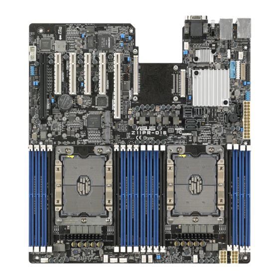
Page 22: Motherboard Layout
2.2.3 Motherboard layout Chapter 2: Hardware Information... -
Page 23: Layout Contents
2-34 Thermal sensor cable connector (3-pin TR1) 2-38 Serial port connector (10-1 pin COM1) 2-29 Micro SD card slot (MSD1) 2-35 DMLAN setting (3-pin DM_IP_SEL1) 2-19 Baseboard Management Controller setting (3-pin BMC_EN1) 2-16 DDR4 thermal event setting (3-pin DIMMTRIP1; DIMMTRIP2) 2-17 VGA controller setting (3-pin VGA_SW1) 2-15 LANNCSI setting (3-pin LANNCSI_SEL1) 2-18 LAN controller setting (3-pin LAN_SW1, LAN_SW2) 2-15 VGA connector (16-pin VGA_HDR1) 2-33 USB 3.0 connector (20-1 pin USB3_34) 2-27 VROC KEY connector (4-pin VROC_KEY1) 2-36 LAN Activity LED connector (5-1 pin LAN34_LED1) 2-28 System panel connector (20-1 pin PANEL1) 2-31 Serial ATA connectors (7-pin SSATA1-3) 2-26 Mini-SAS HD connector (ISATA1-2) 2-26 Mezzanine PCIE card connectors (MEZZPCIE1-2) 2-35 OCP LAN Activity LED connector (4-1 pin OCP_LED1) 2-37 M.2 (NGFF) card connectors (NGFF1-2) 2-36 Z11PR-D16... -
Page 24: Central Processing Unit (Cpu)
Central Processing Unit (CPU) The motherboard comes with a surface mount LGA 2011 R3 socket designed for the Intel ® Xeon E5-2600 v3 processor family. • Upon purchase of the motherboard, ensure that the PnP cap is on the socket and the socket contacts are not bent. Contact your retailer immediately if the PnP cap is missing, or if you see any damage to the PnP cap/socket contacts/motherboard components. ASUS will shoulder the cost of repair only if the damage is shipment/ transit-related. • Keep the cap after installing the motherboard. ASUS will process Return Merchandise Authorization (RMA) requests only if the motherboard comes with the cap on the LGA 2011 R3 socket. • The product warranty does not cover damage to the socket contacts resulting from incorrect CPU installation/removal, or misplacement/loss/incorrect removal of the PnP cap. 2.3.1 Installing the CPU To install a CPU: Locate the CPU socket on the motherboard. 2. Remove the PnP caps from the CPU sockets. Chapter 2: Hardware Information... - Page 25 Carrier until it clicks firmly into place (B), and then install the CPU Carrier into the CPU Carrier heatsink until it clicks firmly in place (C). Ensure that the triangle mark on the CPU matches the triangle mark on the CPU Carrier. Triangle mark Align the CPU and CPU Carrier in the correct orientation, and then place the heatsinks on top of the CPU sockets. The CPU and CPU Carrier fits in only one correct orientation. DO NOT force the CPU and CPU Carrier into the socket to prevent damaging the CPU pins on the socket. Twist each of the four screws with a screwdriver just enough to attach the heatsink to the motherboard. When the four screws are attached, tighten them one by one in a diagonal sequence to completely secure the heatsink. The heatsink screws are T30 models. A torque value of 12 inch-lbf is recommended. Z11PR-D16...
-
Page 26: System Memory
The motherboard comes with sixteen (16) Double Data Rate 4 (DDR4) Dual Inline Memory Modules (DIMM) sockets. The figure illustrates the location of the DDR4 DIMM sockets: 2.4.2 Memory Configurations You may install 4 GB, 8 GB, 16 GB, and 32 GB RDIMMs; 32 GB, and 64 GB LRDIMMs; and 64GB and 128GB LRDIMMs (3DS) into the DIMM sockets using the memory configurations in this section. • Refer to ASUS Server AVL for the updated list of compatible DIMMs. • Always install DIMMs with the same CAS latency. For optimum compatibility, it is recommended that you obtain memory modules from the same vendor. • Start installing the DIMMs in slot A1. Single CPU configuration (must be installed on CPU1) DIMM DIMM_C1 •... - Page 27 DIMM_E1 • • • DIMM_F1 • • DIMM_J1 • • • DIMM_H1 • • • • • • • • • • • DIMM_G1 DIMM_G2 • • DIMM_K2 DIMM_K1 • • • DIMM_L1 • • • DIMM_M1 • • Z11PR-D16...
-
Page 28: Installing A Dimm On A Single Clip Dimm Socket
2.4.3 Installing a DIMM on a single clip DIMM socket Ensure to unplug the power supply before adding or removing DIMMs or other system components. Failure to do so may cause severe damage to both the motherboard and the components. Unlock a DIMM socket by pressing the DIMM notch retaining clip outward. -
Page 29: Expansion Slots
Secure the card to the chassis with the screw you removed earlier. Replace the system cover. 2.5.2 Configuring an expansion card After installing the expansion card, configure it by adjusting the software settings. Turn on the system and change the necessary BIOS settings, if any. See Chapter 4 for information on BIOS setup. Assign an IRQ to the card. Refer to the table Standard Interrupt assignments in section Interrupt assignments for more information. Install the software drivers for the expansion card. When using PCI cards on shared slots, ensure that the drivers support “Share IRQ” or that the cards do not need IRQ assignments. Otherwise, conflicts may arise between the two PCI groups, making the system unstable and the card inoperable. Z11PR-D16 2-11... -
Page 30: Interrupt Assignments
2.5.3 Interrupt assignments Standard Interrupt assignments Priority Standard function System Timer Keyboard Controller Programmable Interrupt Communications Port (COM2) Communications Port (COM1) Floppy Disk Controller System CMOS/Real Time Clock ACPI Mode when used IRQ Holder for PCI Steering IRQ Holder for PCI Steering PS/2 Compatible Mouse Port Numeric Data Processor Primary IDE Channel Secondary IDE Channel * These IRQs are usually available for ISA or PCI devices. 2.5.4 PCI Express x16 slot (x16 link) The onboard PCIE6 provides one x16 Gen3 link to CPU1, and PCIE1 provides one x16 Gen3 link to CPU2. These slots support various server class high performance add-on cards. 2.5.5 PCI Express x8 slot (x8 link) The onboard PCIE2, PCIE3, PCIE4, and PCIE5 each provides one x8 Gen3 link to CPU2. - Page 31 No. (Slot location) Short description PCIE6 PCI-E x16 (x16 Gen3 link) PCIE5 PCI-E x8 (x8 Gen3 link) PCIE4 PCI-E x8 (x8 Gen3 link) PCIE3 PCI-E x8 (x8 Gen3 link) PCIE2 PCI-E x8 (x8 Gen3 link) PCIE1 PCI-E x16 (x16 Gen3 link) Z11PR-D16 2-13...
-
Page 32: Jumpers
Jumpers Clear RTC RAM (3-pin CLRTC1) This jumper allows you to clear the Real Time Clock (RTC) RAM in CMOS. You can clear the CMOS memory of date, time, and system setup parameters by erasing the CMOS RTC RAM data. The onboard button cell battery powers the RAM data in CMOS, which include system setup information such as system passwords. To erase the RTC RAM: Turn OFF the computer and unplug the power cord. Move the jumper cap from pins 1-2 (default) to pins 2-3. Keep the cap on pins 2-3 for about 5-10 seconds, then move the cap back to pins 1-2. Plug the power cord and turn ON the computer. Hold down the <Del> key during the boot process and enter BIOS setup to re- enter data. Except when clearing the RTC RAM, never remove the cap on CLRTC jumper default position. Removing the cap will cause system boot failure! If the steps above do not help, remove the onboard battery and move the jumper again to clear the CMOS RTC RAM data. After the CMOS clearance, reinstall the battery. Chapter 2: Hardware Information 2-14... - Page 33 VGA controller setting (3-pin VGA_SW1) This jumper allows you to enable or disable the onboard VGA controller. Set to pins 1–2 to activate the VGA feature. LAN controller setting (3-pin LAN_SW1, LAN_SW2) ® These jumpers allow you to enable or disable the onboard Intel I350-AM2 Gigabit LAN1/2 controller. Set to pins 1–2 to activate the Gigabit LAN feature. Z11PR-D16 2-15...
- Page 34 ME firmware force recovery setting (3-pin ME_RCVR1) ® This jumper allows you to force Intel Management Engine (ME) boot from recovery mode when ME becomes corrupted. Baseboard Management Controller setting (3-pin BMC_EN1) This jumper allows you to enable (default) or disable on-board BMC. Ensure to set this BMC jumper to enabled to avoid system fan control and hardware monitor error. Chapter 2: Hardware Information 2-16...
- Page 35 DDR4 thermal event setting (3-pin DIMMTRIP1; DIMMTRIP2) This jumper allows you to enable or disable DDR4 DIMM thermal sensing event pin. PCH_MFG1 setting (3-pin PCH_MFG1) This jumper allows you to update the BIOS ME block. Z11PR-D16 2-17...
- Page 36 Smart Ride Through (SmaRT) setting (3-pin SMART_PSU1) This jumper allows you to enable or disable the Smart Ride Through (SmaRT) function. This feature is enabled by default. Set to pins 2-3 to disable it. When enabled, SmaRT allows uninterrupted operation of the system during an AC loss event. LANNCSI setting (3-pin LANNCSI_SEL1) This jumper allows you to select which LAN NCSI to function. Chapter 2: Hardware Information 2-18...
- Page 37 DMLAN setting (3-pin DM_IP_SEL1) This jumper allows you to select the DMLAN setting. Set to pins 2-3 to force the DMLAN IP to static mode (IP=10.10.10.10, submask=255.255.255.0). Z11PR-D16 2-19...
-
Page 38: Internal Leds
Internal LEDs Standby Power LED (SBPWR1) The motherboard comes with a standby power LED. The green LED lights up to indicate that the system is ON, in sleep mode, or in soft-off mode. This is a reminder that you should shut down the system and unplug the power cable before removing or plugging in any motherboard component. The illustration below shows the location of the onboard LED. Location LED (LOCLED1) This onboard LED lights up when the Location button on the server is pressed or when triggered by a system management software. The Location LED helps visually locate and quickly identify the server in error on a server rack. - Page 39 Storage device activity LED (HDDLED1) This LED is for the storage devices connected to the onboard SATA, or SATA/SAS add-on card. The read or write activities of any device connected to the onboard SATA, or SATA/SAS add-on card causes the rear panel LED to light up. Message LED (MESLED1) This onboard LED lights up to orange when there is a BMC event log is generated. Z11PR-D16 2-21...
- Page 40 BMC LED (BMCLED1) The BMC LED blinks to indicate that the on-board BMC is functional. CATERR1 LED (CATERR1) The CATERR1 LED indicates that the system has experienced a fatal or catastrophic error and cannot continue to operate. Chapter 2: Hardware Information 2-22...
-
Page 41: Connectors
Q-Code LEDs. The Q-Code LED design provides you with a 2-digit error code that displays the system status. Refer to the Q-Code table for more details LAN port LED indications ACT/LINK LED SPEED LED ACT/LINK LED SPEED LED ACT/LINK LED SPEED LED Status Description Status Description No link 10 Mbps connection GREEN Linked ORANGE 100 Mbps connection BLINKING Data activity GREEN 1 Gbps connection Z11PR-D16 2-23... - Page 42 Q-Code table Action PHASE POST CODE TYPE DESCRIPTION Progress First post code(POWER_ON_POST_CODE) Progress Load BSP microcode(MICROCODE_POST_CODE) Progress Perform early platform initialization Security Phase Progress Set cache as ram for PEI phase(CACHE_ENABLED_POST_CODE) Progress Establish Stack Progress CPU Early init.(CPU_EARLY_INIT_POST_CODE) Progress PEI Core Entry Progress PEI cache as ram CPU initial Progress NB initialize before installed memory Progress SB initialize before installed memory MRC Progress MRC_INITIALIZATION_START MRC Progress MRC_CMD_PLOT_2D MRC Progress MRC_FAST_BOOT_PERMITTED MRC Progress MRC_RESTORE_NON_TRAINING MRC Progress...
- Page 43 Selection) phase Progress Reset system Progress USB hotplug Progress NVRAM clean up Progress NVRAM configuration reset Progress IDE, AHCI Init. Progress IDE, AHCI Init. Progress IDE, AHCI Init. Progress IDE, AHCI Init. FF~00 Progress Wait BMC ready(duration: 120 seconds). Progress BIOS Setup Utility password verify Progress BIOS Setup Utility start Progress BIOS Setup Utility input wait Progress Ready to boot event Progress Legacy boot event Progress APIC mode Operating system phase Progress PIC mode Z11PR-D16 2-25...
-
Page 44: Internal Connectors
2.8.2 Internal connectors Serial ATA connectors (7-pin SSATA1-3) ® These connectors, controlled by Intel C621 chipset, are for the Serial ATA signal cables for Serial ATA hard disk drives (SATA 1 connector is used for the optical drive by default). Mini-SAS HD connector (ISATA1-2) This motherboard comes with mini Serial Attached SCSI (SAS) HD connectors, the storage technology that supports Serial ATA. Each connector supports up to four devices. Chapter 2: Hardware Information 2-26... - Page 45 USB 2.0 connector (10-1 pin USB78; USB56) This connector is for USB 2.0 ports. Connect the USB module cable to the connector, and then install the module to a slot opening at the back of the system chassis. The USB connectors comply with USB 2.0 specification that supports up to 480 Mbps connection speed. The USB port module is purchased separately. USB 3.0 connector (20-1 pin USB3_34) This connector allows you to connect a USB 3.0 module for additional USB 3.0 front or rear panel ports. With an installed USB 3.0 module, you can enjoy all the benefits of USB 3.0 including faster data transfer speeds of up to 5Gbps, faster charging time for USB-chargeable devices, optimized power efficiency, and backward compatibility with USB 2.0. Z11PR-D16 2-27...
- Page 46 CPU, front, and rear fan connectors (4-pin FRNT_FAN1-7; REAR_FAN1-2) The fan connectors support cooling fans of 0.8A–1.0A (12 W max.) or a total of 6.4 A–8.0 A (96 W max.) at +12V. Connect the fan cables to the fan connectors on the motherboard, making sure that the black wire of each cable matches the ground pin of the connector. DO NOT forget to connect the fan cables to the fan connectors. Insufficient air flow inside the system may damage the motherboard components. These are not jumpers! DO NOT place jumper caps on the fan connectors! LAN Activity LED connector (5-1 pin LAN34_LED1) These leads are for 10G LAN activity LEDs on the front panel. Connect the LAN LED cable to the backplane for LAN activity indication.
- Page 47 Serial port connector (10-1 pin COM1) This connector is for a serial (COM) port. Connect the serial port module cable to this connector, then install the module to a slot opening at the back of the system chassis. The COM module is purchased separately. TPM connector (20-1 pin TPM1) This connector supports a Trusted Platform Module (TPM) system, which can securely store keys, digital certificates, passwords, and data. A TPM system also helps enhance network security, protects digital identities, and ensures platform integrity. Z11PR-D16 2-29...
- Page 48 ATX power connectors (24-pin EATXPWR1; 8-pin EATX12V1; 8-pin EATX12V2) These connectors are for the ATX power supply plugs. The power supply plugs are designed to fit these connectors in only one orientation. Find the proper orientation and push down firmly until the connectors completely fit. • DO NOT forget to connect the 24-pin and the 8-pin power plugs; otherwise, the system will not boot up. • Use of a power supply unit (PSU) with a higher power output is recommended when configuring a system with more power-consuming devices. The system may become unstable or may not boot up if the power is inadequate. • This motherboard supports ATX2.0 PSU or later version. • Ensure that your PSU can provide at least the minimum power required by your system. Chapter 2: Hardware Information 2-30...
-
Page 49: System Panel Connector
Pressing the power switch for more than four seconds while the system is ON turns the system OFF. Reset button (2-pin RESET) This 2-pin connector is for the chassis-mounted reset button for system reboot without turning off the system power. Z11PR-D16 2-31... - Page 50 Auxiliary panel connector (20-2 pin AUX_PANEL1, 20-pin AUX_PANEL2) This connector is for additional front panel features including front panel SMB, locator LED and switch, chassis intrusion, and LAN LEDs. Front panel SMB (6-1 pin FPSMB) This 6-1 pin connector is for the front panel SMBus cable. LAN activity LED (2-pin LAN1_LED, LAN2_LED) This 2-pin connector is for the Gigabit LAN activity LEDs on the front panel. Locator LED (2-pin LOCATORLED1, 2-pin LOCATORLED2) This 2-pin connector is for the locator LED1 and LED2 on the front panel. Connect the Locator LED cables to these 2-pin connector. The LEDs will light up when the Locator button is pressed. Locator Button/Switch (2-pin LOCATORBTN) This 2-pin connector is for the locator button on the front panel. This button queries the state of the system locator.
- Page 51 VGA connector (16-pin VGA_HDR1) This connector supports the VGA High Dynamic-Range interface. Storage device activity LED connector (4-pin HDLED1) This LED connector is for the storage add-on card cable connected to the SATA or SAS add-on card. The read or write activities of any device connected to the SATA or SAS add-on card causes the front panel LED to light up. Z11PR-D16 2-33...
- Page 52 Chassis Intrusion (2-pin INTRUSION1-2) These leads are for the intrusion detection feature for chassis with intrusion sensor or microswitch. When you remove any chassis component, the sensor triggers and sends a high level signal to these leads to record a chassis intrusion event. The default setting is to short the CHASSIS# and the GND pin by a jumper cap to disable the function. VPP_I2C1 connector (10-1 pin VPP_I2C1) This connector is used for the Intel VMD function and sensor readings.
- Page 53 Mezzanine PCIE card connectors (MEZZPCIE1-2) The MEZZPCIE1-2 connector supports Open Compute Project (OCP) cards. Micro SD card slot (MSD1) Your motherboard supports SD Memory Card v2.00 (SDHC) / v3.00 (SDXC). Disconnect all power (including redundant PSUs) from the existing system before you add or remove a Memory Card, then reboot the system to access the Memory Card. Some memory cards may not be compatible with your motherboard. Ensure that you use only compatible memory cards to prevent loss of data, damage to your device, or memory card, or both. Z11PR-D16 2-35...
- Page 54 VROC KEY connector (4-pin VROC_KEY1) This connector allows you to connect a KEY module to enable additional CPU RAID functions with Intel CPU RSTe. ® The KEY module is purchased separately. M.2 (NGFF) card connectors (NGFF1-2) These connectors allow you to install M.2 devices. This connector supports type 2242 / 2260 / 2280 devices on both PCI-E and SATA interface. The M.2 (NGFF) device is purchased separately Chapter 2: Hardware Information 2-36...
- Page 55 Power Supply SMBus connector (5-pin PSUSMB1) This connector allows you to connect SMBus (System Management Bus) to the PSU (power supply unit) to read PSU information. Devices communicate with an SMBus host and/or other SMBus devices using the SMBus interface. This connector functions only when you enable BMC_EN1. OCP LAN Activity LED connector (4-1 pin OCP_LED1) OCP LAN LED connector supports OCP LAN card Active LED. Z11PR-D16 2-37...
- Page 56 Thermal sensor cable connector (3-pin TR1) This connector allows you to connect a thermal sensor cable that is used for monitoring temperature. Connect the thermal sensor cable to the connector and place its probe to the device that you want to monitor. Chapter 2: Hardware Information 2-38...
-
Page 57: Chapter 3: Powering Up
Chapter 3: Powering Up Powering Up This chapter describes the power up sequence, and ways of shutting down the system. -
Page 58: Starting Up For The First Time
Starting up for the first time After making all the connections, replace the system case cover. Be sure that all switches are off. Connect the power cord to the power connector at the back of the system chassis. Connect the power cord to a power outlet that is equipped with a surge protector. Turn on the devices in the following order: Monitor External storage devices (starting with the last device on the chain) -
Page 59: Powering Off The Computer
While the system is ON, press the power switch for less than four seconds to put the system to sleep mode or to soft-off mode, depending on the BIOS setting. Pressing the power switch for more than four seconds lets the system enter the soft-off mode regardless of the BIOS setting. Z11PR-D16... - Page 60 Chapter 3: Powering Up...
-
Page 61: Chapter 4: Bios Setup
Chapter 4: BIOS Setup BIOS Setup This chapter tells how to change the system settings through the BIOS Setup menus. Detailed descriptions of the BIOS parameters are also provided. -
Page 62: Managing And Updating Your Bios
BIOS in the future. Copy the original motherboard BIOS using the BUPDATER utility. 4.1.1 ASUS CrashFree BIOS 3 utility The ASUS CrashFree BIOS 3 is an auto recovery tool that allows you to restore the BIOS file when it fails or gets corrupted during the updating process. You can update a corrupted BIOS file using a USB flash drive that contains the updated BIOS file. -
Page 63: Asus Ez Flash Utility
4.1.2 ASUS EZ Flash Utility The ASUS EZ Flash Utility feature allows you to update the BIOS without having to use a DOS-based utility. Before you start using this utility, download the latest BIOS from the ASUS website at www.asus.com. -
Page 64: Bupdater Utility
The BUPDATER utility allows you to update the BIOS file in the DOS environment using a bootable USB flash disk drive with the updated BIOS file. Updating the BIOS file To update the BIOS file using the BUPDATER utility: Visit the ASUS website at www.asus.com and download the latest BIOS file for the motherboard. Save the BIOS file to a bootable USB flash disk drive. Copy the BUPDATER utility (BUPDATER.exe) from the ASUS support website at www.asus.com/support to the bootable USB flash disk drive you created earlier. Boot the system in DOS mode, then at the prompt, type: BUPDATER /i[filename].CAP where [filename] is the latest or the original BIOS file on the bootable USB flash disk drive, then press <Enter>. A:\>BUPDATER /i[file name].CAP... - Page 65 The utility verifies the file, then starts updating the BIOS file. ASUS Tek. EzFlash Utility New Platform Current Platform Platform : Z11PR-D16 Platform : Z11PR-D16 Version : 0205 Version : 0203 Build Date :06/06/2017 Build Date :07/07/2017 Start programming the Flash. DO NOT SHUTDOWN THE SYSTEM!!! Write DO NOT shut down or reset the system while updating the BIOS to prevent system boot failure! The utility returns to the DOS prompt after the BIOS update process is completed.
-
Page 66: Bios Setup Program
Press <F5> and select Yes to load the BIOS default settings. • The BIOS setup screens shown in this section are for reference purposes only, and may not exactly match what you see on your screen. • Visit the ASUS website (www.asus.com) to download the latest BIOS file for this motherboard. Chapter 4: BIOS Setup... -
Page 67: Bios Menu Screen
Event Logs For changing the event log settings Server Mgmt For changing the Server Mgmt settings For changing the security settings Security Boot For changing the system boot configuration Tool For configuring options for special functions For selecting the exit options Save & Exit To select an item on the menu bar, press the right or left arrow key on the keyboard until the desired item is highlighted. Z11PR-D16... -
Page 68: Menu Items
4.2.3 Menu items The highlighted item on the menu bar displays the specific items for that menu. For example, selecting Main shows the Main menu items. The other items (such as Advanced) on the menu bar have their respective menu items. 4.2.4 Submenu items A solid triangle before each item on any menu screen means that the item has a submenu. To display the submenu, select the item then press <Enter>. -
Page 69: Main Menu
4.3.1 System Date [Day xx/xx/xxxx] Allows you to set the system date. 4.3.2 System Time [xx:xx:xx] Allows you to set the system time. Z11PR-D16... -
Page 70: Advanced Menu
Advanced menu The Advanced menu items allow you to change the settings for the CPU and other system devices. Take caution when changing the settings of the Advanced menu items. Incorrect field values can cause the system to malfunction. Chapter 4: BIOS Setup 4-10... -
Page 71: Trusted Computing
4.4.2 ACPI Settings Enable ACPI Auto Configuration [Disabled] Allows you to enable or disable the BIOS ACPI Auto Configuration. Configuration options: [Disabled] [Enabled] Enable Hibernation [Enabled] Allows you to enable or disable the ability of the system to hibernate (OS/Sleep State). Configuration options: [Disabled] [Enabled] This option may be not effective with some OS. Z11PR-D16 4-11... -
Page 72: Smart Settings
4.4.3 Smart Settings SMART Self Test [Enabled] Allows you to run SMART Self Test on all HDDs during POST. Configuration options: [Disabled] [Enabled] 4.4.4 Super IO Configuration Serial Port 1 Configuration Allows you to set the parameters of Serial Port 1. Serial Port [Enabled] Allows you to enable or disable Serial Port. -
Page 73: Serial Port Console Redirection
ASCII char set. [VT100+] Extends VT100 to support color, function keys, etc. [VT-UTF8] Uses UTF8 encoding to map Unicode chars onto 1 or more bytes. [ANSI] Extended ASCII char set. Bits per second [57600] Selects serial port transmission speed. The speed must be matched on the other side. Long or noisy lines may require lower speeds. Configuration options: [9600] [19200] [38400] [57600] [115200] Data Bits [8] Configuration options: [7] [8] Z11PR-D16 4-13... - Page 74 Parity [None] A parity bit can be sent with the data bits to detect some transmission errors. [Mark] and [Space] parity do not allow for error detection. [None] None [Even] parity bit is 0 if the num of 1’s in the data bits is even [Odd] parity bit is 0 if num of 1’s in the data bits is odd [Mark] parity bit is always 1 [Space] parity bit is always 0 Stop Bits [1] Stop bits indicate the end of a serial data packet. (A start bit indicates the beginning.) The standard setting is 1 stop bit. Communication with slow devices may require more than 1 stop bit. Configuration options: [1] [2] Flow Control [Hardware RTS/CTS] Flow control can prevent data loss from buffer overflow. When sending data, if the receiving buffers are full, a “stop” signal can be sent to stop the data flow. Once the buffers are empty, a “start” signal can be sent to re-start the flow. Hardware flow control...
- Page 75 The following item appears only when you set Console Redirection to [Enabled]. Console Redirection Settings Out-of-Band Mgmt Port [COM1] Microsoft Windows Emergency Management Services (EMS) allow for remote management of a Windows Server OS through a serial port. Configuration options: [COM1] [COM2] Terminal Type [VT-UTF8] Microsoft Windows Emergency Management Services (EMS) allow for remote management of a Windows Server OS through a serial port. Configuration options: [VT100] [VT100+] [VT-UTF8] [ANSI] Bits per second [115200] Microsoft Windows Emergency Management Services (EMS) allow for remote management of a Windows Server OS through a serial port. Configuration options: [9600] [19200] [57600] [115200] Flow Control [None] Microsoft Windows Emergency Management Services (EMS) allow for remote management of a Windows Server OS through a serial port. Configuration options: [None] [Hardware RTS/CTS] [Software Xon/Xoff] Z11PR-D16 4-15...
-
Page 76: Onboard Lan Configuration
4.4.6 Onboard LAN Configuration Onboard I350 LAN Configuration Intel LAN1 Enable [Enabled] Allows you to enable or disable the Intel LAN. Configuration options: [Disabled] [Enabled] The following items appear only when Intel LAN1 Enable is set to [Enabled]. Intel LAN 1 ROM Type [PXE] Allows you to select the Intel LAN ROM type. -
Page 77: Apm
AC power loss. Configuration options: [Power Off] [Power On] [Last State] Power On By PCIE [Disabled] [Disabled] Disables the PCIE devices to generate a wake event. [Enabled] Enables the PCIE devices to generate a wake event. Power On By Ring [Disabled] [Disabled] Disables the Ring devices to generate a wake event. [Enabled] Enables the Ring devices to generate a wake event. Power On By RTC [Disabled] [Disabled] Disables RTC to generate a wake event. [Enabled] W hen set to [Enabled], the items RTC Alarm Date (Days) and Hour/Minute/Second will become user-configurable with set values. Z11PR-D16 4-17... -
Page 78: Pci Subsystem Settings
4.4.8 PCI Subsystem Settings Allows you to configure PCI, PCI-X, and PCI Express Settings. Load RT32 Image [Disabled] This option allows you to enable or disable RT32 Image Loading. Configuration options: [Disabled] [Enabled] Above 4G Decoding [Disabled] Allows you to enable or disable 64-bit capable devices to be decoded in above 4G address space. It only works if the system supports 64-bit PCI decoding. - Page 79 In device Functions that support Completion Timeout programmability, allows system software to modify the Completion Timout value. ‘Default’ 50us to 50ms. If ‘Shorter’ is selected, software will use shorter timeout ranges supported by hardware.If ‘Longer’ is selected, software will use. Configuration options: [Default] [Shorter] [Longer] [Disabled] ARI Forwarding [Disabled] If supported by hardware and set to ‘Enabled’, the Downstream Port disables its traditional Device Number field being 0 enforcement when turning a Type 1 Configuration Request into a Type 0 Configuration Request, permitting access to Extended Functions in ab ART Device immediately below the port. Configuration options: [Disabled] [Enabled] Atomic0p Requester Enable [Disabled] If supported by hardware and set to ‘Enabled’, this function initistes Atomc0p Requests only if Bus Master Enable bit is in the Command Register set. Configuration options: [Disabled] [Enabled] Z11PR-D16 4-19...
- Page 80 Atomic0p Egress Blocking [Disabled] If supported by hardware and set to ‘Enabled’, outbound Atomic0p Requests via Egress Ports will be blocked. Configuration options: [Disabled] [Enabled] ID0 Request Enable [Disabled] If supported by hardware and set to ‘Enabled’, this permits setting the number of ID- Based Ordering (ID0) bit (Attribute [2]) requests to be initiated. Configuration options: [Disabled] [Enabled] ID0 Completion Enable [Disabled] If supported by hardware and set to ‘Enabled’, this permits setting the number of ID- Based Ordering (ID0) bit (Attribute [2]) requests to be initiated. Configuration options: [Disabled] [Enabled] LTR Mechanism Enable [Disabled] If supported by hardware and set to ‘Enabled’, this enables the Latency Tolerance Reporting (LTR) Mechanism. onfiguration options: [Disabled] [Enabled] End-End TLP Prefix Blocking [Disabled] If supported by hardware and set to ‘Enabled’, this function will bolck forwarding of TLPs containing End-End TLP Prefixes. Configuration options: [Disabled] [Enabled] PCI Express GEN2 Link Register Target Link Speed [Auto] Configuration options: [Auto] [Force to 2.5 GT/s] [Force to 5.0 GT/s] Clock Power Management [Disabled]...
-
Page 81: Network Stack Configuration
Configuration options: [Disabled] [Enabled] Ipv6 HTTP Support [Disabled] Enables or disables the Ipv6 HTTP Boot Support. If disabled, Ipv6 HTTP boot option will not be created. Configuration options: [Disabled] [Enabled] PXE boot wait time [0] Wait time to press ESC key to abort the PXE boot. Media detect time [1] Wait time (in seconds) to detect media. Z11PR-D16 4-21... -
Page 82: Csm Configuration
4.4.10 CSM Configuration CSM Support [Enabled] This option allows you to enable or disable CSM Support. Configuration options: [Disabled] [Enabled] The following item appears only when CSM Support is set to [Enabled]. GateA20 Active [Upon Request] This allows you to set the GA20 option. Configuration options: [Upon Request] [Always] Option ROM Messages [Force BIOS] This allows you to set the display mode for option ROM. -
Page 83: Nvme Configuration
USB Mass Storage Driver Support [Enabled] Allows you to enable or disable the USB Mass Storage driver support. Configuration options: [Disabled] [Enabled] Mass Storage Devices AMI Virtual CDROM0 / Floppy0 / HDisk0-1 1.00 [Auto] Allows you to select the mass storage device emulation type. Configuration options: [Auto] [Floppy] [Forced FDD] [Hard Disk] [CD-ROM] Z11PR-D16 4-23... -
Page 84: Iscsi Configuration
4.4.13 iSCSI Configuration Allows you to configure the iSCSi parameters. 4.4.14 Intel(R) RSTe RAID Controller Allows you to configure the view the RAID volumes and VMD controllers on the system. Platform Configuration menu The IntelRCSetup menu items allow you to change the platform settings. Chapter 4: BIOS Setup 4-24... -
Page 85: Pch Configuration
Configuration options: [Per individual port] [L1 Only] PCH DMI ASPM [Platform-POR] Allows you to configure the PCH DMI ASPM. Configuration options: [Platform-POR] [ASPM L1] [Disabled] PCH SATA Configuration SATA Controller [Enabled] Allows you to enable or disable the SATA Controller. Configuration options: [Disabled] [Enabled] Configure sSATA as [AHCI] Allows you to identify the SATA port connected to Solid State Drive or Hard Disk Drive. Configuration options: [AHCI] [RAID] Support Aggressive Link Power Management [Enabled] Allows you to enable or disable the Support Aggressive Link Power (SALP) Management. Configuration options: [Disabled] [Enabled] Z11PR-D16 4-25... - Page 86 SATA Port 0-7 Port 0-7 Allows you to enable or disable the SATA port. Configuration options: [Disabled] [Enabled] PCH sSATA Configuration sSATA Controller [Enabled] Allows you to enable or disable the sSATA Controller. Configuration options: [Disabled] [Enabled] Configure sSATA as [AHCI] Allows you to identify the SATA port connected to Solid State Drive or Hard Disk Drive. Configuration options: [AHCI] [RAID] Support Aggressive Link Power Management [Enabled] Allows you to enable or disable the Support Aggressive Link Power (SALP) Management.
-
Page 87: Miscellaneous Configuration
Allows you to select the video type. Configuration options: [Onboard Device] [Offboard Device] PMTT ACPI Table [Disabled] Allows you to enable or disable PMTT ACPI Table for DDR4 only. Configuration options: [Disabled] [Enabled] 4.5.3 Server ME Configuration Displays the Server ME Technology parameters on your system. Z11PR-D16 4-27... -
Page 88: Runtime Error Logging Support
4.5.4 Runtime Error Logging Support Runtime Error Logging System Errors [Enabled] This item allows you to enable or disable System Errors. Configuration options: [Disabled] [Enabled] WHEA Settings Whea Support [Enabled] This item allows you to enable or disable the WHEA support. Configuration options: [Disabled] [Enabled] Socket Configuration menu The IntelRCSetup menu items allow you to change the socket settings. Chapter 4: BIOS Setup 4-28... -
Page 89: Processor Configuration
Configuration options: [Disabled] [Enabled] Execute Disable Bit [Enabled] XD can prevent certain classes of malicious buffer overflow attacks when combined with a supporting OS (Windows Server 2003 SP1, Windows XP SP2, SuSE Linux 9.2, Redhat Enterprise 3 Update 3). Configuration options: [Disabled] [Enabled] Enable Intel(R) TXT Support [Disabled] Forces the XD feature log to always return 0 when disabled. Configuration options: [Disabled] [Enabled] VMX [Enabled] Enables the Vanderpool Technology. Takes effect after reboot. Configuration options: [Disabled] [Enabled] Enable SMX [Disabled] Enables the Safer Mode Extensions. Configuration options: [Disabled] [Enabled] Z11PR-D16 4-29... -
Page 90: Common Refcode Configuration
Hardware Prefetcher [Enabled] This Item allows you to turn on/off the mid level cache(L2) streamer prefetcher. Configuration options: [Disabled] [Enabled] Adjacent Cache Prefetch [Enabled] This Item allows you to turn on/off prefetching of adjacent cache lines. Configuration options: [Disabled] [Enabled] DCU Streamer Prefetcher [Enabled] This Item allows you to enable or disable prefetcher of next L1 data line. Configuration options: [Disabled] [Enabled] DCU IP Prefetcher [Enabled] This Item allows you to enable or disable prefetch of next L1 line based upon sequential load... -
Page 91: Upi Configuration
This item displays information about the UPI status. Link Speed Mode [Fast] This item allows you to select the UPI link speed as either the fast mode or slow mode. Configuration options: [Slow] [Fast] Link Frequency Select [Auto] This item allows for selecting the UPI link frequency. Configuration options: [Auto] [9.6 GB/s] [10.4 GB/s] [Use Per Link Setting] UPI Link0p Enable [Enabled] Configuration options: [Disabled] [Enabled] [Auto] UPI Link1 Enable [Enabled] Configuration options: [Disabled] [Enabled] [Auto] Stale AtoS [Disabled] Configuration options: [Disabled] [Enabled] [Auto] LLC dead line alloc [Enabled] Configuration options: [Disabled] [Enabled] [Auto] Z11PR-D16 4-31... -
Page 92: Memory Configuration
4.6.4 Memory Configuration Enforce POR [Auto] Allows you to enforce POR restrictions for DDR4 frequency and voltage programming. Configuration options: [Auto] [POR] [Disabled] Memory Frequency [Auto] Allows you to select the memory frequency setting. Configuration options: [Auto] [2133] [2400] [2666] Data Scrambling for DDR4 [Auto] Allows you to enable or disable data scrambling. Configuration options: [Auto] [Disabled] [Enabled] Memory Topology Displays memory topology with DIMM population information. - Page 93 Allows you to enable or disable Partial Mirror. Configuration options: [Disabled] [Enabled] UEFI ARM Mirror [Disabled] Allows you to enable or disable UEFI ARM Mirror. Configuration options: [Disabled] [Enabled] Memory Rank Sparing [Disabled] Allows you to enable or disable Memory Rank Sparing Configuration options: [Disabled] [Enabled] Patrol Scrub [Enabled] Allows you to enable or disable Patrol Scrub. Configuration options: [Disabled] [Enabled] Z11PR-D16 4-33...
-
Page 94: Iio Configuration
4.6.5 IIO Configuration Socket Configuration The sub-items in this configuration allow you to configure the socket parameters. Intel(R) VT for Directed I/O (VT-d) Intel(R) VT for Directed I/O (VT-d) [Enabled] Allows you to enable or disable the Intel Virtualization Technology for Directed I/O. Configuration options: [Disabled] [Enabled] IIO-PCIE Express Global Options PCIE relaxed Ordering [Enabled] Allows you to enable or disable PCIE relaxed Ordering. -
Page 95: Advanced Power Management Configuration
CPU C6 Report [Auto] Allows you to select CPU C6 Report. Configuration options: [Disabled] [Enabled] [Auto] OS ACPI Cx [ACPI C2] Allows you to select OS ACPI Cx Report. Configuration options: [ACPI C2] [ACPI C3] Package C State Control Package C State [Auto] Allows you to select Package C State. Configuration options: [ C0/C1 state] [C3 state] [C6(non Retention) state] [C6(Retention) state] [No Limit] [Auto] Z11PR-D16 4-35... -
Page 96: Event Logs Menu
CPU Thermal Control CPU T State Control Software Controlled T-States [Disabled] Allows you to enable or disable Software Controlled T-States. Configuration options: [Disabled] [Enabled] The following items appears only when the Software Controlled T-States is set to [Enabled]. T-State Throttle Level [Disabled] Allows you to set the On-Die Thermal Throttling. Configuration options: [Disabled] [6.25%] ~ [93.75%] Event Logs menu The Event Logs menu items allow you to change the event log settings and view the system... -
Page 97: Server Mgmt Menu
Configuration options: [No] [Yes, On next reset] [Yes, On every reset] When SEL is Full [Do Nothing] Allows you to choose options for reactions to a full SEL. Configuration options: [Do Nothing] [Erase Immediately] BMC network configuration The sub-items in this configuration allow you to configure the BMC network parameters. View System Event Log This item allows you to view the system event log records. Z11PR-D16 4-37... -
Page 98: Security Menu
Security menu This menu allows a new password to be created or a current password to be changed. The menu also enables or disables the Secure Boot state and lets the user configure the System Mode state. Administrator Password To set an administrator password: Select the Administrator Password item and press <Enter>. From the Create New Password box, key in a password, then press <Enter>. Confirm the password when prompted. To change an administrator password: Select the Administrator Password item and press <Enter>. -
Page 99: User Password
Secure Boot can be enabled if the system is running in User mode with enrolled platform Key (EPK) or if the CSM function is disabled. Configuration options: [Disabled] [Enabled] Secure Boot Mode [Custom] Allows you to set the Secure Boot selector. Configuration options: [Custom] [Standard] Z11PR-D16 4-39... - Page 100 Key Management This item only appears when the item Secure Boot Mode is set to [Custom]. The Key Management item allows you to modify Secure Boot variables and set Key Management page. Provision Factory Defaults [Disabled] Allows you to provision factory default Secure Boot keys when the system is in Setup Mode. Configuration options: [Disabled] [Enabled] Install Factory Default keys This item will install all Factory Default keys. Enroll Efi Image This item will allow the image to run in Secure Boot mode. Save All Secure Boot Variables This item will ask you if you want to save all secure boot variables. Select Yes if you want to save all secure boot variables, otherwise select No.
-
Page 101: Boot Menu
• To access Windows OS in Safe Mode, please press <F8> after POST. CD/DVD ROM Drive BBS Priorities / Hard Drive BBS Priorities / Network Device Priorities / Floppy Drive BBS Priorities These items appear only when you connect Network device / Floppy / SATA ODD or HDD to the SATA ports and allow you to set the booting order of the SATA devices. Z11PR-D16 4-41... -
Page 102: Tool Menu
IPMI HWM Allows you to run the IPMI hardware monitor. Start EZ Flash Allows you to run ASUS EZ Flash BIOS ROM Utility when you press <Enter>. Refer to the ASUS EZ Flash Utility section for details. Chapter 4: BIOS Setup... -
Page 103: Save & Exit Menu
Save Changes & Reset Exit System setup after saving the changes. Restore Defaults Restore/load default values for all the setup options. Boot Override These items displays the available devices. The device items that appears on the screen depends on the number of devices installed in the system. Click an item to start booting from the selected device. Z11PR-D16 4-43... - Page 104 Chapter 4: BIOS Setup 4-44...
-
Page 105: Chapter 5: Raid Configuration
Chapter 5: RAID Configuration RAID Configuration This chapter provides instructions for setting up, creating, and configuring RAID sets using the available utilities. -
Page 106: Setting Up Raid
Setting up RAID ® The motherboard supports the Intel Rapid Storage Technology enterprise Option ROM Utility with RAID 0, RAID 1, RAID 10, and RAID 5 support (for Windows OS and Linux). 5.1.1 RAID definitions RAID 0 (Data striping) optimizes two identical hard disk drives to read and write data in parallel, interleaved stacks. -
Page 107: Installing Hard Disk Drives
Rapid Storage Technology ® if you installed Serial ATA hard disk drives on the Serial ATA connectors supported by the Intel C621 chipset. ® Refer to the succeeding section for details on how to use the RAID configuration utility. Z11PR-D16... -
Page 108: Intel
® Intel Rapid Storage Technology enterprise SATA/SSATA Option ROM Utility The Intel Rapid Storage Technology enterprise SATA/SSATA Option ROM utility allows you ® to create RAID 0, RAID 1, RAID 10 (RAID 1+0), and RAID 5 set from Serial ATA hard disk drives that are connected to the Serial ATA connectors supported by the Southbridge. -
Page 109: Creating A Raid Set
Select 1 Master and 1 Recovery disk to create volume. ]-Prev/Next [TAB]-(M)aster [SPACE]-(R)ecovery [ENTER]-Done Use the up/down arrow keys to move the selection bar then press <Space> to select a disk. A small triangle before the Port number marks the selected drive. Press <Enter> when you are done. Z11PR-D16... - Page 110 Use the up/down arrow keys to select the stripe size for the RAID array (for RAID 0, 10 and 5 only) then press <Enter>. The available stripe size values range from 4 KB to 128 KB. The following are typical values: RAID 0: 128KB RAID 10: 64KB RAID 5: 64KB...
-
Page 111: Deleting A Raid Set
<N> to return to the DELETE VOLUME menu. DELETE VOLUME VERIFICATION ALL DATA IN THE VOLUME WILL BE LOST! (This does not apply to Recovery volumes) Are you sure you want to delete volume “Volume0”? (Y/N): Z11PR-D16... -
Page 112: Resetting Disks To Non-Raid
5.2.3 Resetting disks to Non-RAID Take caution before you reset a RAID volume hard disk drive to non-RAID. Resetting a RAID volume hard disk drive deletes all internal RAID structure on the drive. To reset a RAID set: From the utility main menu, select 3. Reset Disks to Non-RAID and press <Enter>. Press the up/down arrow keys to select the drive(s) or disks of the RAID set you want to reset, then press <Space>. -
Page 113: Exiting The Intel ® Rapid Storage Technology Enterprise
Rebuild completes in the operating system. Select the port of destination disk for rebuilding (ESC to exit): Port Drive Model Serial # Size XXXXXXXXXXX XXXXXXXX XXX.GB ]-Previous/Next [ENTER]-Select [ESC]-Exit Select a destination disk with the same size as the original hard disk. Z11PR-D16... - Page 114 The utility immediately starts rebuilding after the disk is selected. When done, the status of the degraded RAID volume is changed to “Rebuild”. Intel(R) Rapid Storage Technology enterprise - SATA Option ROM - 3.6.0.1023 Copyright(C) 2003-12 Intel Corporation. All Rights Reserved. MAIN MENU 1.
-
Page 115: Setting The Boot Array In The Bios Setup Utility
Use up/down arrow keys to select the boot priority and press <Enter>. See the Boot menu section of Chapter 5 for more details. From the Exit menu, select Save Changes & Exit, then press <Enter>. When the confirmation window appears, select Yes, then press <Enter>. Z11PR-D16 5-11... -
Page 116: Intel ® Rapid Storage Technology Enterprise (Windows)
® Intel Rapid Storage Technology enterprise (Windows) The Intel Rapid Storage Technology enterprise allows you to create RAID 0, RAID 1, RAID ® 10 (RAID 1+0), and RAID 5 set(s) from Serial ATA hard disk drives that are connected to the Serial ATA connectors supported by the Southbridge. -
Page 117: Creating A Raid Set
Select Volume Size tab, you can drag the bar to decide the volume size. Click Next. • If you do not want to keep the data on one of the selected disks, select NO when prompted. • If you want to Enable volume write-back cache or Initialize volume, click Advanced. Z11PR-D16 5-13... - Page 118 Confirm the volume creation, than click Create Volume to continue. This process could take a while depending on the number and size of the disks. You can continue using other applications during this time. Wait until the process is completed, then click OK when prompted. You still need to partition your new volume using Windows Disk Management before adding any data.
-
Page 119: Changing A Volume Type
OK. The available stripe size values range from 4 KB to 128 KB. The following are typical values: RAID 0: 128KB RAID 10: 64KB RAID 5: 64KB We recommend a lower stripe size for server systems, and a higher stripe size for multimedia computer systems used mainly for audio and video editing. Z11PR-D16 5-15... -
Page 120: Deleting A Volume
5.3.3 Deleting a volume Be cautious when deleting a volume. You will lose all data on the hard disk drives. Before you proceed, ensure that you back up all your important data from your hard drives. To delete a volume: From the utility main menu, select the volume (ex. -
Page 121: Preferences
Allow you to set to show the notification area icon and show system information, warning, or errors here. E-Mail Preferences Allow you to set to sent e-mail of the following events: • Storage system information • Storage system warnings • Storage system errors Z11PR-D16 5-17... - Page 122 Chapter 5: RAID Configuration 5-18...
-
Page 123: Chapter 6: Driver Installation
Chapter 6: Driver Installation Driver Installation This chapter provides the instructions for installing the necessary drivers for different system components in both ® ® Linux and Windows Operating Systems. -
Page 124: Raid Driver Installation
RAID driver installation After creating the RAID sets for your server system, you are now ready to install an operating system to the independent hard disk drive or bootable array. This part provides the instructions on how to install the RAID controller drivers during OS installation. 6.1.1 Creating a USB flash drive with RAID drive When installing Windows®... - Page 125 Or y Click Browse to continue. Locate the driver in the corresponding folder of the Support DVD or USB flash drive and then click OK to continue. Select the RAID controller driver you need from the list and click Next. Z11PR-D16...
- Page 126 When the system finishes loading the RAID driver, Replace the motherboard Support DVD with the Windows Server installation disc. • Remove the USB flash drive. • Select the drive to install Windows and click Next. Setup then proceeds with the OS installation. Follow screen instructions to continue. Chapter 6: Driver Installation...
-
Page 127: Management Applications And Utilities Installation
The contents of the support DVD are subject to change at any time without notice. Visit the ASUS website (www.asus.com) for the latest updates on software and utilities. - Page 128 6.3.1 Drivers menu tab The Drivers Menu shows the available device drivers if the system detects installed devices. Install the necessary drivers to activate the devices. 6.3.2 Utilities menu tab The Utilities menu displays the software applications and utilities that the motherboard supports. Chapter 6: Driver Installation...
-
Page 129: Manual Menu
You need an internet browser installed in your OS to view the User Guide. 6.3.4 Contact information menu The Contact menu displays the ASUS contact information, e-mail addresses, and useful links if you need more information or technical support for your motherboard. Z11PR-D16... -
Page 130: Intel ® Chipset Device Software Installation
Intel chipset device software installation ® This section provides the instructions on how to install the Intel chipset device software on ® the system. You need to manually install the Intel chipset device software on a Windows operating ® system. To install the Intel chipset device software: ®... - Page 131 Read the License Agreement and click Accept to continue the process. Read the Readme File Information and click Install to start the installation process. Click Restart Now to complete the setup process. Z11PR-D16...
-
Page 132: Vga Driver Installation
VGA driver installation This section provides the instructions on how to install the ASPEED Video Graphics Adapter (VGA) driver. You need to manually install the ASPEED VGA driver on a Windows operating system. ® To install the ASPEED VGA driver: Restart the computer, and then log on with Administrator privileges. - Page 133 Click Install to start the installation process. Click Finish to complete the installation. Z11PR-D16 6-11...
-
Page 134: Installing The Intel ® I350-Am2 Gigabit Adapters Driver
® Installing the Intel I350-AM2 Gigabit Adapters driver ® This section provides the instructions on how to install the Intel I350-AM2 Gigabits Adapter Driver on the system. ® ® To install the Intel I350-AM2 Gigabit Adapters Driver on the Windows operating system: Restart the computer. - Page 135 Click Install to start the installation. When the installation is done, press Finish to complete the installation. Z11PR-D16 6-13...
-
Page 136: Intel ® Rapid Storage Technology Enterprise Installation
® Intel Rapid Storage Technology enterprise installation ® This section provides the instructions on how to install the Intel Rapid Storage Technology enterprise on the system. ® You need to manually install the Intel Rapid Storage Technology enterprise utility on a ®... - Page 137 Read the Warning message and click Next to continue. Read the License Agreement and click Accept to continue the process. Select the destination folder and click Next to continue. Z11PR-D16 6-15...
- Page 138 Tick the features that you would like to install and click Next to continue. Click Install to start the installation process. Click Restart Now to complete the setup process. 6-16 Chapter 6: Driver Installation...
-
Page 139: Appendix
Appendix Appendix This appendix includes additional information that you may refer to when configuring the motherboard. -
Page 140: Z11Pr-D16 Block Diagram
Z11PR-D16 block diagram Appendix... -
Page 141: Simplified Eu Declaration Of Conformity
доступний на: www.asus.com/support Cijeli tekst EU izjave o sukladnosti dostupan je na: www.asus.com/support Türkçe AsusTek Computer Inc., bu aygıtın temel gereksinimlerle ve ilişkili Čeština Společnost ASUSTeK Computer Inc. tímto prohlašuje, že toto Yönergelerin diğer ilgili koşullarıyla uyumlu olduğunu beyan eder. -
Page 142: Asus Contact Information
ASUS contact information ASUSTeK COMPUTER INC. Address 4F, No. 150, Li-Te Rd., Peitou, Taipei 112, Taiwan Telephone +886-2-2894-3447 +886-2-2890-7798 Web site http://www.asus.com Technical Support Telephone +86-21-38429911 +86-21-58668722 ext: 9101 Online Support http://support.asus.com/techserv/techserv.aspx ASUSTeK COMPUTER INC. (Taiwan) Address 4F, No. 150, Li-Te Rd., Peitou, Taipei 112, Taiwan... - Page 143 800 Corporate Way, Fremont, CA 94539, USA +1-510-608-4555 Web site http://usa.asus.com Technical Support Support fax +1-812-284-0883 General support +1-812-282-2787 Online support http://support.asus.com/techserv/techserv.aspx ASUS COMPUTER GmbH (Germany and Austria) Address Harkort Str. 21-23, D-40880 Ratingen, Germany +49-2102-959911 Web site http://www.asus.de Online contact http://www.asus.de/sales Technical Support Telephone +49-1805-010923...
- Page 144 Web site http://www.asus.com Technical Support Telephone +31-(0)591-5-70292 +31-(0)591-666853 E-mail advance.rma.eu@asus.com Online Support http://support.asus.com/techserv/techserv.aspx ASUS Polska Sp. z o.o. (Poland) Ul. Postępu 6, 02-676 Warszawa, Poland Address Web site http://pl.asus.com Technical Support Telephone +48-225718033 Online Support http://support.asus.com/techserv/techserv.aspx ASK-Service (Russia and CIS) г.Москва, ул.
-
Page 145: Declaration Of Conformity
CA 94539. Phone/Fax No: (510)739-3777/(510)608-4555 hereby declares that the product Product Name : Motherboard Model Number : Z11PR-D16 Conforms to the following specifications: FCC Part 15, Subpart B, Unintentional Radiators Supplementary Information: This device complies with part 15 of the FCC Rules. Operation is subject to the... - Page 146 Appendix...