Samson 3730 Mounting And Operating Instructions
Electropneumatic positioner
Hide thumbs
Also See for 3730:
- Mounting and operating instructions (220 pages) ,
- Operating instructions manual (120 pages) ,
- Mounting and operating instructions (140 pages)

Related Manuals for Samson 3730


Summary of Contents for Samson 3730
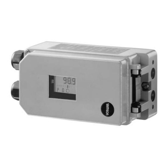
- Page 1 Series 3730 Electropneumatic Positioner Type 3730-1 Fig. 1 · Type 3730-1 Mounting and Operating Instructions EB 8384-1 EN Firmware version 2.0x Edition January 2006...
-
Page 2: Table Of Contents
Contents Contents Page Design and principle of operation ....6 Attachment to the control valve – mounting parts and accessories ..8 Direct attachment . - Page 3 Safety instructions General safety instructions The positioner may only be assembled, started up or operated by trained and experienced personnel familiar with the product. According to these mounting and operating instructions, trained personnel refers to individuals who are able to judge the work they are assigned to and recognize possible dangers due to their specialized training, their knowledge and experience as well as their knowledge of the relevant standards.
- Page 4 Versions Type 3730-1 X 0 0 0 0 0 0 0 0 X 0 0 X 0 0 0 Article code Explosion protection Without II 2 G EEx ia IIC T6 acc. to ATEX Ex ia/Ex n acc. to FM/CSA II 3 G EEx nA/nL II T6 and II 3 D IP 65 T 80 °C acc.
- Page 5 Technical data Positioner Direct attachment to Type 3277: 3.6 to 30 mm Travel, adjustable Attachment acc. to IEC 60534-6: 3.6 to 200 mm or 24° to 100° with rotary actuators Adjustable within the initialized travel/angle of rotation; Travel range travel can be restricted to at the maximum Signal range 4 to 20 mA, split-range 4 to 11.9 mA and 12.1 to 20 mA, Reference variable w...
-
Page 6: Design And Principle Of Operation
Design and principle of operation variable) after it has been converted by the Design principle A/D converter (4). operation In case of a system deviation, the operation of the i/p converter (6) is changed so that The electropneumatic positioner is mounted the actuator (1) is filled or vented via the to pneumatic control valves and is used to downstream air capacity booster (7). - Page 7 Design and principle of operation Air capacity booster Control valve Pressure regulator Travel sensor Flow regulator PD controller 10 Volume restriction A/D converter 11 Limit switches Microcontroller i/p converter 12 Display Fig. 2 · Functional diagram EB 8384-1 EN...
-
Page 8: Attachment To The Control Valve - Mounting Parts And Accessories
– mounting parts and accessories The positioner can be attached either di- rectly to a SAMSON Type 3277 Actuator or according to IEC 60534-6 (NAMUR) to con- trol valves with cast yokes or rod-type yokes as well as to rotary actuators according to VDI/VDE 3845. - Page 9 Max. lever pin position 3277-5 20.0 3277 120/240/350 35.4 Actuators 50.0 Travel table for attachment according to IEC 60534-6 (NAMUR) SAMSON valves Other valves/actuators Required Assigned lever pin position Rated travel mm Min. Travel Max. 60 and 120 with 17.6 Type 3510 Valve 25.0...
- Page 10 Attachment to the control valve – mounting parts and accessories Table 1 Direct attachment to Type 3277-5 Actuator Order no. Mounting parts For actuators with 120 cm effective diaphragm area 1400-7452 Switchover plate (old) for Actuator Type 3277-5xxxxxx.00 (old) 1400-6819 Switchover plate new for Actuator Type 3277-5xxxxxx.01 (new) 1400-6822 Accessories...
- Page 11 Attachment to the control valve – mounting parts and accessories Attachment to NAMUR ribs or control valves with rod-type yokes (rod diameter Ø 35 mm or smaller) Table 3 according to IEC 60534-6, see Fig. 5 Travel in mm Lever For actuators Order no.
-
Page 12: Direct Attachment
Attachment to the control valve – mounting parts and accessories Direct attachment 4. Mount cover plate (10) with narrow side of the cut-out opening (Fig. 3, on the 2.1.1 Type 3277-5 Actuator left) pointing towards the signal pressure connection. Make sure that the bonded gasket (14) points towards the actuator Refer to Table 1 on page 10 for the required yoke. - Page 13 Attachment to the control valve – mounting parts and accessories Lever Symbols Switchover plate (9) Disk spring Actuator stem extends Follower pin Follower clamp Attachment left Attachment right Screw plug Stopper Actuator stem Connecting plate retracts Seal rings Pressure gauge bracket Signal pressure Press.
-
Page 14: Type 3277 Actuator
Attachment to the control valve – mounting parts and accessories 2.1.2 Type 3277 Actuator 5. Place positioner on the cover plate in such a manner that the follower pin (2) rests on the top of the follower clamp Refer to Table 2 on page 10 for the required (3). - Page 15 Attachment to the control valve – mounting parts and accessories Lever 12.1 Screw 1.1 Nut 12.2 Stopper or connection for external piping 1.2 Disk spring Switch plate Follower pin Gasket Follower clamp 10 14 Formed seal 10 Cover plate Gasket 11 Cover 12 Connection block Lever M...
-
Page 16: Attachment According To Iec 60534-6
Attachment to the control valve – mounting parts and accessories Attachment according to 3. Mount connecting plate (6) or pressure gauge bracket (7) with pressure gauges IEC 60534-6 (8) on the positioner, making sure both The positioner is attached to the control seal rings (6.1) are seated properly. - Page 17 Attachment to the control valve – mounting parts and accessories Attachment to rod-type yoke Rods with Ø max. 35 mm Attachment to NAMUR rib Additional bracket for actuators with 2800 cm and travel ≥ 60 mm Lever Lever XL and L 14.1 Disk spring Follower pin...
-
Page 18: Attachment To Type 3510 Micro-Flow Valve
Attachment to the control valve – mounting parts and accessories Attachment to Type 3510 Micro-flow Valve The positioner is attached to the valve yoke using a bracket. Refer to Table 3 on page 11 for the required mounting parts as well as the accessories with their order numbers. - Page 19 Attachment to the control valve – mounting parts and accessories Lever Disk spring Follower pin Clamp Connecting plate Seal rings Pressure gauge bracket Pressure gauge mounting kit Bracket Screw Note! Always use the connecting plate (6) included in the accessories to connect supply and output.
-
Page 20: Attachment To Rotary Actuators
(Ø5) included in the Prior mounting the positioner to the accessories and screw tight into the bore SAMSON Type 3278 Rotary Actuator, you for pin position 90°. have to mount the associated adapter (5) to 7. Place positioner on the top pair of the free end of the rotary actuator shaft. - Page 21 Attachment to the control valve – mounting parts and accessories (7, 8) 10.1 Note! Always use the connecting plate (6) included in the accessories to connect supply and output. Never screw threaded parts Control valve opens counterclockwise directly into the housing. Slot Legends Figs.
-
Page 22: Reversing Amplifier For Double-Acting Actuators
Attachment to the control valve – mounting parts and accessories Reversing amplifier for Note! double-acting actuators The sealing plug (1.5) should not be un- screwed out of the reversing amplifier. For the use with double-acting actuators, the The rubber seal (1.4) is not required and positioner must be fitted with a reversing can be removed when the sealing plug is amplifier. - Page 23 Attachment to the control valve – mounting parts and accessories From the positioner Output 38 Supply 9 Control signals to the actuator Reversing amplifier Connecting plate 1.1 Special screws 6.1 O-rings 1.2 Gasket 6.2 Screws 1.3 Special nuts 1.4 Rubber seal 1.5 Sealing plug 1.6 Filter Fig.
-
Page 24: Connections
Connections Connections 3.1.1 Signal pressure gauges To monitor the supply air (Supply) and sig- Pneumatic connections nal pressure (Output), we recommend that pressure gauges be attached (see accesso- Caution! ries in Tables 1 to 5). The threads in the positioner housing are not designed for direct air connection! 3.1.2 Supply pressure The required supply air pressure depends... - Page 25 Connections d = Seat diameter [cm] Δp = Differential pressure across the valve [bar] A = Actuator diaphragm area [cm = Upper bench range of the actuator [bar] If there are no specifications, calculate as follows: Required supply pressure = Upper bench range value + 1 bar Note! The signal pressure at the output...
-
Page 26: Electrical Connections
Connections Electrical connections Caution! The terminal assignment specified in the cer- For electrical installation, you are re- tificate must be adhered to. Reversing the quired to observe the relevant elec- assignment of the electrical terminals may trotechnical regulations and the acci- cause the explosion protection to become in- dent prevention regulations that ap- effective! - Page 27 Nickel-plated brass Order no. 1890-4875 For operation of the limit switches in Type Adapter M20 x 1.5 to ½ NPT 3730-11/-13/-18 Positioners, switching Aluminum, powder-coated amplifiers which comply with Order no. 0310-2149 EN 60947-5-6 must be connected to termi- nals 41/42 and 51/52 in the output circuit.
-
Page 28: Operation
Operation Operation Note! Parameter codes that have been changed The positioner is mainly operated with the are first saved in the EEPROM (protected rotary pushbutton. against power failure) when the display re- The volume restriction must be set first to turns to the status indication mode. -
Page 29: Start-Up
Actuators with a transit time ≥ 1 s do not require the air flow rate to be restricted (MAX). The position of volume restriction Q also de- pends on how the signal pressure is routed at the actuator in SAMSON actuators: EB 8384-1 EN... -
Page 30: Adapting The Display
Start-up The “SIDE“ position applies for actuators Determining the fail-safe with a loading pressure connection at the position side, e.g. Type 3271-5. The “BACK“ position applies for actua- Set the fail-safe position of the control valve tors with a loading pressure connection over Code P2 to ATO (Air to open) or ATC at the back, e.g. -
Page 31: Initialization
Start-up * The positioner must be re-initialized when the setting is changed [...] Default setting Parameter codes Display with status indication Pressure limit 2.4 bar [OFF] Reading direction End position w < [ON] P2 * Fail-safe position [ATO] / ATC End position w >... -
Page 32: Faults
Start-up Faults Note! The time required for the initialization procedure depends on the actuator transit On the occurrence of a fault, the fault sym- time and can take a few minutes. appears at the bottom of the display. By turning the button past Code P0 or Initialization successfully P16 , the respective error code E0 to E15 to-... -
Page 33: Zero Calibration
Start-up Reset error codes Zero calibration The error codes E0, E1, E8 and E9 can be In case of inconsistencies in the closing posi- reset as follows: tion of the valve, e.g. with soft-sealed plugs, it may necessary to recalibrate zero. Start the zero calibration by activating Code P16 as follows: Turn... -
Page 34: Code List
Code list Code list Code Display, values Description [default setting] Parameter codes * The positioner must be re-initialized when the setting is changed Status indication showing basic information. Canceling the fail-safe position with RST is possible. Reading direction The reading direction of the display is turned by 180°. P2 * Parameter to adapt the positioner to how the control valve functions: ATO/ATC... - Page 35 Code list Direction of action of the reference variable w to the travel/rotational >> /<> [>>] angle x (increasing/increasing or increasing/decreasing). On initializing the positioner, the gain is set to the selected value. P8 * Gain K 30/[50] The signal pressure can take on the same pressure as the supply air Pressure limit ON/[OFF] at the maximum [ OFF ] or, in the case that the maximum actuator...
- Page 36 Code list Error codes Zero error With tight-closing function P10 w < set to ON Zero point incorrect. Error may arise when the mounting posi- tion/linkage of the positioner moves or when the valve seat trim is worn, especially with soft-sealed plugs. Remedy Check valve and mounting of the positioner.
- Page 37 Defective ceramic oscillator, positioner continues to run with an in- E11 Hardware ternal RC oscillator, but it should be replaced as soon as possible. Remedy Return positioner to SAMSON AG for repair. E12 No factory calibration No factory calibration performed, memory defective.
-
Page 38: Maintenance
Maintenance Maintenance Servicing explosion-protected devices The positioner does not require any mainte- nance. If a part of the positioner on which the explo- sion protection is based needs to be serviced, There are filters with a 100 μm mesh size in the positioner must not be put back into op- the pneumatic connections for supply and eration until an expert has inspected the de-... -
Page 39: Dimensions In Mm
Dimensions in mm Dimensions in mm or connecting plate Pressure gauge bracket NAMUR attachment Lever mm S = 17 M = 50 L = 100 XL = 200 Direct attachment M20 x 1.5 Output (38) Supply (9) Attachment to rotary actuators VDI/VDE 3845 for all sizes of fixing level 2 Output A1... -
Page 40: Test Certificates
EB 8384-1 EN... - Page 41 EB 8384-1 EN...
- Page 42 EB 8384-1 EN...
- Page 43 EB 8384-1 EN...
- Page 44 EB 8384-1 EN...
- Page 45 EB 8384-1 EN...
- Page 46 EB 8384-1 EN...
- Page 47 EB 8384-1 EN...
- Page 48 SAMSON AG · MESS- UND REGELTECHNIK Weismüllerstraße 3 · 60314 Frankfurt am Main · Germany Phone: +49 69 4009-0 · Fax: +49 69 4009-1507 EB 8384-1 EN Internet: http://www.samson.de...