Table of Contents
Advertisement
Quick Links
Advertisement
Table of Contents

Related Manuals for TYAN TN70A-B8026


Summary of Contents for TYAN TN70A-B8026
- Page 1 TN70A-B8026 Service Engineer’s Manual http://www.tyan.com...
- Page 2 http://www.tyan.com...
- Page 3 MITAC assumes no liability whatsoever, and ® disclaims any express or implied warranty, relating to sale and/or use of TYAN products including liability or warranties relating to fitness for a particular purpose or merchantability. MITAC retains the right to make changes to produce descriptions and/or specifications at any time, without notice.
-
Page 4: Fcc Declaration
This Class A digital apparatus complies with Canadian ICES-003. Cet appareil numérique de la Classe A est conforme à la norme NMB-003 du Canada. Notice for Europe (CE Mark) ● This product is in conformity with the Council Directive 2014/30/EU. http://www.tyan.com... - Page 5 Replace only with the same or equivalent type recommended by manufacturer. Dispose of used battery according to manufacturer instructions and in accordance with your local regulations. VCCI-A ● この装置は、クラスA情報技術装置です。この装置を家庭環境で使用すると電波妨 害を引き起こすことがあります。この場合には使用者が適切な対策を講ずるよう要 求されることがあります。 Safety: EN/IEC 60950-1 ● This equipment is compliant with CB/LVD of Safety: EN/IEC 60950-1. http://www.tyan.com...
-
Page 6: About This Manual
How this guide is organized This guide contains the following parts: Chapter 1: Overview This chapter provides an introduction to the TYAN TN70A-B8026 barebones and standard parts list, describes the external components, gives an overview of the product from different angles. -
Page 7: Safety And Compliance Information
Safety and Compliance Information Before installing and using TYAN TN70A-B8026, take note of the following precautions: ·Read all instructions carefully. ·Do not place the unit on an unstable surface, cart, or stand. ·Do not block the slots and opening on the unit, which are provided for ventilation. -
Page 8: Safety Information
You must become familiar with the safety information in this guide before you install, operate, or service TYAN products. Symbols on Equipment Caution. This symbol indicates a potential hazard. - Page 9 · Make sure racks are coupled together if it is a multiple-rack installation. · Make sure the rack is level and stable before installing an appliance in the rack. · Make sure the leveling jacks are extended to the floor. http://www.tyan.com...
- Page 10 If you do not ground the Green/Yellow tab, it can cause an electrical shock due to high leakage currents. · Do not place objects on AC power cords or cables. Arrange them so that no http://www.tyan.com...
- Page 11 TYAN, your authorized TYAN partner, or their agents. Equipment Modifications · Do not make mechanical modifications to the system. TYAN is not responsible for the regulatory compliance of TYAN equipment that has been modified.
- Page 12 – Liquid has been spilled on the product or an object has fallen into the product. – The product has been exposed to rain or water. – The product has been dropped or damaged. – The product does not operate normally when you follow the operating instructions. http://www.tyan.com...
-
Page 13: Table Of Contents
Table of Contents Chapter 1: Overview............... 15 About the TYAN TN70A-B8026 ..........15 Product Models ............... 15 Features .................. 16 Standard Parts List ..............23 1.4.1 Box Contents ..............23 1.4.2 Accessories ..............23 ... - Page 14 3.14 Removing the Motherboard ............ 78 Appendix I: Cable Connection Tables .......... 79 Appendix II: Fan and Temp Sensors ..........85 Appendix III: FRU Parts Table ............89 Appendix IV: Technical Support ........... 91 http://www.tyan.com...
-
Page 15: Chapter 1: Overview
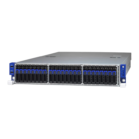
® TYAN also offers the TN70A-B8026 in a version that can support up to twenty-four (24) front hot-swap 2.5” and two (2) internal fixed 2.5” hard drives. The TN70A-B8026 uses TYAN’s latest chassis featuring a robust structure and a solid mechanical enclosure. -
Page 16: Features
Features TYAN TN70A-B8026 (B8026T70AE24HR) Form Factor 2U Rackmount Chassis Model TN70A Dimension (D x W x 27.56" x 17.72" x 3.43" (700 x System 450 x 87mm) Motherboard S8026GM2NRE Gross Weight 30 kg (66 lbs) Net weight 19 kg (42 lbs) - Page 17 (2) PCI-E Gen3 x8 slots ( w/ x0 link or x8 link), (2) PCI-E Gen3 x16 slot ( w/ x16 link or x8 link), PCI-E *Without using OCP 2.0 Mezz card, please contact with Tyan technical support for details. Expansion Slots M7106-L24-3F, M7106-R24-3F, Pre-install TYAN...
- Page 18 FAN PWM Duty Cycle, Console Redirection, ACPI 6.1, SMBIOS 3.1/PnP/Wake on LAN, ACPI sleeping states S5 Please refer to our AVL support Operating System OS supported list lists. FCC (DoC) Class A CE (DoC) Class A Regulation VCCI Class A CB/LVD Class A http://www.tyan.com...
- Page 19 90%, non-condensing at 35° Humidity RoHS RoHS 6/6 Compliant Yes Manual (1) Quick Installation Guide Package Contains Installation CD (1) TYAN Device Driver CD Barebone (1) TN70A-B8026 Barebone TYAN TN70A-B8026 (B8026T70AV16E8HR) Form Factor 2U Rackmount Chassis Model TN70A Dimension (D x W x 27.56"...
- Page 20 PCI-E Gen3 x8 slots ( w/ x0 link or x8 link), (2) PCI-E Gen3 x16 PCI-E slot ( w/ x16 link or x8 link), *Without using OCP 2.0 Mezz card, please contact with Tyan Expansion Slots technical support for details. Pre-install TYAN M7106-L24-3F, M7106-R24-3F Riser Card (1) PCI-E Gen3 x16 OCP 2.0...
- Page 21 System Monitoring Voltage memory, chipset & power supply Over temperature warning indicator, Fan & PSU fail LED indicator Others Watchdog timer support Onboard Chipset Onboard Aspeed AST2500 Server Management AST2500 iKVM IPMI 2.0 compliant baseboard Feature management controller (BMC), http://www.tyan.com...
- Page 22 - 40° C ~ 70° C (-40° F ~ 158° Non-operating Temp. Operating Environment In/Non-operating 90%, non-condensing at 35° Humidity RoHS RoHS 6/6 Compliant Yes Manual (1) Quick Installation Guide Package Contains Installation CD (1) TYAN Device Driver CD Barebone (1) TN70A-B8026 Barebone http://www.tyan.com...
-
Page 23: Standard Parts List
Standard Parts List This section describes TN70A-B8026 package contents and accessories. Open the box carefully and ensure that all components are present and undamaged. The product should arrive packaged as illustrated below. 1.4.1 Box Contents TN70A-B8026 Box Content: 2U barebone, (24) hot swap HDD bays... -
Page 24: About The Product
SATA hard drives (internal fixed) HDD14 HDD1 HDD2 HDD15 HDD3 HDD16 HDD4 HDD17 HDD5 HDD18 HDD6 HDD19 HDD7 HDD20 HDD8 HDD21 HDD9 HDD22 HDD10 HDD23 HDD11 HDD24 HDD12 Front USB Bezel (M1702T70-USB pre-installed) HDD13 Front Panel Bezel (M1701T70-FPB pre-installed) http://www.tyan.com... - Page 25 System is turned on. Power LED Blinking Green System is under S1 or S3 state. Power Off. Fan fail / over temperature / over Orange IPMI/Warning voltage / PSU fail Green No failure Blue System identified ID LED System not identified http://www.tyan.com...
-
Page 26: System Rear View
1.5.2 System Rear View PSU1 PSU0 Dedicated IPMI Port (LAN1) USB3.0 Ports VGA Port Serial Port (COM1) RJ45 LAN Port 2 (LAN2) RJ45 LAN Port 1 (LAN3) ID LED ID LED Button PCIE Slots http://www.tyan.com... - Page 27 Green 10 Mbps Active Blinking Green Link Green Solid Green 100 Mbps Active Blinking Green Solid Green Link Green Solid Yellow 1000 Mbps Active Blinking Green Solid Yellow Link Yellow Solid Yellow 10 Gbps Active Blinking Yellow Solid Yellow http://www.tyan.com...
-
Page 28: System Top View
(2) 2.5” fixed HDDs/SSDs FAN2 Air Duct Riser Card Bracket (M2093 + FAN3 M7106-L24-3F Riser Card pre-installed) Riser Card Bracket (M2093 + FAN4 M7106-R24-3F Riser Card pre-installed) NOTE: Two (2) M2093 riser cards are FAN5 pre-installed in B8026T70AE24HR only. http://www.tyan.com... -
Page 29: Chapter 2: Setting Up
Caution! To avoid damaging the motherboard and associated components, use torque force within the range kgf/cm (4.35 ~ 6.09 lb/in) on each mounting screw for motherboard installation. Do not apply power to the board if it has been damaged. http://www.tyan.com... -
Page 30: Precautions
Working on a system that is connected to a power supply can be extremely dangerous. Follow the guidelines below to avoid damage to TN70A-B8026 or injury to yourself. Ground yourself properly before removing the top cover of the system. -
Page 31: Installing Motherboard Components
CPUs, memory modules, HDD and PCI-E cards. 2.1.1 Removing the Chassis Cover Follow these instructions to remove the TN70A-B8026 chassis cover. Unscrew the rear top cover on the back side. Slide to lift up the rear top cover. Unscrew the front top cover and pull the latches aside simultaneously to slide the front top cover out. - Page 32 Lift up the rear top cover. http://www.tyan.com...
-
Page 33: Removing The Riser Card Brackets
2.1.2 Removing the Riser Card Brackets Follow these instructions to remove the PCI-E Riser Card Brackets. Unscrew to release the PCI-E Riser Card Brackets. Disconnect the Oculink cables. http://www.tyan.com... - Page 34 Lift up the Riser Card Brackets. http://www.tyan.com...
-
Page 35: Removing The Air Duct
2.1.3 Removing the Air Duct Follow these instructions to remove the Air Duct. Refer to Section 2.1.2 Removing the Riser Card Brackets to remove the Riser Card Brackets before you start. Life up the air duct. http://www.tyan.com... -
Page 36: Installing The Cpu And Heatsink
The force frame will automatically eject after the captive screws are being released. By placing your both index fingers on the sides on the metal handle, pull to release the rail frame. Then lift the rail frame to its fully open position. http://www.tyan.com... - Page 37 During installation, observe the followings: a. make sure to push the carrier frame with package towards the end of the rail frame until it clicks into place. b. do not drop the carrier frame or touch the package pad to avoid component damage. http://www.tyan.com...
- Page 38 Carefully close the rail frame with the installed package. Then push both edges of the rail frame firmly until it locks in place. Close the force frame. Then use a T20 Torx screwdriver to tighten the screws to secure the force frame in a sequential order (123). http://www.tyan.com...
-
Page 39: Installing The Memory
Press the memory slot locking levers in the direction of the arrows as shown in the following illustration. Align the memory module with the slot. When inserted properly, the memory slot locking levers lock automatically onto the indentations at the ends of the module. http://www.tyan.com... -
Page 40: Installing Hard Drives
2.1.6 Installing Hard Drives The TN70A-B8026 can support up to twenty-four (24) 2.5” hard drives. Follow these instructions to install a hard drive. Press the locking lever latch to pull the locking lever open. Slide the HDD tray out. Remove the 4 screws. - Page 41 Place a hard drive into the drive tray. Use 4 screws to secure the HDD. Reinsert the HDD tray into the chassis and press the locking lever to secure the tray. http://www.tyan.com...
- Page 42 Installing internal fixed HDD Unscrew to take out the supplementary 2.5” HDD bracket. Insert the blue rubber screws to the HDD bracket. Insert the 2.5” hard drives into the bracket and secure them with eight screws. http://www.tyan.com...
- Page 43 Reinstall the HDD bracket. Screw it firmly to the chassis. Connect the cables. NOTE: After installing or hot-swapping the hard drives, please rescan all hard drives under the Windows OS. http://www.tyan.com...
-
Page 44: Installing The Pci-E Cards
2.1.7 Installing the PCI-E Cards The TN70A-B8026 supports two PCI-E Riser Card Brackets. Follow these instructions to install PCI-E cards. Unscrew to take off the dummy brackets. Insert the PCI-E card (M2093) as shown. Screw the PCI-E card to the Riser Card Bracket. -
Page 45: Rack Mounting
Screw packet in accessory kit 2.2.1 Installing the Server in a Rack NOTE: Before mounting the TYAN TN70A-B8026 in a rack, ensure that all internal components have been installed and that the unit has been fully tested. Screw Kit List Screw... -
Page 46: Installing The Inner Rails To The Chassis
Follow these instructions to install the inner rails to the chassis. Take out the rails and identify the front and rear end of the single rail. Press the locking tab to draw out the inner rail from the rail assembly. http://www.tyan.com... - Page 47 Install the inner rail to the chassis. Push the inner rail forwards to lock the rail in place. Before http://www.tyan.com...
- Page 48 After Repeat the same procedures for the other side. The installation of the inner rail is now complete. http://www.tyan.com...
-
Page 49: Installing The Outer Rails To The Rack
Installing the Outer Rails to the Rack NOTE: Before mounting the TYAN TN70A-B8026 in a rack, ensure that all internal components have been installed and that the unit has been fully tested. However, to make the installation easier, we suggest that you remove all HDD trays before you insert the chassis to the rack. - Page 50 Slide the chassis back into the rack. Screw the chassis to the rack using 2pcs screw B (M5L10). The installation is now complete. http://www.tyan.com...
-
Page 51: Removing The Server From A Rack
2.2.4 Removing the Server from a Rack Follow these instructions to remove the TYAN TN70A-B8026 from an industry standard 19” rack. Unscrew the chassis from the rack. Slide the chassis forwards. Press the locking tab on both sides simultaneously to slide the chassis out from the rack. - Page 52 NOTE http://www.tyan.com...
-
Page 53: Chapter 3: Replacing Pre-Installed Components
Chapter 3: Replacing Pre-Installed Components Introduction This chapter explains how to replace the pre-installed components, including the Motherboard, Front Panel Board, USB Board, PCI-E Riser card, System fan, and Power supply unit, etc. Disassembly Flowchart The following flowchart outlines the disassembly procedure. http://www.tyan.com... -
Page 54: Replacing Motherboard Components
Removing the Cover Before replacing any parts you must remove the chassis cover. Follow Section 2.1.1 Removing the Chassis Cover to remove the cover of the TN70A-B8026. Replacing PCI-E Riser Cards The TN70A-B8026 has two pre-installed PCIE riser cards. -
Page 55: Riser Card Features
PCIe x16 Slot x1 / PCIe x8 Slot x2 (1) S4P Power Connector M7106-R24-3F Riser Card Support (3) PCI-E Gen 3 Slots Specifications PCIe x1 Slot x1 / PCIe x16 Slot x1 / PCIe x8 Slot x2 (1) S4P Power Connector http://www.tyan.com... - Page 56 M2093 PCI-E OcuLink Card M2093 PCI-E OcuLink Card PCI-E x16 Gen3 slot interface Specifications (2) PCI-E x8 OcuLink connector http://www.tyan.com...
-
Page 57: Replacing The Front Panel Board
Replacing the Front Panel Board Follow these instructions to replace the M1701T70-FP Front Panel Board. Unscrew to release the Front Panel Board cover. Remove the Front Panel Board cover. http://www.tyan.com... - Page 58 Unscrew the Front Panel Board. Disconnect the Front Panel Board to replace a new one. Follow the steps described earlier in reverse to reinstall the Front Panel Board. http://www.tyan.com...
-
Page 59: Front Panel Board Features
Power On/Off LED Color: Green (after power on) ID LED Color: Blue LEDs Warning (IPMI) LED Dual Color: Yellow (Warning) / Green (Normal) RESET button Push buttons ID button Power On/Off button with Power On/Off LED http://www.tyan.com... -
Page 60: Fpb Led And Connector Pin Definition
*: For more information on the Chassis Locate LED, please visit our Web site for the latest Pilot II Software Configuration Guide. J1: FPIO connector Definition Definition PW_LED+ +5VSB ID_LED+ PW_LED- ID_LED- HD_LED+ LED_FAULT1- HD_LED- LED_FAULT2- PWR_SW+ LAN_ACT PWR_SW- LAN_LINK# RESET+ SMB_DAT RESET- SMB_CLK ID_SW- Temp_sensor SMB_ALR FPB_HDD_ACTIVITY_G- SMB_CLK FPB_HDD_FAULT_R- SMB_DAT http://www.tyan.com... -
Page 61: Replacing The Usb Board
Replacing the USB Board Follow these instructions to replace the M1702T70-USB USB Board. Unscrew to release the USB front cover. Remove the USB front cover. http://www.tyan.com... - Page 62 Unscrew the USB Board. Disconnect the USB Board to replace a new one. Follow the steps described earlier in reverse to reinstall the USB Board. http://www.tyan.com...
-
Page 63: Usb Board Features
Connector Pin Definition J2: 2x5-pin Connector for FP Connector of Motherboard Definition Description Definition Description VCC_USB USB power VCC_USB USB power USB_P0_N Port1(J1) USB- USB_P1_N Port2(J3) USB- USB_P0_P Port1(J1) USB+ USB_P1_P Port2(J3) USB+ GND1 Ground GND2 Ground No connect http://www.tyan.com... -
Page 64: Replacing The Power Distribution Board
Replacing the Power Distribution Board Follow these instructions to replace the M1601T70-D-PDB-STD power distribution board. Disconnect all cables. Unscrew to replace with a new power distribution board. Follows the procedures described in reverse order to reinstall the power distribution board. http://www.tyan.com... -
Page 65: Power Distribution Board Features
Support (1+1) redundant power supply (1) 2x12 pin SSI Power connector (8) 2x4 pin Power connector Specifications (1) 2x2 pin Power connector (2) B4P Power connector (4) S4P Power connector (1) 1x5 pin IPMI connector http://www.tyan.com... -
Page 66: Replacing The System Fan
Replacing the System Fan Follow these instructions to replace the system fan. Take out the fan module. Loosen the screws on both sides. http://www.tyan.com... - Page 67 Push the latch in the direction as the arrow shown to release the fan from the fan holder. Remove the fan holder to replace with a new fan. Reinstall the fan module into the fan cage. http://www.tyan.com...
-
Page 68: Replacing The Fan Board
Remove all fan modules. c. Unscrew the fan cage and then lift it up. Flip the Fan Cage over to unscrew the Fan Board for replacement. Follow the steps described in reverse order to reinstall the fan cage. http://www.tyan.com... -
Page 69: Fan Board Features
(2) 1x4pin R/A Power Connector (8) 2x2pin Fan Connectors Integrated I/O (1) 2x10pin Barebone Fan Connector (J8) (1) 2x2pin Connector for Mainboard 3.10.2 Fan Board LED Definitions FAN Status Green LED(Right) Red LED(Left) With Fan Without Fan http://www.tyan.com... -
Page 70: Connector Pin Definitions
3.10.3 Connector Pin Definitions Power Connector (PW1/PW2) Definition Definition +12V Barebone Fan Connector (J8) Definition Definition FANIN1 FANIN6 FANIN2 FANIN7 FANIN3 FANIN8 FANIN4 SIO_FANIN1 FANIN5 SIO_ FANIN2 MB_PWM2 MB_PWM1 SIO_ FANIN3 SMBUS_3V3_DATA SIO_ FANIN4 SMBUS_3V3_CLK VDD_3.3_AUX MB_PWM3 http://www.tyan.com... -
Page 71: Replacing The Hdd Backplane Board
3.11 Replacing the HDD Backplane Board Follow these instructions to replace the M1244G70-BP6-8-B8026 M1285T70A-BPE-8 HDD BP Board in your system. Unscrew the HDD cage from the chassis. Slide the HDD cage out of the chassis. http://www.tyan.com... - Page 72 Unscrew the HDD cage to take out the HDD BP Board bracket. Unscrew the HDD BP Board bracket to replace with a new HDD BP Board. Reinstall the HDD BP Board bracket into the chassis following the steps described earlier in reverse order. http://www.tyan.com...
-
Page 73: Hdd Bp Board Features
3.11.1 HDD BP Board Features Front view: Rear view: M1244G70-BP6-8-B8026 HDD Backplane Board Form Factor 8-layer PCB (1) 8-pin Power Connector (PW3) (2) Mini-SAS Connector Integrated I/O (8) HDD Connector, 2.5” SAS/SATA 12Gb/s & hot-swap support http://www.tyan.com... - Page 74 Front view: Rear view: M1285T70A-BPE-8 HDD Backplane Board Form Factor 6-layer PCB, 76.8mm x 134.4mm (8) 2.5” hot-swap NVMe SSDs support (4) OcuLink connector Specifications (1) 2x4 pin power connector (1) SGPIO connector (1) CPLD JTAG connector http://www.tyan.com...
-
Page 75: Connector Pin Definitions
3.11.2 Connector Pin Definitions M1244G70-BP6-8-B8026 HDD Backplane Board PW3: 8-pin Power Connector Definition Definition +12V +12V +12V +12V http://www.tyan.com... -
Page 76: Replacing The Power Supply
Follow these instructions to replace the power supply modules in your system. Press and hold the latch to pull the power supply out. After replacing a new power supply, press and hold the latch to push the power supply back into the chassis. http://www.tyan.com... -
Page 77: Disconnecting All Motherboard Cables
3.13 Disconnecting All Motherboard Cables Follow these instructions to remove all cables. Remove all components installed on the motherboard before you start. Disconnect all cables. http://www.tyan.com... -
Page 78: Removing The Motherboard
3.14 Removing the Motherboard After removing all of the aforementioned cables, follow the instructions below to remove the motherboard from the chassis. Remove the nine screws securing the motherboard to the chassis. Carefully lift the motherboard from the chassis. http://www.tyan.com... -
Page 79: Appendix I: Cable Connection Tables
MB PESLOT2 OCuLink M2093(Card)J1 MB PESLOT2 OCuLink M2093(Card)J2 OCuLink OCUL7 OCuLink OCUL8 B8026T70AV16E8HR SKU OCuLink 8X Backplane (BP) Board to S8026MB HDD BP 1 Cable Connect to S8026MB M1285T70A-BPE-8 OCuLink OCUL3 OCuLink OCUL4 http://www.tyan.com... - Page 80 System FAN Control Cable FAN Board Connect to S8026 MB M1806G70-FB FAN_HD1 Front Panel Control Cable Front Panel Connect to S8026 MB M1701T70-FPB FPIO_2 Front Panel USB Cable Front Panel Connect to S8026 MB M1702T70-USB USB3_FPIO1 http://www.tyan.com...
- Page 81 HDD BP3 PW1 Power Supply Cables M1601T70-D-PDB Connect to internal 2.5" HDD/SSD internal 2.5" HDD/SSD internal 2.5" HDD/SSD SATA HDD Cable S8026 MB Connect to internal 2.5" HDD/SSD SATADOM1 internal 2.5" HDD/SSD SATADOM2 internal 2.5" HDD/SSD http://www.tyan.com...
- Page 82 S8026 MB Connector Location M1285T70A-BPE-8 HDD BP Board Connector Location http://www.tyan.com...
- Page 83 M2093 PCI-E OcuLink Card Connector Location M1244G70-BP6-8-B8026 HDD BP Board Connector Location M1806G70-FB Fan Board Connector Location http://www.tyan.com...
- Page 84 M1702T70-FPB Front Panel Board Connector Location M1702T70-USB Front USB Board Connector Location M1601T70-D-PDB-STD Connector Location http://www.tyan.com...
-
Page 85: Appendix Ii: Fan And Temp Sensors
NOTE: The red dot indicates the sensor. Fan and Temp Sensor Location: Fan Sensor: It is located in the third pin of the fan connector, which detects the fan speed (rpm) Temp Sensor: SYS_Air_Outlet ,and MB_Air_Inlet http://www.tyan.com... - Page 86 BIOS Temp Sensor Name Explanation: http://www.tyan.com...
- Page 87 Fan speed of SYS_FAN_5 SYS_FAN_6 Fan speed of SYS_FAN_6 SYS_FAN_7 Fan speed of SYS_FAN_7 SYS_FAN_8 Fan speed of SYS_FAN_8 SYS_FAN_9 Fan speed of SYS_FAN_9 SYS_FAN_10 Fan speed of SYS_FAN_10 SYS_FAN_11 Fan speed of SYS_FAN_11 SYS_FAN_12 Fan speed of SYS_FAN_12 http://www.tyan.com...
- Page 88 NOTE http://www.tyan.com...
-
Page 89: Appendix Iii: Fru Parts Table
Appendix III: FRU Parts Table TN70A-B8026 FRU Parts Item Model Number Part Number Picture Description TF-POWER SUPPLY;SBU,1600 FRU-PS-0130 471100000193 W,DELTA,DPS-1600EB B,(S0F),1U MODULE,REV.S0F TF-FAN;12V,PFC1212DE-SP0,4800RPM,120X120 FAN Kit CFAN-0410 541379090002 X38,DELTA, 4-pin HF-HEATSINK;SBU,AL/CU,SOLDERLING+PIPE, Heatsink & 3647-2U-NARROW-PASSIVE HEATSINK, FRU-TH-0220 343T56600001 Cooler 1A0-D042800991, 108.0X78.0X64.0MM, SCREW,TN70A-B8026... - Page 90 NOTE http://www.tyan.com...
-
Page 91: Appendix Iv: Technical Support
MITAC serves multiple market segments with the industry’s most competitive services to support them. Please feel free to contact us directly for this service at tech-support@tyan.com Help Resources: 1. See the POST codes section of this manual. - Page 92 (RMA) number. The RMA number should be prominently displayed on the outside of the shipping carton and the package should be mailed prepaid. TYAN will pay to have the board shipped back to you. TYAN® TN70A-B8026 Service Engineer’s Manual V1.0 Document No.: D2400-100 http://www.tyan.com...