ATEN Interface Converter IC-485S User Manual
Rs-232, rs-485 interface converter
Hide thumbs
Also See for Interface Converter IC-485S:
- Manual (20 pages) ,
- User manual (16 pages) ,
- Specifications (6 pages)
Table of Contents
Advertisement
Quick Links
Download this manual
See also:
User Manual
Advertisement
Table of Contents

Related Manuals for ATEN Interface Converter IC-485S


Summary of Contents for ATEN Interface Converter IC-485S
- Page 1 RS-232 - RS-485 INTERFACE CONVERTER IC-485S & IC-485SI User’s Manual @Copyright 1994 ATEN@ International CO., LTD. Manual part NO.PAPE-0075-200 Printed in Taiwan 06/94...
-
Page 2: Package Checklist
PACKAGE CHECKLIST When you purchase this product, it should contain the following elements: IC-485S or IC-485SI Converter Power Adapter (DC9V, 200mA) IC-485S & IC-485SI User’s Manual x 1 Attention: To prevent electric shock caused by lightening, you must provide a ground path by connecting a wire from the Grounding Tab to the earth ground... -
Page 3: Table Of Contents
TABLE OF CONTENTS FUNCTION OVERVIEW ... 1 l-l Introduction ... 1 l-2 Specifications..2 2 INSTALLATION ... 3 2- 1 Installation Procedure..3 2-2 Switch Function Description ... 4 3 OPERATION ... 6 3-l Point-to-Paint/4-Wire Full Duplex ... 8 3-2 Point-to-Paint/2-Wire Half Duplex ... -
Page 4: Installation
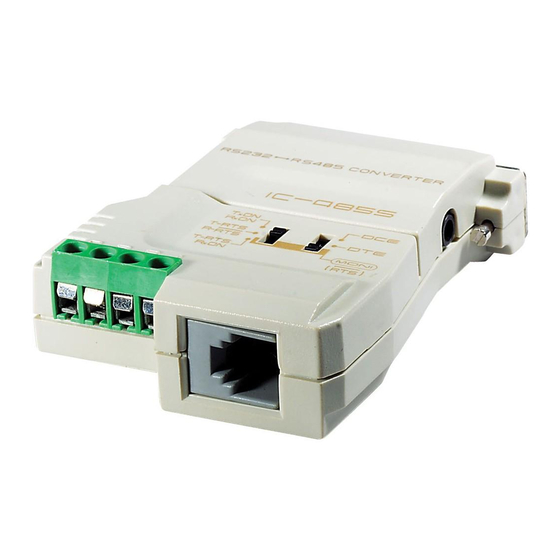
FUNCTION OVERVIEW IC-485S/IC-485SI 1-2 SPECIFICATIONS RS-485/422: A 4 terminal block Connector and RJ-1 l* or GND TAB** SWl:DCE,DTE, MONITOR* selection SW2:TxON. RxON Function Switch SW2:TxRTS, R X X r t SW2:TxRTS. RxON Plastic Enclosure Weight 60 gm 54x74.5x18.5mm Dimensions Figure l-2 IC-485 Specifications Table * RJ-11 Connector &... -
Page 5: Switch Function Description
IC-485S/IC-485SI 2-2 SWITCH FUNCTION DESCRIPTION Refer to the location of the SW1 and SW2, please see Figure 1- 1. IC-485S: IC-485SI: SW 1: Device Mode Selection Position 1: DCE means the IC-485 is set at DCE mode and it must be connected to a DTE device. -
Page 6: Operation
IC-485S/IC-485SI 3 OPERATION The IC-485S & IC-485SI supports 4 kinds of functions in 6 kinds of configurations. They are 1. Point-to-Point Point-to-Point configuration means two devices which locate at two different places can be linked together to communicate through a couple of IC-485 devices. - Page 7 IC-485S/IC-485SI 3-1 POINT-TO-POINT/~-W PLEX Configuration: 1 DCWJITE ) TxON,RxON 1 DCE/DTE ) TxON,RxON Figure 3- 1 POINT-TO-POINT/4-WIRE FULL DUPLEX In above Figure if the PC 1 is a DTE device, then the Device A should set the SW1 to DCE. If the PC1 is a DCE device, then the Device A should set the SW1 to DTE.
-
Page 8: Multidrop/4-Wire Full Duplex
IC-485S/IC-485SI 3-3 MULTIDROP/4-WIRE FULL DUPLEX PC1 => COM1/ COM2 Configuration: DCE/DTE ] TxRTS, RxON Note: Bn means any one of the B 1, Figure 3-3 MULTIDROP/4-WIRE FUL OPERATION ---.- __ =>PC2 COM1/ COM2 =>PC3 COM1/ COM2 =>PC4 COM1/ COM2 Configuration: B2, B3 Note: Bn means any one of the B 1, B2, B3 and so on. -
Page 9: Simplex/Transmit, Receive Only
IC-485S/IC-485SI 3-5 SIMPLEX/ TRANSMIT, RECEIVE ONLY => COM1/ COM2 Configuration: DCE/DTE 1 TxON, RxON DCE/DTE TxON, RxON Note: Bn means any one of the B 1, B2, B3 and so on. Figure 3-5 SIMPLEX/TRANSMIT, REC-EIVE ONLY OPERATION OPERATION 3-6 MONITORING =>PC2 COM1/ COM2... -
Page 10: Others
IC-485S/IC-485SI 4 OTHERS 4-1 TERMINAL BLOCK DEFINITION The four screw terminal block has different defi- nition in different operation modes. In the DCE/DTE mode, the terminal #l (+V) and #2(-V) are configured to transmit data, the transmit- ter; the terminals #3(-V) and #4(+V) are configured to receive data, the receiver. -
Page 11: Appendix Atrouble Shooting
APPENDIX A TROUBLE SHOOTING at the DC 9 V transmission Power Adapter is available. . Check that the IC-485 is plugged securely in PC. . Check that the 4-wire cable is connected properly at If failure of printing is still exists upon aforesaid solutions, please contact your dealer for help. -
Page 12: Preventing Radio & Tv Interference
PREVENTING RADIO & TV INTERFER- ENCE Warning this equipment generates, uses and radi- ates radio frequency energy and if not installed and used in accordance with the instruction manual may cause interference to radio and television reception. It has been tested and found to comply with the limits for a Class A computing device in accordance with the specifications in Subpart J of Part 15 of FCC Rules, which are designed to provide reasonable...