Table of Contents
Advertisement
Quick Links
Download this manual
See also:
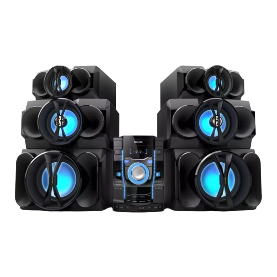
User Manual
Seu Mini Hi-Fi System
TABLE OF CONTENTS
Technical specification ...........................................................1-15
Safety instruction......................................................................2-1
ESD protection......... ................................................................2-2
Set Block diagram ........................................................... .......3-1
Set Wiring diagram ............................................................. ....4-1
Disassembly diagram .......................................................... 5-1-2
Main & Amp board
Layout diagram.................................................................6-4..6-7
Key & Display
Layout diagram.................................................................7-2..7-3
Tuner
Layout diagram........................................................................8-2
Mcu & CD
Layout diagram..................................................................9-3..9-5
Mechanical Exploded view..... .......................................... .....10-1
©
Copyright 2012 Philips Consumer Electronics B.V. Eindhoven, The Netherlands
All rights reserved. No part of this publication may be reproduced, stored in a retrieval system or
transmitted, in any form or by any means, electronic, mechanical, photocopying, or otherwise without
the prior permission of Philips.
215
Published by LX 1
Service Audio
0
Version 1.
Circuit diagram............................................................6-1..6-3
board
Circuit diagram....................................................................7-1
board
Circuit diagram....................................................................8-1
board
Circuit diagram............................................................9-1...9-2
Printed in The Netherlands
Subject to modification
FWM9000/
Page
all
3141 785 37540
Advertisement
Table of Contents

Related Manuals for Philips FWM9000


Summary of Contents for Philips FWM9000
-
Page 1: Table Of Contents
Mechanical Exploded view............10-1 © Copyright 2012 Philips Consumer Electronics B.V. Eindhoven, The Netherlands All rights reserved. No part of this publication may be reproduced, stored in a retrieval system or transmitted, in any form or by any means, electronic, mechanical, photocopying, or otherwise without the prior permission of Philips. -
Page 2: Technical Specification
Display Board Power key Board Usb Board Ac cord Board EQ Board VFD Board Switch power Board Amp Board VERSION VARIATION Type /Versions: FWM9000 x/77 x/78 Service policy Board in used: (LATAM) (BRAZIL) (ARGENTINA) Main BOARD display BOARD amp BOARD... - Page 3 1 - 3 FWM9000 SH 190 content List 1 GENERAL PART 1 - FRONT PANNEL SPECICFICATION 2 GENERAL PART 2 - BACK PANNEL SPECICFICATION 3 GENERAL PART 3 - GENERAL SPECICFICATION 4 GENERAL PART 4 - TECHNICAL SPECICFICATION 5 GENERAL PART 5 - AUDIO SIGNAL SPECICFICATION...
-
Page 4: General Part 1 - Front Pannel Specicfication
Weight ( exclusive packing & batery )26KG Units in Dealercarton Remarks : used into Remark : GENERAL PART 1 - FRONT PANNEL SPECICFICATION Class No Issued Date FWM9000 All Version 12-Feb-09 NAME : SH 190 - 1 CHECK: DATE :... -
Page 5: General Part 2 - Back Pannel Specicfication
Finshing : Chrome Plate s t i & s t i GENERAL PART 1 - BACK PANNEL SPECICFICATION Class No Issued Date FWM9000 All Version NAME : NAME : SH 190 - 2 SH 190 - 2 CHECK: DATE :... -
Page 6: General Part 3 - General Specicfication
Tested according to General Test Instruction refer to PHILIPS standary ( UAN -D1591 ) Measured according to PHILIPS standary ( UAN - L1059 ) unless other wise stated All not mentioned date, please refer to PHILIPS standary ( XUW - 0010 - JUNE 2001 ) Remarks... -
Page 7: General Part 4 - Technical Specicfication
All speaker "L" channel "- "connect to equipment " + "for measurement (because all "L"channel output are reverse ). GENERAL PART 1 - TECHNAICAL SPECICFICATION Class No Issued Date 08-09-2011 FWM9000 All Version NAME : Andy Lai SH 190 - 4 CHECK DATE :... - Page 8 DBB 1 DBB 2 DBB 3 60 Hz(SUB) 1 Hz(SUB) 1khz(host computer) 10K Hz(host computer) GENERAL PART 1 - GENERAL SPECICFICATION Class No Issued Date 08-09-2011 FWM9000 All Version NAME : Andy Lai SH 190 - 5 CHECK DATE :...
-
Page 9: General Part 5 - Audio Signal Specicfication
FREQ Max OFF Max ON 60 Hz 1 kHz 10 kHz GENERAL PART 1 - AUDIO SIGNAL SPECICFICATION ( 2 ) Class No Issued Date 08-09-2011 FWM9000 All Version SH 190 - 6 NAME : Andy Lai CHECK DATE :... - Page 10 No of Timer Settings Nom : 1 sec/day Limit : 2 sec/day Clock Accuracy INDICATORS Remark CLOCK / TIMMER SPECICFICATION Class No Issued Date 08-09-2011 FWM9000 All Version CHECK DATE :...
- Page 11 ( 0 dB, 1 KHz ) >= 45dB > 40HZ-16KHZ(reference 1KHZ) FWM9000 Frequency response @±4 40HZ-100HZ(Reference 63HZ) 200HZ-16KHZ(Reference 1KHZ) USB Measurement at Set Level (*2) Electrical Parameters are to be measured at speaker teminals across 3 ohm load with 500mW output and DSC setting in Jazz Mode...
- Page 12 30db 60db 108 dBu 25db Lim. 40db 65db 116 dBu 45db Nom. FM 108 MHz 30db 60db 108 dBu 25db Lim. Remarks:MAX.Sens -6dB TUNER SPECICFICATION Class No Issued Date 30-Nov-09 FWM9000 All Version SH 190 - 9 CHECK DATE :...
- Page 13 (2) All speaker "L" channel "- "connect to equipment " + "for measurement (because all "L"channel output are reverse ). CD / MP3 SPECICFICATION Class No Issued Date 08-09-2011 FWM9000 All Version NAME : Andy Lai SH 190 -10 CHECK DATE :...
- Page 14 All speaker "R" channel "+ "connect to equipment " + "for measurement. All speaker "L" channel "- "connect to equipment " + "for measurement (because all "L"channel output are reverse ). iPOD SPECICFICATION Class No Issued Date 08-09-2011 FWM9000 All Version CHECK...
- Page 15 23,input leven 1mv rms, FL/FR ch 1KHZ connect main load ±3 10KHZ Remarks : testing with 20 to 20k Hz filter USB SPECICFICATION Class No Issued Date 08-09-2011 FWM9000 All Version NAME : ZC.ZENG SH 190 -9 CHECK DATE :...
- Page 16 1 - 16 VERSION OVERVIEW FWM9000 DEST SURR MAINS SAFETY Wave RANGE GRID AERIAL SOCKET AERIAL SUPPLIED SOC. CORD . SPK. VOLTAGE EN60065 110-127V FM 87.5-108MHz MW 50kHz CLASS II 75 Ohm Coaxial 75 Ohm Pigtail Switched /55 /98 CISPR 13...
- Page 17 2.0 SAFTETY INSTRUCTIONS WAARSCHUWING WARNING Alle IC’s en vele andere halfgeleiders zijn All ICs and many other semi-conductors are gevoelig voor electrostatische ontladingen susceptible to electrostatic discharges (ESD). (ESD). Careless handling during repair can reduce life Onzorgvuldig behandelen tijdens reparatie kan drastically.
-
Page 18: 2.1 Esd Protection
2.1 ESD PROTECTION When the power supply is being turned on, you may not remove this laser cautions label. If it removes, radiation of laser may be received. PREPARATION OF SERVICING Pickup Head consists of a laser diode that is very susceptible to external static electrocity. Although it operates properly after replacement, if it was subject to electrostatic discharge during replacement, its life might be shortened. - Page 19 SAFTY NOTICE SAFTY PRECAUTIONS LEAKAGE CURRENT CHECK Plug the AC line cord directly into a 120V AC outlet (do Measure the AC voltage across the 1500 resistor. not use an isolation transformer for this check). Use an The test must be conducted with the AC switch on and AC voltmeter, having 5000 per volt or more sensitivity.
- Page 20 VFD DRIVER LED DRIVER 3CD LOADER PT6311 BU2090F POWER Board MOTOR DRIVER CD DOOR AM5888S DRIVER IC PICK UP TA7291S FWM998/ FWM9000 8M SERIAL For 1000W FALSH MOTOR CONTROL DATA SST29VF080B CD SERVO BU9543 MLC3895 SWITCH POWER SUPPLY 144pin QFP...
- Page 21 WIRING DIAGRAM...
- Page 22 1)Remove 10 screws A and 8 screws B/C as indicated to loosen the outer plate. 3CD Part Rear Portion Front Portion Bottom Portion...
- Page 23 1)Remove 2 screws A as indicated to loosen the Tuner Board. 2)Remove 2 screws B and 2 screws D as indicated to loosen the Main Board. 3)Remove 3 screws C and 4 screws E as indicated to loosen the Amp Board. 4)Remove 6 screws F as indicated to loosen the AC power Board.
-
Page 24: Circuit Diagram
CIRCUIT DIAGRAM - MAIN BOARD... -
Page 25: Circuit Diagram
CIRCUIT DIAGRAM - AMP BOARD R7162 TO SMPS PB OSC1 R7164 22UF/100V CN701 C760 +40V R732 104P U706 U701 C7227 C743 100P C758 Y702 104P +12V 700KHZ R745 C747 C757 C745 R747 FB1K8 FB1K8 330PF C766 -40V R731 5 6K 680N C744 C756... -
Page 26: Circuit Diagram
CIRCUIT DIAGRAM - AMP BOARD 22UF/100V C7126 SUB-ON/OFF-CTL R782 104P C7231 U703 C7124 104P C7123 C7132 680N C7122 BOOT1 IN1- OUT1 SPK3A L705 VSSA3 OSCREF 15UH TDA895 TH SGND OUT2 8 OHM C7121 BOOT2 15UH 6TS:6TS R768 R775 R777 R779 C7111 IN2- SPK3B... - Page 27 PCB LAYOUT - MAIN BOARD TOP SIDE...
- Page 28 PCB LAYOUT - MAIN BOARD BOTTOM SIDE...
- Page 29 PCB LAYOUT - AMP BOARD TOP SIDE...
- Page 30 PCB LAYOUT - AMP BOARD BOTTOM SIDE...
-
Page 31: Circuit Diagram
CIRCUIT DIAGRAM - DISPLAY BOARD... - Page 32 PCB LAYOUT - DISPLAY/KEY BOARD TOP SIDE...
- Page 33 PCB LAYOUT - DISPLAY/KEY BOARD BOTTOM SIDE...
- Page 34 CIRCUIT DIAGRAM - TUNER BOARD...
- Page 35 PCB LAYOUT - TUNER BOARD...
- Page 36 CIRCUIT DIAGRAM - MCU BOARD...
- Page 37 CIRCUIT DIAGRAM - CD BOARD FWM3000/35000 NC GPIO193 R533 R535 TO CON551 DM+1 3U3/50v C536 DOOR MOTOR CD-R DM-1 CON1 This GND 2PIN/2.5MM/90C must be 100n C532 C520 R536 C533 use AGND 470P C519 100u/16v 470P 1 TRAY POSITION SW SW504 T1 T1 C534...
- Page 38 PCB LAYOUT - MCU BOARD...
- Page 39 PCB LAYOUT - CD BOARD TOP SIDE...
- Page 40 PCB LAYOUT - CD BOARD BOTTOM SIDE...
- Page 41 10-1 10-1 EXPLODED VIEW...