Advertisement
Table of Contents
- 1 Table of Contents
- 2 Safety Instructions and Warnings about Your O.s. Engine
- 3 Operating Temperature
- 4 Notes When Applying an Electric Starter
- 5 Before Starting
- 6 Advice on Selection of Fuel, Glowplug & Propeller
- 7 Start the Engine
- 8 Starting the Engine
- 9 RUNNING-IN (Breaking-In)
- 10 Carburettor
- 11 Care and Maintenance
- 12 Parts List
- 13 View & Parts List
- 14 Parts List
- 15 O.s. Genuine Parts & Accessories
- 16 Three View Drawing
- Download this manual
It is of vital importance, before attempting to operate
your engine, to read the general 'SAFETY
INSTRUCTIONS AND WARNINGS' section on
pages 2-6 of this booklet and to strictly adhere to the
advice contained therein.
Also, please study the entire contents of this
instruction manual, so as to familiarize yourself
with the controls and other features of the engine.
Keep these instructions in a safe place so that you
may readily refer to them whenever necessary.
It is suggested that any instructions supplied with
the aircraft, radio control equipment, etc., are
accessible for checking at the same time.
CONTENTS
ENIGNE CONSTRUCTION,
INTRODUCTION, INSTALLATION
15/25LA CARBURETTOR
AIR-BLEED ADJUSTMENT
TROUBLE SHOOTING WHEN
2-6
THE ENGINE FAILS TO START
7-8
10LA ENGINE EXPLODED VIEW &
9-12
13-15
15LA ENGINE EXPLODED VIEW
& PARTS LIST
16-17
25LA ENGINE EXPLODED VIEW
& PARTS LIST
CARBURETTOR EXPLODED
18-29
29-30
31
1
32-33
34-35
36-37
38-39
40-41
42-44
45-46
47-48
Advertisement
Table of Contents

Related Manuals for O.S. engine MAX-10LA


Summary of Contents for O.S. engine MAX-10LA
-
Page 1: Table Of Contents
It is suggested that any instructions supplied with the aircraft, radio control equipment, etc., are accessible for checking at the same time. CONTENTS SAFETY INSTRUCTIONS AND WARNINGS ABOUT TROUBLE SHOOTING WHEN YOUR O.S. ENGINE THE ENGINE FAILS TO START 32-33 34-35 ENIGNE CONSTRUCTION, CARE AND MAINTENANCE NOTES WHEN APPLYING AN ELECTRIC STARTER 10LA ENGINE EXPLODED VIEW &... -
Page 2: Safety Instructions And Warnings About Your O.s. Engine
As owner, you, alone, are responsible for the safe operation of your engine, so act with discretion and care at all times. If at some future date, your O.S. engine is acquired by another person, we would respectfully request that these instructions are also passed on to its new owner. - Page 3 NOTES This engine was designed for model If you remove the glowplug from the engine aircraft. Do not attempt to use it for any and check its condition by connecting the other purpose. battery leads to it, do not hold the plug with bare fingers.Use an appropriate tool or a Mount the engine in your model securely, folded piece of cloth.
-
Page 4: Operating Temperature
NOTES Adjust the throttle linkage so that the engine For their safety, keep all onlookers stops when the throttle stick and trim lever (especially small children) well back (at on the transmitter are fully retarded. least 20 feet or 6 meters) when preparing Alternatively, the engine may be stopped by your model for flight. -
Page 5: Notes When Applying An Electric Starter
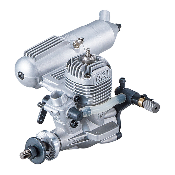
INTRODUCTION Glowplug Cylinder head THE MAX-10LA,15LA,25LA have been developed to meet the requirements of beginners and sport Carburettor Fuel outlet flyers. Of modern design and having a separate needle-valve unit mounted at the rear, where... - Page 6 INSTALLATION It is suggested to use as heavy and rigid as possible engine mounting for highest performance and safe running. Conventional wooden mounting beams should be of rigid hardwood and of at least 12mm or 5/8-in square section. Use at least 3mm steel screws, such as Allen type, with locknuts, for bolting the engine to the bearers..
-
Page 7: Before Starting
INSTALLATION OF SILENCER The angled exhaust of the silencer can be Assembly screw rotated to any desired position in the following Cone baffle manner: Turn to requlred position 1) Loosen the locknut and assembly screw. Exhaust outlet 2) Set the exhaust outlet at the required position by rotating the rear part of the silencer. - Page 8 Fuel Pump O.S. Non-Bubble Weight S To prevent the pickup from adhering to the Alternatively, one of the tank wall under suction and restricting fuel purpose-made manual or Manual Electric flow, slots may be filed I the end of the electric fuel pumps may be used to transfer fuel directly weight.
-
Page 9: Advice On Selection Of Fuel, Glowplug & Propeller
Reminder! ADVICE ON SELECTION OF FUEL, GLOWPLUG & PROPELLER Model engine fuel is poisonous. Do not allow it to Fuel come into contact with the eyes or mouth. Always Use a good quality commercial fuel or one of the blends store it in a clearly marked container and out of shown in the table. -
Page 10: Starting The Engine
STARTING THE ENGINE For accurately centering the starter's rubber drive Be sure to use an electric starter to insert, install an O.S. solid alloy spinner-nut to the start the engine. engine. (Available as an optional extra part). Alternatively, a spinner assembly, enclosing the Never fail to check the tightness of screws propeller boss, may be used, but make sure that it and nuts, especially engine mounting and... - Page 11 Opening and closing of the needle-valve The position where the needle-valve stops is Turn needle-valve clockwise to close (for the fully closed position. It may be convenient leaner mixture). to remember the position of the mark or set- Turn needle-valve counter-clockwise to open screw at this time.
- Page 12 Setting the throttle Hold model securely when starting Assistant should hold the model so that it cannot move forward when the engine starts. Fully closed position Fully opened position Glowplug battery. Place as far to the Set at this Position. rear as possible.
- Page 13 Needle-valve adjustment (1) Engine starts Slowly advance throttle to its fully open If the engine does not start, refer to the position, then gradually close the needle-valve TROUBLE SHOOTING CHART on page 32- until the exhaust sound changes pitch. BEWARE of the rotating propeller.
- Page 14 Needle-valve adjustment (Summary) Practical best (optimum) needle-valve setting Maximum rpm setting("Lean"). 20-30 Clear, high-pitched two-stroke "Rich" needle-valve setting exhaust note when starting the engine. Intermittent, high-pitched two- stroke note superimposed on low "four-stroke" sound. Disconnect battery leads from glowplug at about this point. The engine may stop if the battery leads Exhaust note starts to change.
-
Page 15: Running-In (Breaking-In)
Note: When re-starting the engine on the With the transmitter throttle trim lever fully same day, provided that atmospheric retarded, adjust the throttle servo linkage so that the throttle rotor is fully closed (i.e.engine conditions have not changed significantly, stopped) when the stick is fully retarded. it may be practicable to re-start the engine on its optimum (running) setting. - Page 16 Repeat the procedure while opening and closing the throttle until the best result is obtained.
- Page 17 Cause Corrective action Symptom Factor ..Incorrect heating of Voltage too high or too low. Re-check and readjust referring to "BEFORE Engine fires glowplug. STARTING"..intermittently but Over priming. Continue flipping propeller.
-
Page 18: Care And Maintenance
CARE AND MAINTENANCE Please pay attention to the matters Install an in-line fuel filter between the tank described below to ensure that your engine and carburetor to prevent dirt and dust in the serves you well in regard to performance, tank from entering the carburetor. -
Page 22: Parts List
10H CARBURETOR EXPLODED VIEW & PARTS LIST Description Code No. 21081400 Throttle Lever Assembly 24081300 Throttle Lever Fixing Screw N.+M2.6x6 21081200 Carburetor Rotor 21081100 Carburetor Body 21081300 Throttle Stop Screw 27881120 Carburetor Retaining Screw N.+M3x4 Specifications are subject to alteration for improvement without notice. Type of screw C...Cap Screw M...Oval Fillister-Head Screw F...Flat Head Screw N...Round Head Screw S...Set Screw... -
Page 23: O.s. Genuine Parts & Accessories
20H CARBURETOR EXPLODED VIEW & PARTS LIST Code No. Description 22081408 Throttle Lever Assembly N.+M2.6x7 N.+M3x6 22081313 Throttle Lever Fixing Screw 22381200 Carburetor Rotor 24081600 Air-bleed Screw 22581100 Carburetor Body 22581300 Throttle Stop Screw 22615000 Carburetor Gasket N.+M2.6x15 23081706 Carburetor Retaining Screw N.+M3.5x5 Specifications are subject to alteration for improvement without notice. -
Page 24: Three View Drawing
NON-BUBBLE WEIGHT NON-BUBBLE WEIGHT WITH PLUG GRIP (71531000) (71531010) (71521000) The specifications are subject to alteration for improvement without notice. MAX-10LA THREE VIEW DRAWING SPECIFICATIONS M5x0.8 1.76 cc ( 0.107 cu.in. ) Displacement 13.44mm ( 0.529 in. ) Bore 12.4mm ( 0.488 in. ) Stroke Practical R.P.M. - Page 25 MAX-15LA/25LA THREE VIEW DRAWING 4- 3.3 15LA SPECIFICATIONS 2.49 cc ( 0.1517 cu.in. ) Displacement 15.2mm ( 0.598 in. ) Bore 13.7mm ( 0.539 in. ) Stroke Practical R.P.M. 2,500-18,000 r.p.m. Power output 0.41 ps / 0.42 hp / 17,000 r.p.m. UNF1/4-28 (M5) 138g ( 4.87 oz.