Table of Contents
Advertisement
Quick Links
Be sure to read this manual before servicing. To assure safety from fire, electric shock, injury harmful radiation
and materials, various measures are provided in this Hitachi protable DVD player.
Be sure to read the cautionary items described in the manual to maintain safety before servicing.
1. Do not attempt to modify this product in any way and never perform customized installations without manu-
facturer's approval. Unauthorized modifications will not only void the warranty,but may lead to your being
liable for any resulting property damage or user injury.
2.
Service workshould be performed only after you are thoroughly familiar with all of the following safety che-
cks and servicing guidelines. To do otherwise,increase the risk of potential hazards and injury to the user.
3.
While servicing,use an isolation transformer for protection from A.C. line shock.
*
SAFETY NOTICE....................................................2
*
PRODUCT SPECIFICATIONS.................................3
*
FUNCTIONAL OVERVIEW..................................4-6
*
CONNECTIONS....................................................7-8
*
WIRING DIAGRAM .............................................9
SPECIFICATIONS AND PARTS ARE SUBJECT TO CHANGE FOR IMPROVEMENT
Dec. 2005
Service warning
Contents
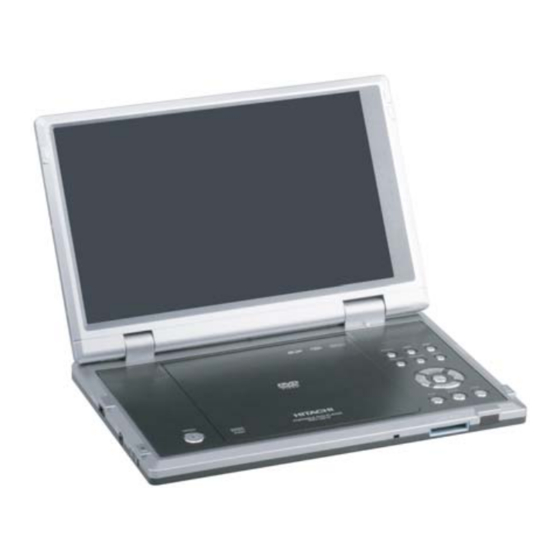
Protable DVD player
Digital Media Systems Group, Hitachi Asia Ltd.
PDV-1021S
Caution
*
PCB WIRING DIAGRAMS.........................................10-12
*
BLOCK DIAGRAM...............................................13
*
SCHEMATIC DIAGRAMS....................................14-17
*
TROUBLESHOOTING........................................18-20
*
REPLACEMENT PART LIST........................................21-36
8
Advertisement
Table of Contents

Related Manuals for Hitachi PDV-1021S


Summary of Contents for Hitachi PDV-1021S
-
Page 1: Table Of Contents
Be sure to read this manual before servicing. To assure safety from fire, electric shock, injury harmful radiation and materials, various measures are provided in this Hitachi protable DVD player. Be sure to read the cautionary items described in the manual to maintain safety before servicing. -
Page 2: Safety Notice
SAFETY NOTICE LASER BEAM CAUTION LABEL When the power supply is being turned on, please don’t remove this laser cautions label. If it removes, radiation of laser may be received. PREPARATION OF SERVICING Pickup Head consists of a laser diode that is very susceptible to external static electrocity. When replacing, please use a conductive mat, soldering iron with ground to protect the laser from damaged by static electricity. -
Page 3: Product Specifications
PRODUCT SPECIFICATIONS Laser Wavelength 650nm Video System PAL/AUTO/NTSC Frequency Response 20Hz ~ 20kHz (+/-1.0dB) Signal/noise Ratio >= 95 dB Audio Distortion + Noise <= -80 dB (1kHz) Channel Separation >= 85 dB Dynamic Range >= 85dB Output Output Level: 2V +/- 10% Audio Output (Analogue Audio) Load Impedance: 10 k ohm Output Level: 0.5Vp-p... -
Page 4: Functional Overview
FUNCTIONAL OVERVIEW Front of Player CARD SLOT Left of Player USB MEMORY Right of Player COMPONENT VIDEO/ PROGRESSIVE SCAN OUT 1. POWER ON/CHG 7. VOLUME Power and charging indicator. Volume control. 8. PHONE 1 & 2 2. CARD SLOT Earphone jacks. Memory card slot. - Page 5 Top of Player 1. LCD SCREEN 8. DIRECTION BUTTONS 2. SPEAKER 9. ENTER 5. PLAY ( 10. MONITOR 3. OPEN ( 11. USB/CARD 4. DISC DOOR 12. MENU 6. PAUSE ( 13. PREV/NEXT ( 7. STOP ( 14. SOURCE...
-
Page 6: Remote Control
TIME SEARCH RETURN CARD/USB 10/0 SETUP MENU MENU ZOOM MUTE REPEAT AUDIO MODE DIGEST HITACHI PDV-RM701 1. SUBTITLE 14. REPEAT A-B 2. OSD (ON-SCREEN DISPLAY) 15. MUTE 3. NUMBER BUTTONS 16. ZOOM 4. SETUP 17. MENU 5. PLAY ( 18. DIRECTION BUTTONS 6. -
Page 7: Connections
CONNECTIONS Before using the player, you may connect the player to a TV and/or an amplifier, a video game console or an optional TV tuner. NOTE: Turn off the power supply to the player and the equipments before making any connection. Connecting to a TV COMPONENT VIDEO/ PROGRESSIVE SCAN OUT... - Page 8 Connecting to a Video Game Console Game Console COMPONENT VIDEO/ PROGRESSIVE SCAN OUT (Yellow) (Yellow) To AV Output (Red) (Red) To AV IN (Black) (White) (White) AV cable (supplied with game console) Female to Female RCA Adaptor (not supplied) NOTE: When you turn on the player, press button repeatedly to select AV IN.
-
Page 9: Wiring Diagram
WIRING DIAGRAM... -
Page 10: Pcb Wiring Diagrams
PCB WIRING DIAGRAMS FUNCTION BUTTON PCB POWER SWITCH PCB HV PCB IF PCB... - Page 11 MAIN PCB (TOP)
- Page 12 MAIN PCB (BOTTOM)
-
Page 13: Block Diagram
BLOCK DIAGRAM... -
Page 14: Schematic Diagrams
SCHEMATIC DIAGRAMS MAIN PCB CIRCUIT DIAGRAM 1... - Page 15 MAIN PCB CIRCUIT DIAGRAM 2...
- Page 16 MAIN PCB CIRCUIT DIAGRAM 3...
-
Page 18: Troubleshooting
TROUBLESHOOTING SYMPTOM: NO POWER, NO GREEN LED start Check if the power cable replace cable/ No defect, return set OK? adapter set to customer AC adapter Check if the replace connector power and play and switch unit button OK? go to other replace MAIN SYMPTOM BOARD... - Page 19 SYMPTOM: THE DVD DRIVE DOES NOT WORK Press the DISC cover switch at the center of the DVD player and turn on the power. Then check whether or not the optical pick- start up lens of the DVD drive lights. CAUTION: Visible laser radiation when open and interlock defeated.
- Page 20 SYMPTOM: NO IMAGE OR SOUND COMES OUT FROM THE EXTERNAL INPUT start Replace the main board or the connector SYMPTOM: THE DVD DRIVE DOES NOT OPERATE WITH BATTERY start Install a good battery does the LED lights up orange while the AC adapter is connected and does the DVD drive operate OK? NOTE: - For this check, use a battery which is not fully...
-
Page 21: Replacement Part List
REPLACEMENT PART LIST The following service parts list are available for purchase. Serviceman may quote the components shown in this page for servicing purposes. PRODUCT SAFETY NOTE : Components marked with a have special characteristics important to safety. The use of a substitute replacement part which does not have the same safety characteristics may create shock, fire or other hazards. -
Page 22: Replacement Part List
YZEA7397 A102VW01 TFT LCD YZES00112B HITACHI 10.2" TRAVEL BAG YZES0535B CAR CIGARETTE ADAPTER YZES0577K ADPV18A AC POWER ADAPTER YZES06159 PDV-RM701 REMOTE YZES14211A PDV-1021S OWNER MANUAL (ENGLISH) YZES14211B PDV-1021S OWNER MANUAL (CHINESE) YZES2839 LGK-G1628-161D YZES30918 DVD1210A SPEAKER CONNECT WIRE YZES3421B 20PINHARNESS(L160) - Page 23 CCT5902-0701C SOCKET YZES00112B HITACHI 10.2" TRAVEL BAG YZES0535B CAR CIGARETTE ADAPTER YZES0577J ADPV18A AC POWER ADAPTER YZES06159 PDV-RM701 REMOTE YZES14211A PDV-1021S OWNER MANUAL (ENGLISH) YZES14211C PDV-1021S OWNER MANUAL (RUSSIA) YZES14211D PDV-1021S OWNER MANUAL (ARABIA) YZES2839 LGK-G1628-161D YZES30918 DVD1210A SPEAKER CONNECT WIRE...
- Page 24 YZEA7397 A102VW01 TFT LCD YZES00112B HITACHI 10.2" TRAVEL BAG YZES0535B CAR CIGARETTE ADAPTER YZES0577K ADPV18A AC POWER ADAPTER YZES06159 PDV-RM701 REMOTE YZES14211A PDV-1021S OWNER MANUAL (ENGLISH) YZES14211D PDV-1021S OWNER MANUAL (ARABIA) YZES2839 LGK-G1628-161D YZES30918 DVD1210A SPEAKER CONNECT WIRE YZES3421B 20PINHARNESS(L160)
- Page 25 The components shown in the remaining pages served as a reference only. It is not meant for ordering of components for servicing purposes. Do not quote any components from these lists. REF No. PART No. PART NAME REF No. PART No. PART NAME DVD1210M-B MAIN PCB ASS’Y YZEP11035 Resistor chip 20K...
- Page 26 The components shown in the remaining pages served as a reference only. It is not meant for ordering of components for servicing purposes. Do not quote any components from these lists. REF No. PART No. PART NAME REF No. PART No. PART NAME YZEA9482 YZEP20022B ECJMFF1A226Z...
- Page 27 The components shown in the remaining pages served as a reference only. It is not meant for ordering of components for servicing purposes. Do not quote any components from these lists. REF No. PART No. PART NAME REF No. PART No. PART NAME R168 YZEP11000 Resistor chip 0...
- Page 28 The components shown in the remaining pages served as a reference only. It is not meant for ordering of components for servicing purposes. Do not quote any components from these lists. REF No. PART No. PART NAME REF No. PART No. PART NAME R556 YZEP11009 Resistor chip 1K...
- Page 29 The components shown in the remaining pages served as a reference only. It is not meant for ordering of components for servicing purposes. Do not quote any components from these lists. REF No. PART No. PART NAME REF No. PART No. PART NAME YZEP20101 ECJ2FF1C106Z C103...
- Page 30 The components shown in the remaining pages served as a reference only. It is not meant for ordering of components for servicing purposes. Do not quote any components from these lists. REF No. PART No. PART NAME REF No. PART No. PART NAME C145 YZEP20015 Capacitor chip 0.1uF...
- Page 31 The components shown in the remaining pages served as a reference only. It is not meant for ordering of components for servicing purposes. Do not quote any components from these lists. REF No. PART No. PART NAME REF No. PART No. PART NAME YZEP20015 Capacitor chip 0.1uF CB89...
- Page 32 The components shown in the remaining pages served as a reference only. It is not meant for ordering of components for servicing purposes. Do not quote any components from these lists. REF No. PART No. PART NAME REF No. PART No. PART NAME YZEP6659 Impedance at 100MHz:600...
- Page 33 The components shown in the remaining pages served as a reference only. It is not meant for ordering of components for servicing purposes. Do not quote any components from these lists. REF No. PART No. PART NAME REF No. PART No. PART NAME VD23 YZEP5766D STZ6.2N...
- Page 34 The components shown in the remaining pages served as a reference only. It is not meant for ordering of components for servicing purposes. Do not quote any components from these lists. REF No. PART No. PART NAME REF No. PART No. PART NAME YZEA9482 YZEP20022B ECJMFF1A226Z...
- Page 35 The components shown in the remaining pages served as a reference only. It is not meant for ordering of components for servicing purposes. Do not quote any components from these lists. REF No. PART No. PART NAME REF No. PART No. PART NAME YZEP11009 Resistor chip 1K YZEP11017 Resistor chip 33K...
- Page 36 The components shown in the remaining pages served as a reference only. It is not meant for ordering of components for servicing purposes. Do not quote any components from these lists. REF No. PART No. PART NAME REF No. PART No. PART NAME TRANSISTOR YZEP31100B Ceramic CAP 10uF/16V...
- Page 37 PDV-1021S SC No. 0018E Copyright Digital Media Systems Group, (2005) All rights reserved...