Table of Contents
Advertisement
Available languages
Available languages
Quick Links
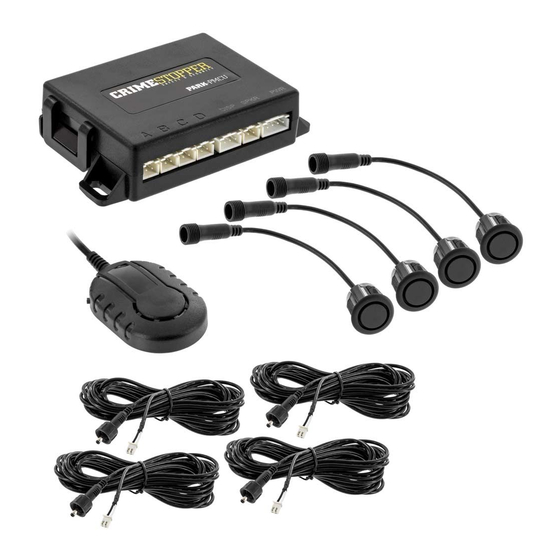
PARK-PMCU
premium parking assist system
CONGRATULATIONS on your choice of a CrimeStopper premium Universal, front or rear mountable parking assist
system. This booklet contains all of the necessary information for connecting and using your parking assist
system. If any questions should arise, contact your installation facility or check out the Knowledge Base at
www.crimestopper.com
Installation manual
1230-62200-01
Advertisement
Table of Contents

Related Manuals for CrimeStopper PARK-PMCU


Summary of Contents for CrimeStopper PARK-PMCU
- Page 1 PARK-PMCU premium parking assist system CONGRATULATIONS on your choice of a CrimeStopper premium Universal, front or rear mountable parking assist system. This booklet contains all of the necessary information for connecting and using your parking assist system. If any questions should arise, contact your installation facility or check out the Knowledge Base at www.crimestopper.com...
-
Page 2: Warranty
WHAT IS COVERED This warranty applies only to CrimeStopper products sold to consumers by authorized CrimeStopper dealers in the United States of America Products purchased by consumers from an Authorized CrimeStopper Dealer in any other country are covered only by that country’s Distributor and not by Rockford Corporation. -
Page 3: Table Of Contents
Introduction The PARK-PMCU is designed as a universal parking assist system. It will work in either the front or back of a vehicle with metal or plastic bumpers and with or without LED displays (displays sold separately). This system was designed to be flexible enough that no matter the vehicle it is being installed into, you will have the correct parts needed. -
Page 4: Wiring
Front Wiring Harness (MAIN CONTROL UNIT) Orange Fuse Ign/Acc + Input Fuse Purple A B C D Reverse + Input Fuse Brown Brake + Input Black Ground - Input Speaker (Audible Alert) Sold Separately NOTE: If only using 2 sensors, connect A &... -
Page 5: Wiring
Rear Wiring Diagram NOTE: IF REVERSE TRIGGER IS NOT TRUE 12V OR IS NOT A CLEAN 12V, CONNECT THE ORANGE WIRE TO IGN/ACC (MAIN CONTROL UNIT) Orange Fuse Fuse Purple A B C D Reverse + Input Fuse Brown Brake + Input Black Ground - Input Speaker... -
Page 6: Specifications
Specifications OPERATING VOLTAGE 12/24V DC OPERATING CURRENT DRAW MAX DRAW @ 12V, LESS THAN 110mA DETECTION RANGE FRONT: 0.3-0.9M/ 1-3FT REAR: 0.3-2.5M/ 1-8.2FT NUMBER OF SENSORS 4 FRONT OR REAR SENSORS PAINTABLE YES, PAINT TRAY INCLUDED AUDIBLE ALERT YES, INCLUDED. ADJUSTABLE VOLUME VISUAL ALERT YES, SOLD SEPERATELY SELF TEST FUNCTION YES INTELLIGENT DETECTION (KNOWS IF... -
Page 7: Key Features
Key Features Key Features: • Dual purpose – This system can be used in the front or rear of a vehicle • 2 sensor options – This system can be installed with either 2 or 4 sensors (using 4 provides a more accurate reading). •... - Page 8 Volume/ Frequency Adjustments FREQUENCY ADJUSTMENT VOLUME ADJUSTMENT The audible alert can be Low Volume changed to make it easier to Medium Volume tell the di erence between the front or rear audible alerts. High Volume Volume Switch High Frequency Low Frequency Frequency Switch...
- Page 9 Front/Rear Selection This system can be installed in the front or rear of a vehicle. - Change the settings from front to rear by moving the indicated jumper plug. JUMPER POSITION “F” - Designates the system is installed into the front of the vehicle. JUMPER POSITION “R”...
- Page 10 Sensor Mounting Height SENSOR INSTALLATION HEIGHT - This will tell the system how high the sensors are from the ground. JUMPER POSITION “54cm-65cm” Select if sensors are mounted 54cm/21.25” – 65cm/25.5” from the ground. JUMPER POSITION “45cm-54cm” Select if sensors are mounted 45cm/17.7” – 54cm/21.25” from the ground.
- Page 11 Activation Time FRONT SYSTEM ACTIVE TIME - When installed in the front of a vehicle the system is activated by pressing the brake. - Once the brake is released the system will remain active either 8 or 20 seconds. Front/ Rear Jumper in FRONT position JUMPER POSTION “1”...
-
Page 12: Settings
Smart Settings SMART SETTINGS - Allows the system to account for a rear mounted spare tire or hitch installed on the vehicle. - Gives you proper warnings without false alarms when backing up. Front/ Rear Jumper in REAR position JUMPER POSITION “1” (DEFAULT) - Normal stopping distance JUMPER POSITION “2”... -
Page 13: Self Test/ Learning Functions
Self Test SELF-TEST This will test all of the connected sensors to make sure that they are working as intended. If there are no issues found during this test, the system will make no alerts If there is a damaged sensor, the system will give and audible alert 3 times. - Page 14 Front Learning Function FRONT INSTALLATIONS: If you have something attached to the front of your vehicle, you will need to “teach” the system to not look at the object mounted in the front. To do this: - Turn the Ignition/Accessory to the ON position - Press and release the brake pedal 10 times in 10 seconds.
- Page 15 Front System Function Pressing the brake pedal will activate the front mounted system.
- Page 16 Rear Learning Function REAR INSTALLATIONS: If you have something attached to the rear of your vehicle, you will need to “teach” the system to not look at the object mounted in the rear. To do this: - Turn the Ignition/Accessory to the ON position - Change the gear selector from “N”...
- Page 17 Rear System Function Placing the vehicle in Reverse will activate the rear mounted system.
- Page 18 Audible Alerts REAR FRONT AUDIBLE ALERT AUDIBLE ALERT Continuous alert Continuous alert Faster multiple Faster multiple repeating alerts repeating alerts Multiple, Multiple, repeating alerts repeating alerts Faster, Single, repeating alert repeating alert Single, repeating alert...
-
Page 19: Sensor Mounting
Sensor Mounting Intructions SENSOR INSTALLATION: • The mounting height of the sensors should be .45m/1.5’ to .6m/2’ . • For optimum performance sensors should be evenly spaced across the front/ rear of the vehicle with as little curve as possible. •... -
Page 20: Sensor Mounting
Sensor Mounting Locations Use tape that will not Use tape that will not damage the vehicles damage the vehicles Mark locations before drilling paint to mark your paint to mark your Mark locations before drilling sensor locations sensor locations Sensor Mounting Height 45cm/17.75”... - Page 21 Sensor Angle CHANGING THE SENSOR HEAD ANGLE TAKE THE SILICONE RING OUT IF ALREADY INSTALLED Make sure that the degree marking is on the top Insert the silicone of the sensor ring into the sensor...
- Page 22 Drilling the Holes Before drilling any holes, be sure that the hole saw is the same size as the sensors you are installing.
- Page 23 Painting Sensors After painting the sensors, let them completely dry The sensors come mounted in a paint tray with the rubber “O” before installing the silicone ring. rings not installed. This will allow for easy color match paint- ing. Once the paint has dried, be sure to install the rubber “O” rings prior to installing the sensors into the vehicle.
- Page 24 Angle Adjustment If there is a gap found between the bumper and the sensor head when using the 10 degree angle head, adjust the angle of the hole as shown below.
-
Page 25: Speaker/ Display Mounting
Mounting the Speaker FRONT MOUNT MOUNTING THE AUDIBLE ALERT Recommended speaker placement REAR MOUNT... - Page 26 Display Placement DISPLAY PLACEMENT (optional) Both the PARK-PLED1 and PARK-PLED2 have multiple mounting options. Within these mounting options you will need to change the way the display reads. Below are the di erent mounting options. E1 – Dash mount E2 – Roof mount, front of vehicle E3 –...
- Page 27 Display Placement Settings Display Placement Settings - Turn the Ignition/Accessory ON and place the gear select in “R” - Press and hold the SET button for 5 seconds until you hear an audible tone. - Press and release the set button again to cycle through the available setting options. - The SET button can be accessed through the small hole in top of the display.
- Page 28 Display Volume Adjustment VOLUME ADJUSTMENT - Turn the Ignition/Accessory ON and place the gear select in “R” - Press and release the SET button to adjust the volume. - The SET button can be accessed through the small hole in top of the display. - The system will automatically save and exit adjustment after 2 seconds of inactivity.
- Page 29 Voice Prompts VOICE PROMPTS/ALERTS The PARK-PLED2 has the option of having voice prompts/alerts. This can be turn ON or OFF using the setting button. - To turn this feature ON or OFF: Default setting is ON - Turn the Ignition/Accessory ON and place the vehicle gear select into “R”. - Press the SET button for 2 seconds.
-
Page 30: Testing
Testing the System - To test the system, use a piece of wood (approx. .3mX1m/ 1’X3.3’). - With the board beyond the furthest trigger point, back up to the board. - The system should trigger once in sensor range. Rear system check Front system check - To test front sensors, repeat the test driving towards the board. -
Page 31: Troubleshooting
B. Do any of the sensors detect the ground? Display alarm sound is too low or too high. A. Press the SET button to adjust the volume to a suitable level Any other questions should be directed to CrimeStopper technical support at 1-800-998-6880. -
Page 32: French
Faisceau de câblage avant Unité de contrôle principale (MAIN CONTROL UNIT) Orange Fusible ALL/ACC+ Entrée Violet Fusible A B C D Déclencheur inverse Fusible Marron Entrée de frein Noir Terre Haut-parleur (Alerte sonore) Vendu séparément NOTE : Si on utilise uniquement 2 détecteurs, connecter A &... - Page 33 Schéma de câblage arrière NOTE : SI LE DÉCLENCHEUR INVERSE N'EST AS UN VRAI 12 V OU N'EST PAS DU 12 V À L'ÉTAT PUR, CONNECTER LE FIL Unité de contrôle principale (MAIN CONTROL UNIT) Orange Fusible ORANGE À L'ALL/ACC Fusible Violet A B C D Déclencheur inverse...
- Page 34 Spécifications TENSION DE FONCTIONNEMENT 12 / 24 V c.c. CONSOMMATION DE COURANT DE FONC- CONSOMMATION MAXI à 12 V, MOINS TIONNEMENT QUE 110 mA PLAGE DE DÉTECTION AVANT 0,3-0,9 M/1-3 pi ARRIÈRE 0,3-2,5 M/ 1-8,2 pi NOMBRE DE DÉTECTEURS AVANT OU ARRIERE DÉTECTEURS À...
- Page 35 Fonctions clés Fonctions clés : • Double usage – Ce système peut être utilisé à l'avant ou à l'arrière d'un véhicule • 2 options de détecteurs – Ce système peut être installé avec soit 2 soit 4 détecteurs (l'utilisation de 4 détecteurs fournit un relevé plus précis). •...
- Page 36 Ajustements de volume/fréquence FREQUENCY ADJUSTMENT VOLUME ADJUSTMENT The audible alert can be Low Volume changed to make it easier to Medium Volume tell the di erence between the front or rear audible alerts. High Volume Volume Switch High Frequency Low Frequency Frequency Switch...
- Page 37 Sélection avant/arrière This system can be installed in the front or rear of a vehicle. - Change the settings from front to rear by moving the indicated jumper plug. JUMPER POSITION “F” - Designates the system is installed into the front of the vehicle. JUMPER POSITION “R”...
- Page 38 Hauteur de montage de détecteurs SENSOR INSTALLATION HEIGHT - This will tell the system how high the sensors are from the ground. JUMPER POSITION “54cm-65cm” Select if sensors are mounted 54cm/21.25” – 65cm/25.5” from the ground. JUMPER POSITION “45cm-54cm” Select if sensors are mounted 45cm/17.7” – 54cm/21.25” from the ground.
- Page 39 Temps d'activation FRONT SYSTEM ACTIVE TIME - When installed in the front of a vehicle the system is activated by pressing the brake. - Once the brake is released the system will remain active either 8 or 20 seconds. Front/ Rear Jumper in FRONT position JUMPER POSTION “1”...
- Page 40 Paramètres intelligents SMART SETTINGS - Allows the system to account for a rear mounted spare tire or hitch installed on the vehicle. - Gives you proper warnings without false alarms when backing up. Front/ Rear Jumper in REAR position JUMPER POSITION “1” (DEFAULT) - Normal stopping distance JUMPER POSITION “2”...
- Page 41 Autotest SELF-TEST This will test all of the connected sensors to make sure that they are working as intended. If there are no issues found during this test, the system will make no alerts If there is a damaged sensor, the system will give and audible alert 3 times.
- Page 42 Fonction d'apprentissage avant INSTALLATIONS AVANT S'il y a quelque chose d'attaché sur l'avant du véhicule, il faudra « apprendre » au système d'ignorer l'objet monté sur l'avant. Pour ce faire : - Mettre le contact/accessoire en position ON (marche). - Appuyer sur et relâcher la pédale de frein à 10 reprises en 10 secondes. - À...
- Page 43 Fonction de système avant Pressing the brake pedal will activate the front mounted system.
- Page 44 Fonction d'apprentissage arrière INSTALLATIONS ARRIÈRE : S'il y a quelque chose d'attaché à l'arrière du véhicule, il faudra « apprendre » au système d'ignorer l'objet monté à l'arrière. Pour ce faire : - Mettre le contact/accessoire en position ON (marche). - Changer le levier de vitesse de « N »...
- Page 45 Fonction du système arrière Placing the vehicle in Reverse will activate the rear mounted system.
- Page 46 Alertes sonores REAR FRONT AUDIBLE ALERT AUDIBLE ALERT Continuous alert Continuous alert Faster multiple Faster multiple repeating alerts repeating alerts Multiple, Multiple, repeating alerts repeating alerts Faster, Single, repeating alert repeating alert Single, repeating alert...
- Page 47 Instructions de montage de détecteurs INSTALLATION DES DÉTECTEURS • La hauteur de montage des détecteurs doit être de 0,45 m/1,5’ à 0,60 m/2’ . • Pour une performance optimale, les détecteurs doivent être uniformément espacés sur l'avant et l'arrière du véhicule avec le moins de courbe possible. •...
- Page 48 Emplacements de montage des détecteurs Use tape that will not Use tape that will not damage the vehicles damage the vehicles Mark locations before drilling paint to mark your paint to mark your Mark locations before drilling sensor locations sensor locations Sensor Mounting Height...
- Page 49 Angle de détecteur CHANGING THE SENSOR HEAD ANGLE TAKE THE SILICONE RING OUT IF ALREADY INSTALLED Make sure that the degree marking is on the top Insert the silicone of the sensor ring into the sensor...
- Page 50 Perçage des trous Before drilling any holes, be sure that the hole saw is the same size as the sensors you are installing.
- Page 51 Peinture des détecteurs After painting the sensors, Les détecteurs sont livrés montés dans un bac à peinture let them completely dry avec les joints toriques en caoutchouc non installés. Ce qui before installing the silicone ring. permettra de peindre en assortissant facilement les couleurs. Une fois la peinture sèche, veiller à...
- Page 52 Ajustement de l'angle If there is a gap found between the bumper and the sensor head when using the 10 degree angle head, adjust the angle of the hole as shown below.
- Page 53 Montage du haut-parleur FRONT MOUNT MOUNTING THE AUDIBLE ALERT Recommended speaker placement REAR MOUNT...
- Page 54 Emplacement d'affichage DISPLAY PLACEMENT (optional) Both the PARK-PLED1 and PARK-PLED2 have multiple mounting options. Within these mounting options you will need to change the way the display reads. Below are the di erent mounting options. E1 – Dash mount E2 – Roof mount, front of vehicle E3 –...
- Page 55 Paramètres d'emplacement d'affichage Display Placement Settings - Turn the Ignition/Accessory ON and place the gear select in “R” - Press and hold the SET button for 5 seconds until you hear an audible tone. - Press and release the set button again to cycle through the available setting options. - The SET button can be accessed through the small hole in top of the display.
- Page 56 Ajustement du volume d'affichage VOLUME ADJUSTMENT - Turn the Ignition/Accessory ON and place the gear select in “R” - Press and release the SET button to adjust the volume. - The SET button can be accessed through the small hole in top of the display. - The system will automatically save and exit adjustment after 2 seconds of inactivity.
- Page 57 Invites vocales VOICE PROMPTS/ALERTS The PARK-PLED2 has the option of having voice prompts/alerts. This can be turn ON or OFF using the setting button. - To turn this feature ON or OFF: Default setting is ON - Turn the Ignition/Accessory ON and place the vehicle gear select into “R”. - Press the SET button for 2 seconds.
- Page 58 Test du système - To test the system, use a piece of wood (approx. .3mX1m/ 1’X3.3’). - With the board beyond the furthest trigger point, back up to the board. - The system should trigger once in sensor range. Rear system check Front system check - To test front sensors, repeat the test driving towards the board.
- Page 59 B. L'un des détecteurs détecte-il la terre ? Le son d'alarme d'affichage est trop bas ou trop haut. A. Appuyer sur le bouton SET pour ajuster le volume à un niveau convenable Toute autre question doit être adressée au support technique CrimeStopper en composant le 1-800- 998-6880.
- Page 60 Arnés de cableado delantero (Unidad de control principal) Naranja Fusible IGN/ACC+ Entrada Fusible Púrpura A B C D Disparo invertido Fusible Marrón Entrada del freno Negro Tierra Altavoz (Alerta sonora) Vendido por separado NOTA: Si solamente está usando 2 sensores, conecte A y D o B y C solamente...
- Page 61 Diagrama de cableado trasero NOTA: SI EL DISPARO DE RE- VERSA NO ES DE 12V VERDA- DEROS, O 12V SIN ALTIBAJOS, CONECTE EL CABLE NARANJA A IGN/ACC (Unidad de control principal) Naranja Fusible Fusible Púrpura A B C D Disparo invertido Fusible Marrón Entrada del freno...
- Page 62 Especificaciones VOLTAJE DE FUNCIONAMIENTO 12/24V CC CONSUMO DE CORRIENTE EN CONSUMO MÁXIMO A 12V, MENOS FUNCIONAMIENTO DE 110mA ALCANCE DE DETECCIÓN DELANTERA: 0.3-0.9 M / 1-3 PIES TRASERA: 0.3-2.5 M / 1-8.2 PIES CANTIDAD DE SENSORES 4 DELANTEROS O TRASEROS SE PUEDEN PINTAR LOS SENSORES SI, SE INCLUYE UNA BANDEJA DE PINTURA ALERTA SONORA SI, INCLUIDA VOLUMEN AJUSTABLE...
-
Page 63: Spanish
Características claves Características claves: • Propósito doble – Se puede usar este sistema en la parte delantera o trasera de un vehículo • 2 opciones de sensor – Se puede instalar este sistema con 2 o 4 sensores (usar 4 proporciona una lectura más exacta). - Page 64 Ajustes del Volumen/ Frecuencia FREQUENCY ADJUSTMENT VOLUME ADJUSTMENT The audible alert can be Low Volume changed to make it easier to Medium Volume tell the di erence between the front or rear audible alerts. High Volume Volume Switch High Frequency Low Frequency Frequency Switch...
- Page 65 Selección Delantera/Trasera This system can be installed in the front or rear of a vehicle. - Change the settings from front to rear by moving the indicated jumper plug. JUMPER POSITION “F” - Designates the system is installed into the front of the vehicle. JUMPER POSITION “R”...
- Page 66 Altura de montaje del sensor SENSOR INSTALLATION HEIGHT - This will tell the system how high the sensors are from the ground. JUMPER POSITION “54cm-65cm” Select if sensors are mounted 54cm/21.25” – 65cm/25.5” from the ground. JUMPER POSITION “45cm-54cm” Select if sensors are mounted 45cm/17.7” – 54cm/21.25” from the ground.
- Page 67 Tiempo de activación FRONT SYSTEM ACTIVE TIME - When installed in the front of a vehicle the system is activated by pressing the brake. - Once the brake is released the system will remain active either 8 or 20 seconds. Front/ Rear Jumper in FRONT position JUMPER POSTION “1”...
- Page 68 Ajustes inteligentes SMART SETTINGS - Allows the system to account for a rear mounted spare tire or hitch installed on the vehicle. - Gives you proper warnings without false alarms when backing up. Front/ Rear Jumper in REAR position JUMPER POSITION “1” (DEFAULT) - Normal stopping distance JUMPER POSITION “2”...
- Page 69 Autocomprobación SELF-TEST This will test all of the connected sensors to make sure that they are working as intended. If there are no issues found during this test, the system will make no alerts If there is a damaged sensor, the system will give and audible alert 3 times.
- Page 70 Función de aprendizaje delantero INSTALACIONES DELANTERAS Si tiene algo conectado a la parte delantera de su vehículo, deberá "enseñar" al sistema que no mire a ese objeto montado en la parte delantera. Para hacerlo: - Coloque el encendido/accesorio en la posición de activado "ON”. - Presione y suelte el pedal de freno 10 veces en 10 segundos.
- Page 71 Función del sistema delantero Pressing the brake pedal will activate the front mounted system.
- Page 72 Función de aprendizaje delantero INSTALACIONES EN LA PARTE TRASERA Si tiene algo conectado a la parte trasera de su vehículo, deberá "enseñar" al sistema que no mire a ese objeto montado en la parte trasera. Para hacerlo: - Coloque el encendido/accesorio en la posición de encendido "ON”. - Cambie el cambio de marcha desde “N”...
- Page 73 Función del sistema trasero Placing the vehicle in Reverse will activate the rear mounted system.
- Page 74 Alertas sonoras REAR FRONT AUDIBLE ALERT AUDIBLE ALERT Continuous alert Continuous alert Faster multiple Faster multiple repeating alerts repeating alerts Multiple, Multiple, repeating alerts repeating alerts Faster, Single, repeating alert repeating alert Single, repeating alert...
- Page 75 Instrucciones de montaje para el sensor INSTALACIÓN DEL SENSOR • La altura de montaje de los sensores debe ser de 0.45 m / 1.5 pies hasta 0.6 m / 2 pies. • Para un desempeño óptimo, los sensores deben estar espaciados uniformemente a través de la parte trasera del vehículo con la menor curvatura posible.
- Page 76 Ubicaciones para el montaje de sensores Use tape that will not Use tape that will not damage the vehicles damage the vehicles Mark locations before drilling paint to mark your paint to mark your Mark locations before drilling sensor locations sensor locations Sensor Mounting...
- Page 77 Angulo del sensor CHANGING THE SENSOR HEAD ANGLE TAKE THE SILICONE RING OUT IF ALREADY INSTALLED Make sure that the degree marking is on the top Insert the silicone of the sensor ring into the sensor...
- Page 78 Perforación de los agujeros Before drilling any holes, be sure that the hole saw is the same size as the sensors you are installing.
- Page 79 Pintura de los sensores Los sensores vienen montados en una bandeja de pintura con After painting the sensors, let them completely dry las juntas tóricas ("O" rings) de caucho no instaladas. Esto before installing the silicone ring. permitirá pintar para tener una fácil combinación de colores. Una vez que la pintura se haya secado, asegúrese de instalar las juntas tóricas de caucho ("O"...
- Page 80 Ajustes del ángulo If there is a gap found between the bumper and the sensor head when using the 10 degree angle head, adjust the angle of the hole as shown below.
- Page 81 Montaje del altavoz FRONT MOUNT MOUNTING THE AUDIBLE ALERT Recommended speaker placement REAR MOUNT...
- Page 82 Ubicación de la pantalla DISPLAY PLACEMENT (optional) Both the PARK-PLED1 and PARK-PLED2 have multiple mounting options. Within these mounting options you will need to change the way the display reads. Below are the di erent mounting options. E1 – Dash mount E2 –...
- Page 83 Ajustes de la ubicación de la pantalla Display Placement Settings - Turn the Ignition/Accessory ON and place the gear select in “R” - Press and hold the SET button for 5 seconds until you hear an audible tone. - Press and release the set button again to cycle through the available setting options. - The SET button can be accessed through the small hole in top of the display.
- Page 84 Ajuste del volumen de la pantalla VOLUME ADJUSTMENT - Turn the Ignition/Accessory ON and place the gear select in “R” - Press and release the SET button to adjust the volume. - The SET button can be accessed through the small hole in top of the display. - The system will automatically save and exit adjustment after 2 seconds of inactivity.
- Page 85 Instrucciones de voz VOICE PROMPTS/ALERTS The PARK-PLED2 has the option of having voice prompts/alerts. This can be turn ON or OFF using the setting button. - To turn this feature ON or OFF: Default setting is ON - Turn the Ignition/Accessory ON and place the vehicle gear select into “R”. - Press the SET button for 2 seconds.
- Page 86 Prueba del sistema - To test the system, use a piece of wood (approx. .3mX1m/ 1’X3.3’). - With the board beyond the furthest trigger point, back up to the board. - The system should trigger once in sensor range. Rear system check Front system check - To test front sensors, repeat the test driving towards the board.
- Page 87 B. ¿Alguno de los sensores detecta el suelo? El sonido de la alarma de la pantalla es demasiado alto o bajo. A. Presione el botón SET para ajustar el volumen a un nivel adecuado Se debe dirigir cualquier otra pregunta al apoyo técnico de CrimeStopper al 1-800-998-6880.