Honeywell Lyric User Reference Manual
Hide thumbs
Also See for Lyric:
- Programming manual (48 pages) ,
- User quick manual (32 pages) ,
- Quick user manual (17 pages)

Related Manuals for Honeywell Lyric


Summary of Contents for Honeywell Lyric
- Page 1 User Reference Guide R ef: LC P5 0 0 - L / L CP 5 00- L C 800-18078 11/15 Rev. F...
- Page 2 Your Honeywell security system is designed for use with devices manufactured or approved by Honeywell for use with your security system. Your Honeywell security system is not designed for use with any device that may be attached to your security system's control or other communicating bus if Honeywell has not approved such device for use with your security system.
-
Page 3: Table Of Contents
TABLE OF CONTENTS OVERVIEW ......................................5 About This Guide ..................................5 Basic Functions ................................... 6 About the Control Panel ................................7 Home Button Status Indications ............................7 The Tools Menu ................................... 8 SECURITY ......................................11 Security Features ..................................11 False Alarm Prevention ................................12 Arming the System ................................... - Page 4 Date / Time ....................................49 Events ......................................50 Keypad ......................................50 TESTING YOUR SYSTEM ................................51 Testing Sensors (Walk Test) ..............................51 Testing Communications ............................... 52 Reboot ......................................52 MAINTENANCE ..................................... 53 Care and Cleaning ..................................53 Battery Replacement ................................53 Communication Module Replacement ..........................
-
Page 5: Overview
(CO) warnings. Lyric monitors sensors and system status to initiate alarms and generate alerts. The system can also send alarm and status messages to a central monitoring station via the cellular phone network or the Internet. -
Page 6: Basic Functions
Lyric™ confirms it has heard a trigger phrase. Confirmation is optional. Three phrases are available and can be changed later. Speak command phrase Lyric executes the operation associated with the command, confirms operation. Five voice commands can be associated with Smart Scenes. -
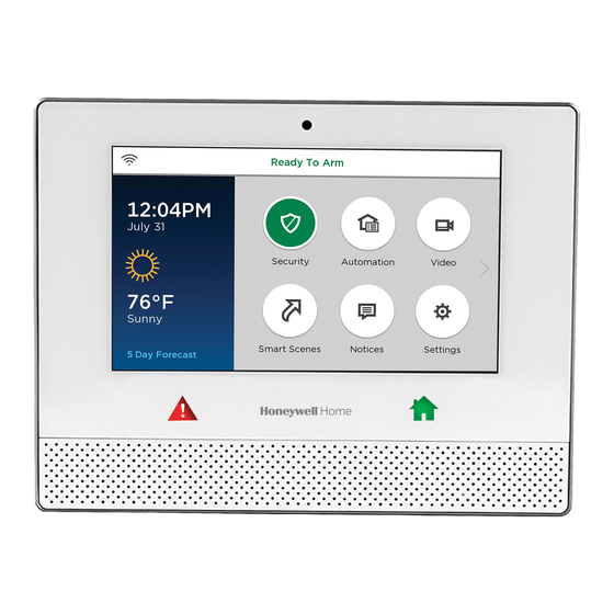
Page 7: About The Control Panel
About the Control Panel Built-in camera Wi-Fi status Status Touch screen Panic Home USB port (underside The display may vary with your connected devices and services. • Security system status appears at the top of the screen. • Wi-Fi® status appears at top left. •... -
Page 8: The Tools Menu
The Tools Menu Home > Security > Tools This menu offers access to most of Lyric’s important settings and maintenance functions. NOTE: The Master User code is required to access Tools. Features available from this screen include: Master User can add/remove other users and control users’... - Page 9 Notices Home > Notices The Notices icon alerts you to new information from your security company. Press for more information. Messages Home > Security > Message Audio messages for all users can be recorded on the Controller. NOTE Audio Messages on the Controller are deleted when the system’s firmware is updated.
-
Page 11: Security
LEAVE IMMEDIATELY and CONTACT THE POLICE from a safe location. Security Features NOTES • For Lyric™ to report alarms over the internet, your Wi-Fi® network MUST have power at all times. • You must arm your security system in order for it to sound alarms. -
Page 12: False Alarm Prevention
Many false alarms are caused by minor problems, such as a door left ajar when exiting the home. Lyric™ includes several features to help prevent false alarms. Note that some are optional or must be programmed by the installer. Disabling these features may increase security, but might also increase the chance of false alarms. -
Page 13: Arming The System
Arming the System The Home button beneath the screen lights green when the system is ready to be armed. If the button is blinking green, the system is not ready to arm. Before arming your system, all protected doors, windows, and other protection zones should be closed or bypassed (see Bypassing Protection Zones). - Page 14 Arm Away Security > Arm Away By default, this mode’s exit delay countdown is accompanied by a beeping sound. Enter a user code or press Quick Arm. (If desired, click Silent Exit first.) 2. The system beeps twice and announces “Armed Away; exit now”. The exit delay countdown begins.
-
Page 15: Disarming The System
Arm Night Security > Arm Stay The Arm Night feature must be enabled by your security professional. Select Arm Stay to display the keypad. 2. Select Arm Night and then enter a user code. 3. The system beeps and announces “Armed Night Stay; exit now”. The exit delay countdown begins. -
Page 16: Entry And Exit Delays
Bypassing Protection Zones (continued) 5. Arm the system as usual. Press Clear Bypass to un-bypass any previously bypassed zones. Any zones with faults must be addressed before arming the system. Entry and Exit Delays NOTE: Entry and exit delay times are programmed by your installer. There is room to jot them down in Your System Information, near the end of this guide. -
Page 17: Panic Alarms
Panic Alarms Available Panic modes may vary, depending on the options programmed by your installer. IMPORTANT Please note the difference between the Panic button below the touchscreen and the different Panic icons on the touchscreen. Activating a Panic Alarm Press and hold the button on the Controller until Panic icons appear on the screen. -
Page 18: Chimes/Voice Annunciations
Audio Alarm Verification features. Lyric™ can give audible notifications when a protected zone opens while the system is disarmed. With Chimes enabled three beeps (or a selectable tone) sound at the Controller when a protected zone is opened. If programmed, a voice announcement also sounds. -
Page 19: Audio Alarm Verification (Two-Way Voice)
• Audio Alarm Verification modes are controlled by the central station. Built-In Camera Lyric’s built-in camera takes a snapshot of the person at the Controller when the system is manually disarmed. Snapshots can be viewed via your Total Connect® account. -
Page 21: Automation: An Introduction
Voice Command You can control a variety of Lyric functions by speaking to the Lyric Controller in plain language. Voice control requires that Smart Scenes be set up and linked to specific spoken phrases. See the Voice Command section for more. -
Page 23: Automation: Smart Scenes
Automation: Smart Scenes Home > Smart Scenes IMPORTANT When the Controller is connected to Honeywell Total Connect™ (or other compatible remote services), Smart Scenes can be created and modified ONLY via remote services. Smart Scenes can be created, deleted or edited ONLY by the Master User. See... -
Page 24: Creating A Smart Scene
Creating a Smart Scene These instructions apply to the creation and operation of Smart Scenes from the Lyric™ Controller’s screen. As above, if your system is connected to Total Connect® remote services, you can create Smart Scenes only through Total Connect. Working with Smart Scenes from Total Anytime Connect differs slightly. - Page 25 7. Select Scheduled. a. Select the type of user who can run the Smart Scene. b. Select Scheduled to display clock and calendar settings. c. Set a time when the Smart Scene will start. Be sure to specify AM or PM. You can select Sunrise or Sunset instead of setting a time on the clock.
- Page 26 b. Restore Zone Type starts the Smart Scene when any zone with the selected Zone Type returns to its normal state (such as a door closing). The options are the same as Event Zone Type options. NOTE: Event Zone Type and Restore Zone Type are separate settings. For example, a given Smart Scene can be triggered by a Fire Alarm (Fire No Verification as the Event Zone Type) OR by an open door closing (Entry/Exit as the Restore Zone Type).
-
Page 27: Hold/Run/Show
10. Press Save. 11. Press to return to the Smart Scenes menu. Hold/Run/Show These controls allow you to pause, preview/execute and review Smart Scenes from the Lyric™ Controller. NOTE Even if you use Total Connect® and can only create and edit Smart Scenes via Total Connect, you CAN use the Hold, Run and Show functions from the Controller. -
Page 29: Automation: Voice Command
• The Controller is designed to hear commands spoken in a normal voice from about 10 feet away. Background noise may affect Lyric’s ability to recognize commands. You may need to speak louder or move closer when there is a lot of background noise. -
Page 30: Voice Command Assignment
2. Lyric™ confirms “Hello; please say your command” (if trigger feedback is enabled) and awaits a command phrase. 3. Speak a command phrase. If Trigger Feedback is enabled, Lyric confirms that it is processing the command. 4. Lyric runs the assigned Smart Scene or opens the Video function. -
Page 31: Counter (Sensitivity Settings)
Resets the Count and Last 10 Accuracy values for all trigger and command phrases. Adjusting Sensitivity If users need to repeat commands or speak abnormally loudly, Lyric’s responsiveness can be improved by changing the Accuracy value. On the list shown above, select the desired phrase. -
Page 33: Automation: Z-Wave Devices
Z-Wave controller. The Z-Wave network supports multiple controllers, allowing Z- Wave remote controls to be used throughout the home. NOTE: In some cases, a Z-Wave device might not report its status to the Lyric Controller when an action is initiated at the device itself. This varies with the manufacturer. -
Page 34: Operating Z-Wave Devices Manually
Operating Z-Wave Devices Manually On the Z-Wave® Device Management menu, select one of the device categories. 2. Select the device you wish to operate. Controls appear. 3. Lighting controls might offer an On/Off button or a slide control for dimmers. 4. -
Page 35: Deleting Z-Wave Devices (Exclude)
Install and test thermostats before Including them in your system. Refer to the device’s instructions for more information about installation. Notes on Thermostats for more information about using thermostats with Lyric™. Deleting Z-Wave Devices (Exclude) To delete (Exclude) a Z-Wave® device: On the Z-Wave Device Management menu, press the arrow. -
Page 36: Failed Devices (Failed Nodes)
View Enrolled Controllers Press to display controller information: Primary or Secondary, Z-Wave Library Rev., Home ID, device type, device ID, node number, manufacturer, Secured or Non-Secured. Reset Controller Press to delete all Z-Wave® nodes in the Controller, and reset the Controller’s Home ID. When prompted, press Yes to confirm. -
Page 37: Garage Doors
Consult your security professional for more information. The Lyric™ Controller can remotely operate and monitor as many as four garage doors. The system can be armed when the garage door is opened. After it is closed, the zone will be monitored without providing burglary protection. -
Page 38: Important Notes About Z-Wave Devices
Z-Wave® enabled devices should never be used to supply power to, or control the On/Off status of medical and/or life support equipment. • Some Z-Wave devices may not communicate low-battery notifications to the Lyric™ Controller. Please pay attention to low battery indications on individual devices and replace batteries when the notifications appear. -
Page 39: Notes On Thermostats
Honeywell is not responsible for property damages due to improper setting of thermostat modes. • If Lyric™ is linked with Total Connect®, 7-day schedules saved in Total Connect will not affect thermostat operation. • In each thermostat used (as many as 6), both of the thermostat’s Zones must be programmed. -
Page 40: Z-Wave Compatibility
Valve EXISTING NETWORK NOTE: Z-Wave products from other manufacturers can be included (added) into the Lyric™ network. Z-Wave devices that are always powered can serve as repeaters regardless of manufacturer. USE OF THESE PRODUCTS IN COMBINATION WITH NON-HONEYWELL PRODUCTS IN A WIRELESS MESH... -
Page 41: Video
Some cameras offer additional options such as pan/tilt and built-in lighting. Adding a Camera • Make sure that the camera is on the same Wi-Fi network as the Lyric system. • Install the camera according to its instructions. With the camera installed: View or list cameras as above. -
Page 42: Video Recovery
Home > Security > Tools > Wi-Fi Config If video from remote cameras is lost or becomes distorted, the system can attempt to reset video streaming. By default, Lyric™ automatically begins to recover video about 60 seconds after Wi-Fi® communication has been restored. -
Page 43: Users And Security Codes
Users and Security Codes Home > Security > Tools > Users Lyric™ uses 4-digit codes to restrict certain functions to selected users. A special 4-digit code can be set to trigger the system’s Duress function. User codes can be used interchangeably when performing system functions (a system armed with one user's code can be disarmed by another user's code), with the exception of the Guest Code described below. -
Page 44: Adding Users And Assigning Codes
Deleting a User The Master user can delete secondary users from the system. Select one of the listed users. 2. At the bottom of the screen, press Delete. Lyric requests confirmation. 3. Press Yes. -
Page 45: User Settings
User Settings User Name Newly-created users are given a default name. To customize a user’s name: Press Name at upper left on the display. A keyboard appears. 2. Press Clear to delete the default name. 3. Enter the desired name, using as many as 10 characters. 4. -
Page 47: System Settings
• Some system event notifications can cancel cleaning mode and return the system to normal operation. Press Clean before cleaning the touchscreen. Lyric™ hides the controls and counts down 15 seconds. During this time, a soft, damp cloth can be used on the screen without affecting the controls. -
Page 48: Software Updates
Automatic/Manual Video Recovery If video from remote cameras is lost or becomes distorted, the system can attempt to reset video streaming. By default, Lyric™ automatically begins to recover video about 60 seconds after Wi-Fi communication has been restored. The default setting is automatic video recovery. You may set recovery to begin only by user intervention. -
Page 49: Slide Show
Don’t forget to specify your time zone and Daylight Savings Time if necessary. Be sure to Save your changes. If Lyric™ is reconnected to the cellular phone network or the Internet, the clock and calendar are updated automatically. -
Page 50: Events
This menu displays the MAC ID of mobile devices connected to Lyric via the Honeywell Controller app. The MAC ID is listed here when the app is first configured for use with Lyric. To disconnect a device, touch its listing on the screen and press Delete. -
Page 51: Testing Your System
IMPORTANT When testing smoke detectors, keep the Lyric™ Controller in test mode for at least one minute (60 seconds) after testing the detector to avoid sending unwanted alarm messages to your central station monitoring company. -
Page 52: Testing Communications
Select the desired option to test connectivity and/or send test messages to the Central Station. If the test is successful, Lyric™ displays Service OK or ACK Received. Details of the test may be shown. Test Ethernet Checks internet connectivity without sending test messages. -
Page 53: Maintenance
Maintenance The Lyric™ Controller is designed to require little maintenance. However, testing your system is strongly recommended, and regular cleaning is suggested. • Test the system weekly. Testing Your System for more information. • Test your system after any alarm occurs. - Page 54 Battery Replacement (continued) 5. Unplug the battery and remove it as seen below. 6. Install the replacement battery; remember to replace the connector inside the battery compartment. 7. Depending on your choice of a standard- or high-capacity replacement battery, position the battery retainer clip as seen below. 8.
-
Page 55: Communication Module Replacement
Sensors IMPORTANT The Lyric™ Controller beeps every 40-45 seconds when a sensor reports a low battery. A sensor with a low battery will continue to operate for up to 30 days. However, the battery must be replaced within 30 days of this audible warning beginning to sound. - Page 56 Communication Module Replacement (continued) With the system not armed, select Tools on the Security menu. 2. Enter the 4-digit Master User code. 3. Select Advanced. 4. Select Install Cellular Module. Follow the on-screen instructions for changing the module. 5. Press OK on the screen in step 4. The system confirms installation. 6.
-
Page 57: System Display And Buttons
SYSTEM DISPLAY and Buttons Zone numbers, location and other information may be displayed with status indications. Failure and Trouble indications and on-screen Panic buttons appear in red. Home Screen Security Automation Video Smart Scenes Notices Settings Control Panel Buttons Below Touchscreen Panic Home Press and hold for on-screen options... - Page 58 Features/Various Icons may appear in red or orange to indicate device status. Problems involving Z-Wave® devices are indicated by the Automation icon appearing in gray on the Home screen. Clean Control Automation Date/Time Panel Tools Switches Reminders Voice Thermostats Users Command Wi-Fi Locks...
-
Page 59: Wireless Keys
WIRELESS KEYS Key Assignments Your wireless keys (key fobs) are set up by your installer. You might wish to write down each button’s preprogrammed function in the spaces below. NOTES • One or more buttons may have been programmed for Panic function. •... -
Page 61: Event Log Codes
When the maximum number of stored events is reached, the oldest 2000 entries are deleted to make room for logging new events. The type of events that can be recorded is selectable; refer to the Lyric Controller Installation and Reference Guide’s Programming section. The Events and codes displayed vary with your system’s options. - Page 62 Event Log Codes Code Definition Event Log Display RF Low Battery RF Low Battery Trouble, Smoke High Sensitivity Smoke Hi Sens. Trouble, Smoke Low Sensitivity Smoke Lo Sens. Open/Close by User Arm Away/Disarmed Open/Close Automatic Automatic O/C (or Scheduled Arming) Cancel Cancel Remote Arm/Disarm...
- Page 63 Event Log Codes Code Definition Event Log Display 3405 Thermostat Fan Mode Auto Thermostat Fan Mode Auto 3406 Thermostat Fan Mode Manual On Thermostat Fan Mode Manual On 3407 Thermostat Fan Mode Circulate Thermostat Fan Mode Circulate 3408 Thermostat Set Heat Point Thermostat Set Heat Point (and temperature) 3409 Thermostat Set Cool Point...
-
Page 65: Appendix: Video Doorbell
To Delete a Video Doorbell from the Lyric Controller a. Press Delete next to the doorbell you want to delete. b. Press Yes at the next prompt and the Video Doorbell is deleted from the Lyric Controller. Install a Video Doorbell Before adding a Video Doorbell to your system, contact your installer and ensure the Video Doorbell option is enabled in the Total Connect®... - Page 66 DESCRIPTOR NOTE: Select the desired descriptor from the built-in Lyric descriptors. The Video Doorbell cannot use Custom descriptors. d. The door bell name and serial number appear on the Lyric screen. The Video Doorbell is now ready to be used.
-
Page 67: Glossary
Glossary Arm Away Enables all exterior and interior security protection provided by door and window sensors and motion detectors. Allows authorized users to arm the system with selected zones bypassed or with Custom entry delays disabled. Arm Stay Enables exterior protection; sounds an alarm if protected doors or windows are disturbed. -
Page 69: Fire/Co Alarm System
Lyric™ Controller. The sound alternates with the voice announcement, sounding every 15 seconds. A “FIRE”... -
Page 71: National Fire Protection Association Smoke Detector Recommendations
National Fire Protection Association Smoke Detector Recommendations With regard to the number and placement of smoke and heat detectors, we subscribe to the recommendations contained in the National Fire Protection Association's (NFPA) Standard #72 noted below. Early warning fire detection is best achieved by the installation of fire detection equipment in all rooms and areas of the household. -
Page 72: Emergency Evacuation
Emergency Evacuation Establish and regularly practice a plan of escape in the event of fire. The following steps are recommended by the National Fire Protection Association: 1. Position your detector or your interior and/or exterior sounders so that they can be heard by all occupants. 2. -
Page 73: Regulatory Agency Statements
Regulatory Agency Statements FEDERAL COMMUNICATIONS COMMISSION (FCC) & INDUSTRY CANADA (IC) STATEMENTS The user shall not make any changes or modifications to the equipment unless authorized by the Installation Instructions or User's Manual. Unauthorized changes or modifications could void the user's authority to operate the equipment. CLASS B DIGITAL DEVICE STATEMENT This equipment has been tested to FCC requirements and has been found acceptable for use. - Page 74 TO THE INSTALLER Lyric™-3G, Lyric-3GC The external antenna must not exceed a maximum directional gain (including cable loss) of 6.0 dBi at 850 MHz and 2.5 dBi at 1900 MHz. Under no conditions may an antenna gain be used that would exceed the ERP and EIRP power limits as specified in FCC Parts 22H and 24E and 27, and IC RSS-130, RSS-132, RSS-133, and RSS-139.
-
Page 75: Owner's Insurance Premium Credit Request
OWNER'S INSURANCE PREMIUM CREDIT REQUEST This form should be completed and forwarded to your homeowner's insurance carrier for possible premium credit. A. GENERAL INFORMATION: Insured's Name and Address: Insurance Company: Policy No.: Lyric™ Controller _______________________ Other Type of Alarm: Burglary Fire Both... -
Page 77: Your System Information
Your System Information Your local Honeywell dealer is the person best qualified to service your alarm system. Arranging a program of regular service is advisable. Security Company/Installer: Name: Phone: Address: DELAY DURATIONS, ARMING OPTIONS AND EMERGENCY TYPES Exit Delay time ___________... - Page 78 ZONES Zone Number Location and Description...
- Page 79 SMART SCENES Smart Scene Name Description Z-WAVE® DEVICES Type Name Location...
- Page 80 - Notes –...
- Page 81 - Notes -...
-
Page 82: Limitations Of This Alarm System
Limitations of This Alarm System WARNING! While this system is an advanced design security system, it does not offer guaranteed protection against burglary or fire or other emergency. Any alarm system, whether commercial or residential, is subject to compromise or failure to warn for a variety of reasons. For example: •... -
Page 83: Two Year Limited Warranty
TWO YEAR LIMITED WARRANTY Honeywell International Inc., acting solely through its Security & Fire business (“Seller”), 2 Corporate Center Drive, Melville, New York 11747 warrants its products to be free from defects in materials and workmanship under normal use and service, normal wear and tear excepted, for 24 months from the manufacture date code;... - Page 84 Honeywell is a registered trademark of Honeywell International Inc. All other trademarks are the property of their respective owners. All rights reserved Ref: LCP500-L/LCP500-LC 2 Corporate Center Drive, Suite 100 Ê800-18078jŠ P.O. Box 9040, Melville, NY 11747 2015 Honeywell International Inc.