Table of Contents
Advertisement
Quick Links
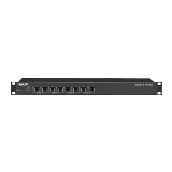
Express 8-Port Mux
1
0
LIN K
2X
•
2X
STA TU S
•
TX
RX
PO WE R
G RO UP A
CUSTOMER
SUPPORT
INFORMATION
5
4
3
2X
•
2
2X
•
2X
•
2X
•
G RO UP C
G RO UP B
Order toll-free in the U.S.: Call 877-877-BBOX (outside U.S. call 724-746-5500)
FREE technical support 24 hours a day, 7 days a week: Call 724-746-5500 or fax 724-746-0746
Mailing address: Black Box Corporation, 1000 Park Drive, Lawrence, PA 15055-1018
Web site: www.blackbox.com • E-mail: info@blackbox.com
7
6
2X
•
2X
•
G RO UP D
JUNE 2000
IC219A
rt M u x
E x p re s s 8 P o
Advertisement
Table of Contents

Related Manuals for Black Box Express 8-Port Mux


Summary of Contents for Black Box Express 8-Port Mux
- Page 1 Order toll-free in the U.S.: Call 877-877-BBOX (outside U.S. call 724-746-5500) FREE technical support 24 hours a day, 7 days a week: Call 724-746-5500 or fax 724-746-0746 SUPPORT Mailing address: Black Box Corporation, 1000 Park Drive, Lawrence, PA 15055-1018 INFORMATION Web site: www.blackbox.com • E-mail: info@blackbox.com...
- Page 2 EXPRESS 8-PORT MUX FEDERAL COMMUNICATIONS COMMISSION INDUSTRY CANADA RADIO FREQUENCY INTERFERENCE STATEMENTS This equipment generates, uses, and can radiate radio frequency energy and if not installed and used properly, that is, in strict accordance with the manufacturer’s instructions, may cause interference to radio communication.
-
Page 3: Classification Of Led Transmitter Device
Classification of LED Transmitter Device The optical transmitter contains an LED system and is classified “CLASS 1 LED PRODUCT” per EN60825-1 (+A11), Safety of Laser Products. Contact Black Box Corporation for repair if your Express 8-Port Mux ever requires maintenance. - Page 4 EXPRESS 8-PORT MUX TRADEMARKS USED IN THIS MANUAL ST is a registered trademark of AT&T. AS/400 and IBM are registered trademarks of International Business Machines Corporation. Any other trademarks mentioned in this manual are acknowledged to be the property of the trademark owners.
-
Page 5: Table Of Contents
3.2 Configuration Switch Settings .........................9 3.3 Mode Description............................10 3.4 Collapsed Rings ..............................11 3.5 Connections ..............................11 4. Installation ................................14 4.1 Host-Side Multiplexor Installation ........................14 4.2 Device-Side Multiplexor Installation......................15 5. Troubleshooting ..............................16 5.1 Possible Problems ............................16 5.2 Calling Black Box ............................18 5.3 Shipping and Packaging ..........................18... -
Page 6: Specifications
EXPRESS 8-PORT MUX 1. Specifications Active Pair: Port configurable Fiber Optic Budget: 12 dB, typical Input Impedance: 100 ohms, nominal Maximum Distance: Host to mux: 2000 ft. (609.6 m); Mux to device: 2200 ft. (670.5 m); Mux to mux: 6600 ft. -
Page 7: Introduction
EXPRESS 8-PORT MUX 2. Introduction This users’ manual applies to the Express 8-Port Mux, which is used with the IBM 5250 protocol. The 5250 family of products consists of IBM System 34, 36, 38, and the AS/400 ® , along with many supporting devices manufactured by IBM and other companies. -
Page 8: Connectors And Indicators
Figure 2-2. The Express 8-Port Mux’s Rear Panel. Power LED On when the Express 8-Port Mux is powered up. On when a signal is transmitted to the fiber optic aggregate link. TX Activity LED RX Activity LED On when a signal is received from the fiber optic aggregate link and the Mux synchronizes to it. -
Page 9: Configuration
3.1 Active Pair Setup Each Express 8-Port Mux is factory configured per customer request. The factory setting is circled on the identification label located on the rear panel. (Refer to Figure 2-2 to locate the identification label.) The active pair may be re-configured by performing the following procedure: ·... -
Page 10: Configuration Switch Settings
EXPRESS 8-PORT MUX Note that connections to the DB25 and RJ-45 connectors are mutually exclusive. If any of the three pairs of the RJ-45 connectors are selected, the DB25 is disconnected. If the DB25 is selected, the RJ-45 connectors are disconnected. -
Page 11: Mode Description
EXPRESS 8-PORT MUX 3.3 Mode Description A point-to-point link is made up of two multiplexors connected by a single backbone (see the illustration below). HOST PORT DEVICE FIBER OPTIC BACKBONE CONNECTIONS CONNECTIONS MULTIPLEXOR MULTIPLEXOR When multiple multiplexors are connected in series with fiber optic transmit to fiber optic receive, they form a ring topology (see the illustration below). -
Page 12: Collapsed Rings
EXPRESS 8-PORT MUX 3.4 Collapsed Rings The ring mode shown in Section 3.3 is seldom implemented. Instead fiber optic cables usually star out from a central location. Therefore, a ring is created by interconnecting the fiber optic star segments at the central location. - Page 13 Balun and T cable STP cable Wall plate Mini Twinax Balun (IC067A) Figure 3-3. AS/400 Twinax Brick Detail. To AS/400 WSC To Express 8-Port Mux To Express 8-Port Mux Polling group #2 Polling group #1 Mini Twinax Port #0 Balun (IC067A)
- Page 14 EXPRESS 8-PORT MUX 62.5-micron multimode Express 8-Port Mux Express 8-Port Mux UTP cabling Stars Remote Controller Patch panel Balun and T cable Two 4-Port Twinax Wall plate Bricks and Mini Twinax Baluns (IC067A) Mini Twinax Balun (IC067A) Figure 3-5. Typical Remote Controller Installation.
-
Page 15: Installation
(WSCs) have two polling groups. Ports 0 through 3 and ports 4 through 7 constitute the two groups. The Express 8-Port Mux can accommodate two polling in the same fashion. Do not connect more than one host polling group to an Express 8-Port Mux polling group. Connect the host ports to the Express 8-Port Mux ports. -
Page 16: Device-Side Multiplexor Installation
Plug the other end of the AC power cord into a properly wired outlet. All data and mode LEDs on the Express 8-Port Mux will activate for two seconds and fade off. The amber power LED on the front panel, the green power LED on the top of the external power supply, and the TX LED will activate and remain on. -
Page 17: Troubleshooting
EXPRESS 8-PORT MUX 5. Troubleshooting 5.1 Possible Problems If you experience problems with your Express 8-Port Mux, follow the guidelines below. 1) Collect all information relevant to this application. · Express 8-Port Mux serial numbers. · Host type and operating system software level. - Page 18 EXPRESS 8-PORT MUX A device is down or unstable. · Verify that there is one host polling group per Express 8-Port Mux polling group. · Verify that the host’s device type matches the device. · Verify that the host workstation controller’s capacity has not been exceeded.
-
Page 19: Calling Black Box
EXPRESS 8-PORT MUX 5.2 Calling Black Box If you determine that your Express 8-Port Mux is malfunctioning, do not attempt to alter or repair the unit. It contains no user-serviceable parts. Contact Black Box at 724-746-5500. Before you do, make a record of the history of the problem. We will be able to provide more efficient and accurate assistance if you have a complete description, including: •... - Page 20 © Copyright 2000. Black Box Corporation. All rights reserved. 1000 Park Drive • Lawrence, PA 15055-1018 • 724-746-5500 • Fax 724-746-0746...