Advertisement
TABLE OF CONTENTS
1 Warning -------------------------------------------------------------- 2
2 Specifications ----------------------------------------------------- 2
3 Troubleshooting Guide ----------------------------------------- 3
4 Disassembly and Assembly Instructions ---------------- 4
5 Wiring Connection Diagram ---------------------------------- 6
6 Schematic Diagram ---------------------------------------------- 6
7 Exploded View and Replacement Parts List ------------ 7
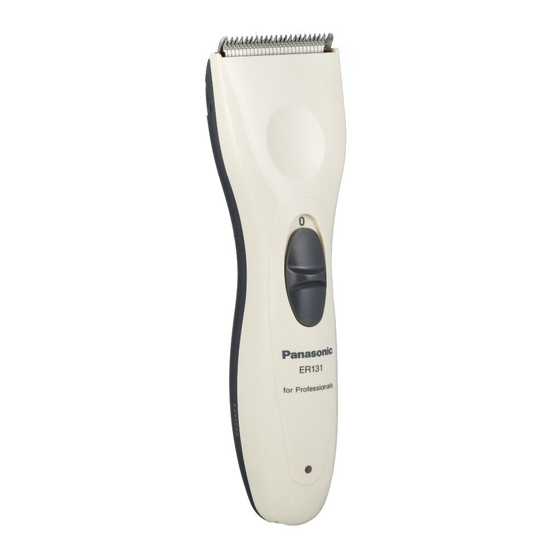
AC/Rechargeable Hair Clipper
Model No. ER131
Russia
PAGE
© 2007 Matsushita Electric Works, Ltd. All rights
reserved. Unauthorized copying and distribution is a
violation of law.
Order Number SD0704R34CE
PAGE
Advertisement

Related Manuals for Panasonic ER131


Summary of Contents for Panasonic ER131
-
Page 1: Table Of Contents
Order Number SD0704R34CE AC/Rechargeable Hair Clipper Model No. ER131 Russia TABLE OF CONTENTS PAGE PAGE 1 Warning -------------------------------------------------------------- 2 2 Specifications ----------------------------------------------------- 2 3 Troubleshooting Guide ----------------------------------------- 3 4 Disassembly and Assembly Instructions ---------------- 4 5 Wiring Connection Diagram ---------------------------------- 6... -
Page 2: Warning
1 Warning Caution: • Pb free solder has a higher melting point that standard solder; Typicall the melting point is 50 - 70°F (30 - 40°C) higher. Please use a soldering iron with temperature control and adjust it to 750 ± 20°F (400 ± 10°C). In case of using high temperature solder- ing iron, please be careful not to heat too long. -
Page 3: Troubleshooting Guide
3 Troubleshooting Guide... -
Page 4: Disassembly And Assembly Instructions
4 Disassembly and Assembly Instructions 4.1. Disassembly Instructions Follow the procedure below to disassemble the main body. 1. Remove the attachment and the blade. 2. Loosen two screws tightening the blade springs and two housing screw. 3. Separate housing A and B by opening at the blade side. 4. - Page 5 4.2. Assembly Instructions 1. Connect the motor with the lead wire. NOTE: Motor has its own direction on assembly. Place the label side on top. 2. Confirm both switch handle and switch contact block are set OFF position. Place the motor and module assembly into the Housing A.
-
Page 6: Wiring Connection Diagram
5 Wiring Connection Diagram 6 Schematic Diagram... -
Page 7: Exploded View And Replacement Parts List
7 Exploded View and Replacement Parts List 7.1. Exploded View 7.2. Replacement Parts List Safety Ref. No. Part No. Part Name & Description Quantity Remarks WER131H7399 COMB ATTACHMENT A (3/6mm) <BG> WER131H7409 COMB ATTACHMENT B (9/12mm) <BG> WER9181Y BLADE BLOCK WER850B9006 SCREW (K2-8) - Page 8 Panasonic ER131.User manual, Service manual site http:// panatex.com.ua.