
Related Manuals for Extron electronics FOXBOX Tx HDMI


Summary of Contents for Extron electronics FOXBOX Tx HDMI
- Page 1 User Guide Fiber Optic Extenders FOXBOX Tx / Rx HDMI High Resolution Fiber Optic Transmitters and Receivers 68-1984-01 Rev. B 01 18...
-
Page 2: Safety Instructions
Safety Instructions Safety Instructions • English Istruzioni di sicurezza • Italiano AVVERTENZA: Il simbolo, , se usato sul prodotto, serve ad WARNING: This symbol, ,when used on the product, is avvertire l’utente della presenza di tensione non isolata pericolosa intended to alert the user of the presence of uninsulated dangerous all’interno del contenitore del prodotto che può... - Page 3 ついては、 エクス トロンのウェブサイ ト より 『Extron Safety www.extron.com and Regulatory Compliance Guide』 (P/N 68-290-01) をご覧ください。 Copyright © 2018 Extron Electronics. All rights reserved. Trademarks All trademarks mentioned in this guide are the properties of their respective owners. The following registered trademarks( ®...
- Page 4 FCC Class A Notice This equipment has been tested and found to comply with the limits for a Class A digital device, pursuant to part 15 of the FCC rules. The Class A limits provide reasonable protection against harmful interference when the equipment is operated in a commercial environment.
- Page 5 Software Commands Commands are written in the fonts shown here: ^AR Merge Scene,,0p1 scene 1,1 ^B 51 ^W^C.0 [01] R 0004 00300 00400 00800 00600 [02] 35 [17] [03] E X! *X1** X2)* X2#* X2! NOTE: For commands and examples of computer or device responses used in this guide, the character “0”...
- Page 7 Contents Introduction Remote Control ........... 1 ........... 18 About this Guide ..........1 Simple Instruction Set Control ......18 About the FOXBOX Tx/Rx HDMI ......1 Host-to-Unit Communications ...... 18 Transmitter............2 Using the Command and Response Tables .. 20 Receiver ............
- Page 8 FOXBOX Tx/Rx HDMI • Contents viii...
-
Page 9: Introduction
Introduction WARNING: The FOXBOX Tx/Rx HDMI outputs continuous invisible light, which may be harmful to the eyes; use with caution. Le FOXBOX Tx/Rx HDMI émet une lumière invisible en continu AVERTISSEMENT : qui peut être dangereux pour les yeux, à utiliser avec précaution. •... -
Page 10: Transmitter
Typical FOXBOX Tx/Rx HDMI Application Transmitter The FOXBOX Tx HDMI transmitter accepts HDMI video or DVI-D video (with an applicable adapter), at resolutions up to 1920 x 1200 at 60 Hz. The video input can also include embedded audio. The transmitter also loops the HDMI input through for a local monitor. -
Page 11: Receiver
System Compatibility The FOXBOX Tx HDMI transmitter operates in either of two modes, selected under RS-232 control, for compatibility with other, non-HDMI, units: Plus — Support resolutions up to 1920 x 1200 @ 60 Hz. The fiber optic output of •... -
Page 12: Features
Loop-through on transmitter — The transmitter has an HDMI loop-through on a HDMI connector that allows connection of a local monitor. EDID emulation mode (Display Data Channel [DDC]) — The FOXBOX Tx HDMI • transmitter provides a selector switch for specifying the rate of the incoming digital video signal. -
Page 13: Installation
DVI-D (with the appropriate adapter) to this HDMI connector (see HDMI connector page 12). The FOXBOX Tx HDMI also accepts embedded digital audio on this connector. HDMI Loop-through connector — If desired, connect a local monitor to this HDMI connector. - Page 14 Audio connector (see figure 2 on the previous page) — Plug an audio input into the transmitter via this stereo mini jack connector. AUDIO INPUT NOTE: See figure 3 to identify the tip, ring, and sleeve when you are making connections for the transmitter from existing audio cables.
- Page 15 Fiber optic connectors and LEDs (see figure 2 on page 5)— WARNING: The FOXBOX Tx/Rx HDMI outputs continuous invisible light, which may be harmful to the eyes; use with caution. AVERTISSEMENT : Le FOXBOX Tx/Rx HDMI émet une lumière invisible en continu qui peut être dangereux pour les yeux, à...
- Page 16 See Remote Control on page 18 for SIS commands and software control. The TRS RS-232 cable is included with the FOXBOX Tx HDMI transmitter. DC power connector — Plug the included external 12 VDC power supply POWER 1.0A MAX...
-
Page 17: Receiver Connections, Controls, And Indicators
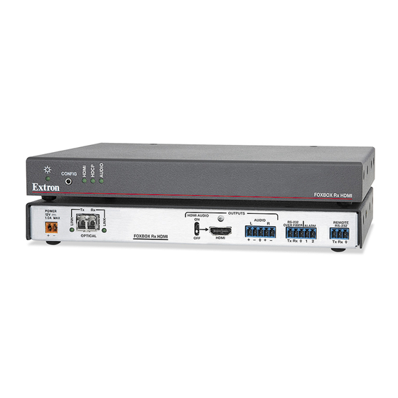
Receiver Connections, Controls, and Indicators Rear panel O O P P POWER OUTPUTS HDMI AUDIO AUDIO RS-232 REMOTE 1.0A MAX OVER FIBER ALARM RS-232 FOXBOX Rx HDMI HDMI Tx Rx Tx Rx OPTICAL Figure 4. FOXBOX Rx Receiver Rear Panel Features HDMI Input connector (see below) HDMI Loop-through Connector Audio connector... - Page 18 Fiber optic connectors and LEDs (see figure 4 on the previous page) — WARNING: The FOXBOX Tx/Rx HDMI outputs continuous invisible light, which may be harmful to the eyes; use with caution. AVERTISSEMENT : Le FOXBOX Tx/Rx HDMI émet une lumière invisible en continu qui peut être dangereux pour les yeux, à...
-
Page 19: Front Panel
Front panel Configuration ports on page 14 for more details on the adapter cable. See Remote Control on page 17 for SIS commands and software control. The TRS RS-232 cable is included with the FOXBOX Tx HDMI transmitter. FOXBOX Tx/Rx HDMI • Installation... -
Page 20: Making Connections
Making Connections HDMI connector HDMI signals run at a very high frequency and are especially prone to errors caused by bad video connections, too many adapters, or excessive cable length. To avoid the loss of an image or jitter, follow these guidelines: Do not exceed 16.4 feet (5 meters) on the input or buffered loop-through of the •... - Page 21 RS-232 connections The Remote RS-232 port on the receiver only is for remote control of the receiver. The RS-232 Over Fiber port on both units is for transmission of serial signals, such as projector control signals, between the transmitter and receiver. See figure 9 to properly wire the connectors.
- Page 22 Audio output connector See figure 11 to properly wire a captive screw output connector. The connector is included with transmitter, but you must supply the audio cable. Use the supplied tie-wrap to strap the audio cable to the extended tail of the connector. NO GROUND HERE Ring Sleeves...
-
Page 23: Power Supply Wiring
Remote Control on page 18 for definitions of the SIS commands (serial commands to control the transmitter via the Configuration port) and software control. Power supply wiring ATTENTION: • Always use a power supply provided by or specified by Extron. Use of an unauthorized power supply voids all regulatory compliance certification and may cause damage to the supply and the unit. -
Page 24: Operation
ATTENTION: • This product is intended to be supplied by a UL Listed power source marked “Class 2” or “LPS,” rated 12 VDC, 1.0 A minimum. Always use a power supply supplied by or specified by Extron. Use of an unauthorized power supply voids all regulatory compliance certification and may cause damage to the supply and the end product. -
Page 25: Troubleshooting — If No Image Appears
Troubleshooting — If No Image Appears Ensure that all devices are plugged in and powered on. The transmitter and receiver are receiving power if their power LEDs are lit. Ensure an active input is applied to the transmitter. The tranmsitter is receiving an active input if the HDMI LED is lit. -
Page 26: Remote Control
Remote Control This section includes: Simple Instruction Set Control • • FOX Extenders Control Program The transmitter and receiver each have a front panel Configuration port, a 2.5 mm mini stereo jack (see Front panel Configuration ports on page 14). The receiver has a rear panel Remote RS-232 port, a 3-pole captive screw connector (see RS-232 connections on page 13). - Page 27 When a local event, such as an equipment power-up, occurs, the unit responds by sending a message to the host. The unit-initiated messages are listed below: x.xx, c) Copyright 20 , Extron Electronics FOXBOX Tx HDMI, V 60-1174- - or - x.xx,...
-
Page 28: Using The Command And Response Tables
Error Responses When the unit receives a valid SIS command, it executes the command and sends a response to the host device. If the switcher is unable to execute the command because the command is invalid or it contains invalid parameters, the transmitter or receiver returns an error response to the host. -
Page 29: Switch Mode
Command and Response Table for Transmitter SIS Commands SIS Command Response Additional description Command Function (Host to Unit) (Unit to Host) Switch status Request EDID and refresh rate Stat EdidMdr •Vrate switch positions Example EDID switch is set to 15 (1080p) and the Stat didMdr15•... - Page 30 Command and Response Table for Transmitter SIS Commands (continued) SIS Command Response Additional description Command Function (Host to Unit) (Unit to Host) Switch mode (continued) Show native EDID value Show the native resolution of the NEDID display connected to the receiver. Import EDID 0EDID EdidI...
-
Page 31: Status Requests
Command and Response Table for Transmitter SIS Commands (continued) SIS Command Response Additional description Command Function (Host to Unit) (Unit to Host) Status requests X1@] View link 1 (Tx-to-Rx) status X1@] View link 2 (Rx-to-Tx) status X1@] View input video status X1@] View input audio status X1@]... - Page 32 Symbol definitions for receiver SIS commands = Carriage return/line feed = Carriage return (no line feed) = Pipe (can be used interchangeably with the character) • = Space (hard) character = Escape key (hex 1B) = Can be used interchangeably with the character = Mute/auto memory status and enable or disable status = off or disable...
- Page 33 Command and Response Table for Receiver SIS Commands (continued) SIS Command Response Additional description Command Function (Host to Unit) (Unit to Host) Memory presets X1(] Save preset Command code is a comma. X1(] Recall preset Command code is a period. Auto memory Disable auto memory 55*0#...
- Page 34 Command and Response Table for Receiver SIS Commands (continued) SIS Command Response Additional description Command Function (Host to Unit) (Unit to Host) Video shutdown delay NOTES: • The Set Video Delay command delays the digital video to help monitors sync correctly during an input rate change. •...
-
Page 35: Information Requests
Command and Response Table for Receiver SIS Commands (continued) SIS Command Response Additional description Command Function (Host to Unit) (Unit to Host) Information requests Information request • • • • • 1Lnk 2Lnk The unit responds with the current status (signal detected) of optical link 1, optical link 2, the video input, and the audio link;... -
Page 36: Fox Extenders Control Program
FOX Extenders Control Program The Extron FOX Extenders program, which communicates with the transmitter and receiver pair via the Remote RS-232 port of either unit provides an easy way to operate the pair. The program is compatible with Windows 2000, Windows XP, or later. This software and updates to it can be downloaded from the Extron Web site (www.extron.com). -
Page 37: Starting The Program
Follow the instructions that appear on the screen. By default, the installation creates a directory, and it places four icons into a Program Files Extron Extenders group folder named “ ” The four Extron Electronics FOX Extender Control Program installed icons are: Check for FOX Extenders updates • FOX Extenders •... - Page 38 Figure 18. FOX Extenders Control Program Window NOTES: • Figure 16 is an amalgam of program displays. Some controls and displays are available when connected to the transmitter only and some when connected to the receiver only. These functions are identified in the descriptions that follow. •...
-
Page 39: Using The Program
Using the Program Status panel Figure 19. Status Panel panel provides indications of the connection status. Status • HDMI indicator — This indicator is green when the transmitter detects a sync signal on its HDMI video input • Audio indicator — This indicator is green when the transmitter detects a low level audio signal for a short period. - Page 40 Control tab functions Click the tab to access the picture and audio adjustments functions described Control below. Figure 20. Control Tab Video Adjustment panel NOTE: The panel controls are available only Video Adjustment if you are connected to the receiver and an active video input is connected to the transmitter.
- Page 41 Mute panel NOTE: The panel controls are available only if you are Mute connected to the receiver. Click the radio button, the radio button, or both in the panel Video Mute Audio Mute Mute to turn the video and audio mutes on and off. I/O Configuration tab functions Click the tab to access the functions described below.
- Page 42 Plus Mode Transmission panel NOTE: The radio buttons are available Plus Mode Transmission only if you are connected to the transmitter. radio buttons allow you to enable and disable Plus mode. Plus Mode Transmission Plus mode enabled forces the transmitter to emulate a FOXBOX DVI Plus or PowerCage FOX DVI Plus transmitter for compatibility with one of four receivers: a FOXBOX HDMI Rx, a FOXBOX DVI Plus Rx, a PowerCage HDMI Rx, or a PowerCage FOX DVI Plus Rx.
- Page 43 Auto Memory radio buttons Select the radio button to automatically apply saved position Auto Memory settings when the sensed input resolution changes. Test Patterns drop box Select one of three built-in test patterns; , and Colorbars Grayscale ; as necessary to help adjust the color, brightness, Alternating Pixels contrast, and focus of the display.
- Page 44 Assigned EDID panel NOTES: • panel control is available only if you Assigned EDID are connected to the transmitter and the transmitter front panel EDID Minder hex switch is in position 1. If the hex switch is not in position 1, the Assigned EDID panel advises you “...
- Page 45 Export EDID panel EDID files on the FOX Tx HDMI can be exported to the connected PC. To open and view them, use the Extron EDID Manager software, available at www.extron.com. The EDID Manager software aids in troubleshooting any EDID related issues that may occur during configuration or operation of an AV system.
-
Page 46: Updating The Firmware
Updating the Firmware Firmware can be updated for each unit via the front panel Configuration port on that unit using the Extron Firmware Loader utility from the Windows-based control program. NOTES: • There are different files for the transmitter (Tx) and receiver (Rx). •... - Page 47 1 1 1 1 1 1 1 1 2 2 2 2 2 2 2 2 3 3 3 3 3 3 3 3 Folder where firmware is saved. 4 4 4 4 4 4 4 4 Figure 27. Extracting Firmware Upgrade Files FOXBOX Tx/Rx HDMI •...
- Page 48 Ensure that: The computer is connected to the front panel Configuration port (see item • item page 8) or top panel Configuration port (see on page 11) of the unit to be updated. The FOX Extenders Control Program is running. •...
- Page 49 2 2 2 2 2 2 2 2 1 1 1 1 1 1 1 1 Figure 29. Extron Firmware Loader Window Select the FOXBOX unit ( Click > ). The screen appears (see figure 30). File Open Choose Firmware File 1 1 1 1 1 1 1 1 2 2 2 2...
-
Page 50: Equipment Mounting
Equipment Mounting This section provides procedures for mounting the transmitter and receiver. Mounting the Unit ATTENTION: • Installation and service must be performed by authorized personnel only. • L’installation et l’entretien doivent être effectués par le personnel autorisé uniquement. Either of the 1-inch high, quarter-rack width (transmitter) or half-rack width (receiver) units can be placed on a tabletop, mounted on a rack shelf, or mounted under or through a desk or other furniture. - Page 51 Extron Electronics makes no further warranties either expressed or implied with respect to the product and its quality, performance, merchantability, or fitness for any particular use. In no event will Extron Electronics be liable for direct, indirect, or consequential damages resulting from any defect in this product even if Extron Electronics has been advised of such damage.