Table of Contents
Advertisement
Advertisement
Table of Contents

Related Manuals for Motorola NNTN7624


Summary of Contents for Motorola NNTN7624
- Page 1 VEHICULAR CHARGER (IMPRES Compatible System) NNTN7624 User Guide...
- Page 2 blank.fm Page 1 Thursday, October 14, 2010 3:18 PM...
-
Page 3: Safety And General Information
Product Safety and RF Exposure Compliance Before using this product, read the operating instructions for safe usage contained in the “Product Safety and RF Exposure Booklet” enclosed with your radio, (Motorola publication number 6881095C98 and 6864117B25) to ensure compliance with RF energy exposure limits. -
Page 4: Operational Warnings
“Turn off two-way radio.” Obey all signs and instructions. Operational Cautions Efficient System Operation • All equipment must be properly grounded according to Motorola installation instructions for safe operation. All equipment should be serviced only by an authorized technician. - Page 5 68009297001-B_Text.fm Page 3 Thursday, December 10, 2015 1:40 PM About the Vehicular Charger The NNTN7624 Vehicular Charger kit is used for charging a radio (or battery alone) when inside a vehicle. The Vehicular Charger kit includes a mounting bracket (to mount the unit inside the vehicle) and wire harness.
- Page 6 68009297001-B_Text.fm Page 4 Thursday, December 10, 2015 1:40 PM A radio can be operated while in the charger, but this will prolong the amount of time needed to fully charge the battery. Note: Excessive use of a radio while it is in the charger will cause its battery to become discharged.
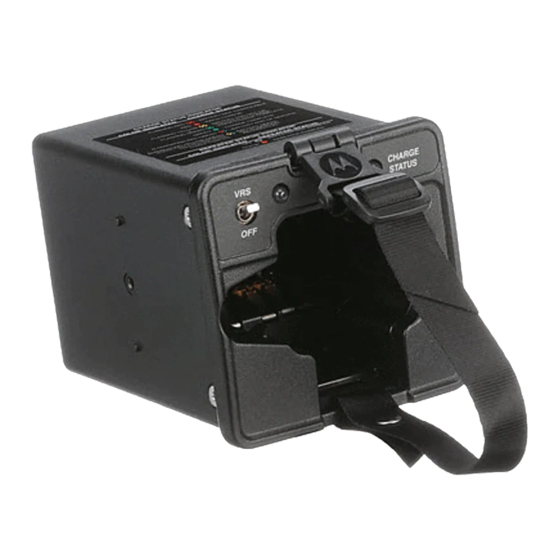
- Page 7 68009297001-B_Text.fm Page 5 Thursday, December 10, 2015 1:40 PM Getting to Know Your Vehicular Charger Note: Repeater (VRS) Status LED and Repeater (VRS) Status Toggle are only used when there is a repeater. Programming Port - Programming via RJ11 - Future Use RLN5671 Field (Display Module) Programmer...
- Page 8 68009297001-B_Text.fm Page 6 Thursday, December 10, 2015 1:40 PM Guide Pins - help alignment within the U-Bracket or trunnion Strap System secures radio and/ or battery in the pocket. Lock - locks the vehicular charger within the U-Bracket (is secured with the use of #10 star washers and thumbscrews.
- Page 9 68009297001-B_Text.fm Page 7 Thursday, December 10, 2015 1:40 PM A properly installed unit will minimize service calls and equipment downtime. Consider the following guidelines when planning the installation: • DO consider a mounting location which will allow the unit to be mounted at a 45- degree up angle.
- Page 10 68009297001-B_Text.fm Page 8 Thursday, December 10, 2015 1:40 PM Figure 1 .Installing the Vehicular Charger Referring to Table 1 and Figure 2, connect the red (A+) wire (with the inline fuse) of the supplied cable to either an unswitched terminal on the vehicle’s fuse box or directly to the positive (+) terminal of the vehicle’s battery.
- Page 11 68009297001-B_Text.fm Page 9 Thursday, December 10, 2015 1:40 PM Important Note: If a vehicular repeater is installed, verify operation of the repeater before leaving the vicinity of the vehicle. 13.8 VOLT VEHICLE BATTERY 2-AMP GROMMET INLINE FUSE FIREWALL OPTIONAL 0.25-AMP INLINE FUSE YELLOW FUSE...
- Page 12 68009297001-B_Text.fm Page 10 Thursday, December 10, 2015 1:40 PM Signal Color Fuse 2A 250V Fuse 2A 250V Repeater (VRS) PAC - RT White Fuse 0.25A 250V Fuse .5A 250A Ignition Sense Yellow Black 36”(914 mm) 21” (533 mm) Pin 6 Pin 4 16”(406 mm) Pin 2...
- Page 13 68009297001-B_Text.fm Page 11 Thursday, December 10, 2015 1:40 PM Securing the Radio in the Vehicular Charger The NNTN7616 Vehicular Charger is equipped with a feature that reduces the risk of a portable radio (or battery alone) in the pocket from becoming dislodged and potentially hazardous in the event of a vehicular collision.
- Page 14 68009297001-B_Text.fm Page 12 Thursday, December 10, 2015 1:40 PM For radios with an antenna installed, loop the strap between the base of the antenna and base of the channel selector, and then engage the latch onto the Top Engagement Bar on the Faceplate. Adjust the strap through the Tri-Glide to secure radio with battery attached within the Vehicular Charger (refer to Figure 4).
- Page 15 68009297001-B_Text.fm Page 13 Thursday, December 10, 2015 1:40 PM Figure 5 .Ni-Battery without Radio For charging lithium battery, NNTN7038, that is not attached to a radio, engage the battery onto the adapter (refer to Figure 6) before inserting into the charger Figure 6.
- Page 16 68009297001-B_Text.fm Page 14 Thursday, December 10, 2015 1:40 PM Operating the Vehicular Charger Never place any objects other than a radio and/or battery into the charger pocket — this could damage the charger! Please avoid contact (direct or incidental) with the heatsink. W A R N I N G Operation of the charger is automatic.
- Page 17 68009297001-B_Text.fm Page 15 Thursday, December 10, 2015 1:40 PM LED indicators on the front panel of the charger indicate charger status: BATTERY CHARGE STATUS INDICATION LED INDICATOR CHARGE STATUS Battery is not chargeable or not making proper contact. BLINKING RED Battery is in rapid charge mode or in charge recovery due to low voltage battery.
-
Page 18: Specifications
7.4 Vtyp @ 13.6 V input Warranty Replacement Motorola, Inc. (“Motorola”) warrants the Vehicular Charger against defects in material and workmanship under normal use and service for a period of one (1) year from shipment. Items will be repaired or replaced free of charge for the full warranty period. - Page 19 blank.fm Page 1 Thursday, October 14, 2010 3:18 PM...
- Page 20 68009297001-B_back.fm Page 1 Tuesday, December 8, 2015 10:18 AM © 2009 and 2015 by Motorola Solutions Inc. Motorola, APX and IMPRES are registered trademarks of Motorola Solutions, Inc. All other product or service names are the property of their respective owners.