Table of Contents
Advertisement
Advertisement
Table of Contents

Related Manuals for Aztech DSL605EW


![Wireless Router Aztech [17:34:06] ?????????? ???????: HomePlug AV 200Mbps 4-Port Wireless-N Router User Manual](https://static-data2.manualslib.com/product-images/f6d/552196/60x60/aztech-17-34-06-homeplug-av-200mbps-4-port-wireless-n-router-wireless-router.jpg)


Summary of Contents for Aztech DSL605EW
- Page 1 Ethernet Wireless Router User Manual VERSION 0.1...
- Page 2 User Manual Safety Precautions Do not open, service, or change any component. Only qualified technical specialists are allowed to service the equipment. Observe safety precautions to avoid electric shock Check voltage before connecting to the power supply. Connecting to the wrong voltage will damage the equipment.
-
Page 3: Table Of Contents
User Manual Contents About this Manual ............6 Scope and Purpose ...................6 Target Audience ..................6 Document Structure .................6 About the Router............7 Requirements...................7 Software.............................7 Hardware ...........................7 Package Contents..................8 Device Design...................9 Front Panel..........................9 Back Panel ..........................10 Planning Your Network ................11 Installing the Router ................12 Connecting with the POTS Splitter..................12 Connecting with the Computer....................13 Connecting Other Ethernet Devices..................14... - Page 4 User Manual Status Menu ...................22 Help Menu....................23 Setup ................24 Remove or Disable Conflicts..............24 Internet Sharing, Proxy, and Security Applications ...............24 Configuring TCP/IP Settings....................25 Configuring Internet Properties ....................25 Removing Temporary Internet Files..................26 Using the Setup Menu ................27 Setting Up Via the Utility Wizard ....................32 Setting the Administrator Account............33 Changing the System Password .....................33 Changing the Timeout Settings ....................33...
- Page 5 User Manual DNS Proxy ..........................75 Dynamic DNS Client.........................76 Easy Connect Configuration ....................77 Port Triggering.........................78 Port Forwarding........................79 Bridge Filters..........................81 Web Access Control .........................82 SSH Access Control ........................83 Quality of Service ...................84 Egress ............................86 Ingress............................89 QoS Shaper Configuration .......................95 Policy Routing Configuration ....................99 Routing ....................102 Static Routing........................
-
Page 6: About This Manual
User Manual About this Manual This manual provides a description of the components, basic operation, and advanced configuration options of the router. Scope and Purpose This manual provides the following: Installation instructions Description of the router components and the web interface Operating instructions of the router and the web interface Target Audience This manual is designed and developed for users who are required to install and maintain... -
Page 7: About The Router
User Manual About the Router Congratulations on the purchase of your router. This router provides advanced features that allow you to converge your phone, Internet, and other network appliances into a single network either through wired or wireless connection. Requirements Your computer must meet the following minimum requirements. -
Page 8: Package Contents
User Manual Package Contents For any missing items, please contact your dealer immediately. Product contents vary for different models. Package Contents Page 8 of 118... -
Page 9: Device Design
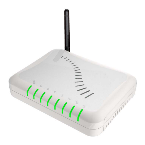
User Manual Device Design Front Panel The LEDs on the front panel gives you an idea about the power and connection status. Label Action Description POWER No power is supplied to the device Steady light Connected to an AC power supply ETHERNET No Ethernet connection Steady light... -
Page 10: Back Panel
User Manual Blinking light Transmitting/Receiving data No DSL signal Blinking light Establishing DSL signal Steady light DSL signal is established INTERNET No Internet connection Steady light Connected to the Internet Blinking light Transmitting/Receiving data Back Panel The back panel provides ports to power up and connect the router into the network. Back Panel Label Used for…... -
Page 11: Planning Your Network
User Manual Planning Your Network Before moving ahead to setup your network, it is a good idea to draw out a network diagram to help identify the devices and plan out how to connect these devices. The illustration below is an example of a network diagram. Sample network diagram To create a network diagram: For wireless devices, identify the wireless devices you want to include in the... -
Page 12: Installing The Router
User Manual Installing the Router When installing the router, the common practice is to have the router, the main computer, and phone jack in the same room. The room should also have enough electrical outlets to match your needs. Connecting with the POTS Splitter A phone line can carry phone call and Internet signals. -
Page 13: Connecting With The Computer
User Manual Connecting with the Computer You need to connect the router with the computer before connecting with other devices. The computer will be used to configure the router settings. Connecting the router with the computer To connect with the computer: 1. -
Page 14: Connecting Other Ethernet Devices
User Manual Connecting Other Ethernet Devices Aside from the main computer, you can grow your network by adding devices with Ethernet ports. Connect these devices into available Ethernet ports on the router. Connecting other devices To the connect with other devices: 1. -
Page 15: Connecting Wireless Devices
User Manual Connecting Wireless Devices After you setup the device settings through the main computer, you can connect other devices with wireless capabilities. Wireless devices relieve you from the task of laying out cables and allow you to use the Internet connection from your router. Your router allows you to connect with several wireless devices To the connect with wireless devices: 1. -
Page 16: Understanding The Web Interface
User Manual Understanding the Web Interface Web Interface Components Buttons, commands, and menus make up the browser-based user interface. Buttons Apply Click to implement the configuration changes. Clicking Apply will not implement the changes when the router is restarted. Cancel Click to revert to the last saved configuration. -
Page 17: Setup Menu
User Manual Wireless Menu Security Menu Status Menu Help Menu Setup Menu The Setup menu is used to complete the initial device configuration. Setup Menu Page 17 of 118... -
Page 18: Basic Menu
User Manual Basic Menu The Basic Menu provides the Home, Quick Start, LAN Configuration, and Diagnostics links. Basic Menu Page 18 of 118... -
Page 19: Advanced Menu
User Manual Advanced Menu The Advanced mode provides advanced configuration settings for existing connections. At least one WAN connection must be configured before implementing advanced WAN configuration features. At least one LAN group must be defined before implementing advanced LAN configuration features. Advanced Menu Page 19 of 118... -
Page 20: Wireless Menu
User Manual Wireless Menu Wireless Menu allows you to configure the wireless settings. Page 20 of 118... -
Page 21: Security Menu
User Manual Security Menu Security Menu allows you to configure security tools like IP Filters and LAN Isolation. Security Menu Page 21 of 118... -
Page 22: Status Menu
User Manual Status Menu The Status Menu provides the status for different connections or interfaces. Status Menu Page 22 of 118... -
Page 23: Help Menu
User Manual Help Menu The Help Menu provides documentation about various router features. Help Menu Page 23 of 118... -
Page 24: Setup
User Manual Setup This chapter provides information about removing conflicts and configuring device settings. Remove or Disable Conflicts To make sure the router installation moves on smoothly, you need to remove or disable conflicts that may interfere the installation. Probable conflicts may include: Internet sharing applications Proxy software Security software... -
Page 25: Configuring Tcp/Ip Settings
User Manual Configuring TCP/IP Settings After connecting the device, you need to set the TCP/IP Properties in your computer. Note: These instructions apply to connections made using the Ethernet port. To set the TCP/IP properties: 1. Select Start > Run. This opens the Run dialog box. 2. -
Page 26: Removing Temporary Internet Files
User Manual Removing Temporary Internet Files To remove temporary Internet files: 1. Select Start > Run. This opens the Run dialog box. 2. Enter control and then click OK. This opens the Control Panel. 3. Double-click Internet Options. This opens the Internet Options dialog box. 4. -
Page 27: Using The Setup Menu
User Manual Using the Setup Menu After connecting the devices, you need to configure the router settings via the web interface. To open the web interface: 1. Open your browser. 2. Enter 192.168.1.1 in the address field and then press Enter. This opens the Setup page of the web interface. - Page 28 User Manual 3. Click Step 1: Internet Login Account Setting. This opens the Internet Login Account Setting page. Internet Login Account Setting page 4. Enter the User ID, Password, Protocol, VP1, and VCI for your account. These are the account information from your service provider. 5.
- Page 29 User Manual Wireless LAN Configuration page 6. Enter an SSID, Country Standard, and Wireless Channel. 7. Select Yes or No to specify if you want to hide your wireless network name or not. 8. Click Next. This opens the Wireless LAN Security page. Wireless LAN Security 9.
- Page 30 User Manual 10. Enter an Encryption Key or click Generate to allow the router to create an alphanumeric encryption key for you. The Encryption key will be used to establish the wireless network connection of wireless devices. Page 30 of 118...
- Page 31 User Manual 11. Click Next. This opens the System Password page. System Password page 12. Select Enable Authentication. 13. Enter User Name, Password, and Confirm Password. 14. Enter the number of minutes for Idle Timeout. 15. Click Next. This opens the Summary page. 16.
-
Page 32: Setting Up Via The Utility Wizard
User Manual 17. This opens a dialog box asking if you want to save and restart the router. Click OK. The router will take about two minutes to save the settings and establish a connection with your Internet service provider. Afterwards, the Basic Home page opens to give you a summary of the account settings. -
Page 33: Setting The Administrator Account
User Manual Setting the Administrator Account Anyone who can access the web interface can be considered an Administrator. To restrict access to the web interface, you need to set the System Password. Changing the System Password To change the System Password: 1. -
Page 34: Network Setup
User Manual 6. To make changes permanent, click Save Settings. Network Setup There are two types of network configuration for your router: WAN setup and LAN setup. WAN Setup Wide Area Network (WAN) is also referred to as the broadband connection. Connection settings differ for every service provider. - Page 35 User Manual Bridge Connection CLIP Connection PPPoE Connection PPP, or point-to-point protocol, is a method of establishing a network connection/session between network hosts. PPPoE is a protocol for encapsulating PPP frames in Ethernet frames and is described in RFC 2516. PPPoE provides the ability to connect to a network of hosts over a simple bridging access device to a remote access concentrator.
- Page 36 User Manual PPPoA Connection PPPoA is also known as RFC 2364. It is a method of encapsulating PPP packets in ATM cells that are carried over the DSL line. PPP, or point-to-point protocol, is a method of establishing a network connection/session between network hosts. It usually provides a mechanism of authenticating users.
- Page 37 User Manual Static Connection Static connection type is used whenever a known static IP address is assigned to the router. Additional addressing information such as the subnet mask and the default gateway must also be specified. Up to three domain name server (DNS) addresses can be identified.
- Page 38 User Manual DHCP Connection DHCP allows the router to automatically obtain the IP address from the server. This option is commonly used in when the IP is dynamically assigned and is not known prior to assignment. New DHCP Connection Setup Page 38 of 118...
- Page 39 User Manual Bridge Connection A pure bridged connection does not assign any IP address to the WAN interface. NAT and firewall rules are not enabled. This connection method makes the router act as a bridge for passing packets between the WAN interface and the LAN interface. New Bridge Connection Setup Page 39 of 118...
- Page 40 User Manual CLIP Connection Classical IP over ATM (CLIP) Connection Setup page (CLIP) provides the ability to transmit IP packets over an ATM network. CLIP support encapsulates an IP datagram in an AAL5 PDU frame using RFC 2225 and it uses an ATM-aware version of the address resolution protocol (ATMARP).
- Page 41 User Manual ADSL Modulation ADSL Modulation allows you to select any combination of DSL training modes. Leave the default value if you are unsure or the service provider did not provide this information. In most cases, this screen should not be modified. ADSL Modulation Page 41 of 118...
- Page 42 User Manual Connection Scan This feature helps users to detect the PVC settings provided by the service provider. Before the router can begin scanning the connection, the telephone line has to be plugged into the router. Connection Scan To perform connections scan: 1.
-
Page 43: Lan Setup
User Manual LAN Setup The router is preconfigured to automatically provide IP addresses to all the computers in the Local Area Network (LAN). Your router allows you to create and configure LAN groups. LAN Configuration Your router’s default IP address and subnet mask are 192.168.1.1 and 255.255.255.0, respectively. - Page 44 User Manual To configure the LAN groupings: 1. Select the Advanced Menu. 2. Select LAN > LAN Configuration. 3. Select ETHERNET in LAN group 1 and then click < Remove. No packets will be sent to the ETHERNET interface because it does not belong to any LAN group. 4.
- Page 45 User Manual LAN Group Configuration LAN Group Configuration allows you to configure settings for each LAN group. Notice that you can also view the status of advanced services that can be applied to a LAN group. Green indicates that the service is enabled, while red indicates that the service is disabled.
- Page 46 User Manual PPP IP Address Enables/disables PPP unnumbered feature. IP Address The IP address should be different but within the same subnet as the WAN-side IP address. Use the following Static IP This field enables you to change the IP address of the address router.
- Page 47 User Manual with the router if your host has DHCP enabled. End IP The End IP Address is where the DHCP server stops issuing IP addresses. The ending address cannot exceed a subnet limit of 254; hence the max value for the default gateway is 192.168.1.254.
- Page 48 User Manual Assign ISP DNS, SNTP When you enable the DHCP server, the router dynamically assigns IP addresses to computers in the local network. The router provides its own LAN IP address (192.168.1.1) as both the gateway and the DNS server. The router has a choice of advertising its own IP address (192.168.1.1) as the DNS server or providing the DNS that was received from the WAN.
- Page 49 User Manual To add LAN Clients: 1. Select Advanced Menu. 2. Select LAN > LAN Clients. This opens the LAN Clients page. 3. Select a LAN Connection, and enter IP Address, Hostname, and MAC Address. 4. Click Apply. 5. You can convert the dynamic into a static entry by clicking Reserve, and then click Apply.
-
Page 50: Wireless Setup
User Manual Wireless Setup The SSID default is yournetworkname. SSID is wireless network name for the wireless router. Your wireless client needs this name to establish wireless connection. The wireless setup allows the user to enable or disable the Access Point (AP). Disabling Access Point will prevent the wireless router from emitting any wireless signal. -
Page 51: Wireless Configuration
User Manual Wireless Configuration For users who want to explore the advanced features, you can click on the Advanced button. The options listed can be changed to cater for advance users. Wireless Configuration To access Wireless Setup: 1. Select the Wireless Menu. 2. -
Page 52: Multiple Ssid
User Manual Multiple SSID Multiple SSID allows you to use a primary and a secondary SSID. The SSID field takes up to 32 alphanumeric characters. Change the VLAN ID to a number different from zero (between 1 to 4095). Multiple SSID To access Wireless Setup: 1. -
Page 53: Wireless Security
User Manual Wireless Security It is important for user to enforce security in wireless LAN environment. This is to prevent unauthorized wireless users from accessing your router. By default, None is selected. Wireless Security WEP is a security protocol for WLAN. WEP provides security by encrypting the data that is sent over the WLAN. - Page 54 User Manual With WEP, the receiving station must use the same key for decryption. Each radio network interface card (NIC) and router must be manually to use the same key. Wireless Security - WEP To configure WEP: 1. Select the Wireless Menu. 2.
- Page 55 User Manual 802.1x 802.1x is a security protocol for WLAN. It is a port-based network access control that keeps the network port disconnected until authentication is completed. 802.1x is based on extensible authentication protocol (EAP). EAP messages from the authenticator to the authentication server typically use the remote authentication dial-in user service (RADIUS) protocol.
- Page 56 User Manual WPA is the short term for WiFi Protected Access. WPA is an industry-supported, pre- standard version of 802.11i that utilizes the Temporal Key Integrity Protocol (TKIP), which fixes the problems of WEP, which includes using dynamic keys. WPA uses a sophisticated key hierarchy that generates new encryption keys each time a mobile device establishes itself with an Access Point.
-
Page 57: Wireless Management
User Manual Wireless Management The wireless management function gives another level of security to your router. It allows you to permit or ban devices by entering the MAC address or selecting devices that are currently connected. Access List This feature permits you to permit or ban wireless clients by using the MAC address. Wireless Management –... - Page 58 User Manual Associated Stations Clients connected to the wireless router are displayed in this page. Wireless Management – Associated Stations To permit or ban a client through the Access List page: 1. Select the Wireless Menu. 2. Select Wireless Management. This opens the Wireless Management page. 3.
- Page 59 User Manual Wireless Distribution System Wireless distribution system (WDS) is a system that interconnects BSS to build a premise wide network. WDS network allows users of mobile equipment to roam and stay connected to the available network resources. Wireless Distribution System Field Description WDS Mode...
- Page 60 User Manual Secret The 32-character alphanumeric privacy key. Auto Channel Auto channel selection is not supported in the current version. Selection Auto Auto configuration is not supported in the current version. Configuration Uplink The BSS ID of the upper device in the WDS hierarchy. This uplink cannot be Connection configured if root is enabled.
-
Page 61: Security Settings
User Manual Security Settings Configuring IP Filters IP filtering allows you to block specific applications/services based on the IP address of the LAN device. In this page, you can block specific traffic (for example, block web access) or any traffic from a host on your local network. A database of predefined IP filters allows you to apply one or more filtering rules to one or more members of a defined LAN group. -
Page 62: Lan Isolation
User Manual 4. If a rule is not in the list, you can create your own rule in the User category. Select User, and then click New. 5. The Rule Management page opens for you to create new rules. Enter Rule Name, Protocol, Port Start, Port End, and Port Map, and then click Apply. -
Page 63: Url Filters
User Manual 2. On the LAN Isolation page, select the checkbox for Disable traffic between LAN group 1 and LAN group 2. 3. To temporarily implement the changes, click Apply. 4. To make changes permanent, click Save Settings. URL Filters URL Filtering allows the router to block access to certain websites by examining its URL, a text string describing a unique location on the Internet. -
Page 64: Help
User Manual Help The Help page provides documentation for various topics like Firewall, Bridge Filters, LAN Clients, LAN Group Configuration, PPP Configuration, UPnP, IP QoS, and Routing Information Protocol. To access Help, select the Help Menu. Help Page 64 of 118... -
Page 65: Advanced Settings
User Manual Advanced Settings This chapter provides advanced configuration options for your router. Applications Applications include: Universal Plug and Play (UPnP) Simple Network Timing Protocol (SNTP) Simple Network Management Protocol Internet Group Management Protocol (IGMP) Proxy TR-068 WAN Access TR-069 NAT Services DNS Proxy Dynamic DNS Client... -
Page 66: Universal Plug And Play
User Manual Universal Plug and Play Universal plug and play (UPnP), NAT, and firewall traversal allow traffic to pass through the router for applications using the UPnP protocol. This feature requires one active WAN connection. In addition, the computer should support this feature. In the presence of multiple WAN connections, select a connection on which the incoming traffic is present, for example, the default WAN connection. -
Page 67: Simple Network Timing Protocol
User Manual Simple Network Timing Protocol Simple network timing protocol (SNTP) is a protocol used to synchronize the system time to the public SNTP servers. It uses the UDP protocol on port 123 to communicate between clients and servers. SNTP To enable SNTP: 1. - Page 68 User Manual Polling Interval The amount of time between a successful connection with a SNTP server and a new attempt to connect to an SNTP server. Retry Count The number of times the router tries to connect to an SNTP server before it tries to connect to the next server in line.
-
Page 69: Simple Network Management Protocol
User Manual Simple Network Management Protocol SNMP (Simple Network Management Protocol) is a troubleshooting and management protocol, which uses the UDP protocol on port 161 to communicate between clients and servers. SNMP uses a manager MIB (management information base) agent solution to fulfill the network management needs. -
Page 70: Igmp Proxy
User Manual IGMP Proxy IP hosts use Internet group management protocol (IGMP) to report their multicast group memberships to neighboring routers. Similarly, multicast routers use IGMP to discover which of their hosts belong to multicast groups. Your router supports IGMP proxy that handles IGMP messages. - Page 71 User Manual Non-group members may send UDP datagram’s to the host group. Multicasting is useful when the same data needs to be sent to more than one device. For instance, if one device is responsible for acquiring data that many other devices need, then multicasting is a natural fit.
-
Page 72: Tr-068 Wan Access
User Manual TR-068 WAN Access The TR-068 WAN Access page enables you to give temporary permission to someone (such as technical support staff) to be able to access your router from the WAN side. From the moment the account is enabled the user is expected to log in within 20 minutes, otherwise the account expires. -
Page 73: Tr-069
User Manual Syntax: http(s)://WAN IP of router:Port Number 7. Click Apply to temporarily apply the settings. 8. To make changes permanent, click Save Settings. TR-069 The TR-069 page allows you to set up connection parameters that cannot be seen by end users. -
Page 74: Nat Services
User Manual To set TR-069: 1. Select the Advanced Menu. 2. Select Application > TR-069. 3. Leave ACS URL. 4. Select Periodic Inform Enabled and then enter the Periodic Inform Interval. 5. Click ACS Connect to connect to the ACS. When a connection is established, the AVS updates the ACS URL, Periodic Inform Enabled, and Periodic Inform Interval. -
Page 75: Dns Proxy
User Manual To access NAT: 1. Select the Advanced Menu. 2. Select Application > NAT Services. DNS Proxy DNS Proxy determines the primary Domain Name Server and secondary DNS to be used. DNS Proxy To select the DNS Server Priority: 1. -
Page 76: Dynamic Dns Client
User Manual Dynamic DNS Client Dynamic DNS allows the user to register with a Dynamic DNS Provider. The Dynamic DNS will be linked with the WAN IP of the router even after the ISP update the WAN IP to another IP address. It can be useful in web hosting and FTP services. Dynamic DNS Client Note: The User Name/Password entered should be similar to the User Name/Password you have... -
Page 77: Easy Connect Configuration
User Manual Domain Name 4. Click Apply to temporarily apply the settings. 5. To make changes permanent, click Save Settings. Easy Connect Configuration Easy Connect feature allow user to surf web with ease without the need to changes default configuration setting, i.e. TCP/IP, Proxy, DNS of user’s computer. Easy Connect Configuration Easy Connect features include: Auto IP All valid TCP/IP setting on user’s computer can surf web via the router... -
Page 78: Port Triggering
User Manual Note: The port number to be used must be specified in both the browser and the Auto Proxy Ports. Private IP Ranges Class A: 10.0.0.0 ~ 10.255.255.255 Class B: 172.16.0.0 ~ 172.31.255.255 Class C: 192.168.0.0 ~ 192.168.255.255 Auto NetBIOS It allows proxy server to use any NetBIOS name which the Auto NetBIOS still allow computer to surf the web with a condition that the router gateway MUST be in Private IP Ranges. -
Page 79: Port Forwarding
User Manual To access port triggering: 1. Select Advanced Menu. 2. Select Application > Port Triggering. Port Forwarding Port forwarding (or virtual server) allows you to direct incoming traffic to specific LAN hosts based on a protocol port number and protocol. Using the Port Forwarding page, you can provide local services (for example, web hosting) for people on the Internet or play Internet games. - Page 80 User Manual 3. Select WAN Connection, LAN Group, and LAN IP. If the desired LAN IP is not available in the LAN IP drop-down menu, you can add it using the LAN Client page, which is accessed by clicking New IP. 4.
-
Page 81: Bridge Filters
User Manual Custom Port Forwarding The Custom Port Forwarding page allows you to create up to 15 custom port forwarding entries to support specific services or applications, such as concurrent NAT/NAPT operation. Bridge Filters The Bridge Filters allows you to enable, add, edit, or delete the filter rules. When bridge filtering is enabled, each frame is examined against every defined filter rule in sequence. -
Page 82: Web Access Control
User Manual 5. Click Apply to temporarily activate the settings. 6. To make changes permanent, click Save Settings. Web Access Control The Web Access Control page allows you to access the router via the web from a remote location like your home or office. Web Access Control To configure Web Access: 1. -
Page 83: Ssh Access Control
User Manual Redirect Port 6. Click Apply to temporarily activate the settings on the page. The WAN address is now added into the IP Access List. This allows you to access you router remotely. 7. To make changes permanent, click Save Settings. SSH Access Control SSH Access control allows you to access the router remotely via SSH from the WAN side. -
Page 84: Quality Of Service
User Manual Quality of Service Quality of service allows network administrators to configure the routers to meet the real time requirements for voice and video. Different networks use different QoS markings like: ToS network: ToS bits in the IP header VLAN network: priority bits in the VLAN header DSCP network: uses only 5 bits of the CoS WLAN: WLAN QoS header. - Page 85 User Manual The rules are: 1. CoS1 has absolute priority and is used for expedited forwarding (EF) traffic. This is always serviced till completion. 2. CoS2-CoS5 are used for assured forwarding (AF) classes. They are serviced in a strict round robin manner using the following priority scheme: CoS2 >...
-
Page 86: Egress
User Manual Egress For packets going out of the router, the markings (CoS) need to be translated to the mappings understood by the network domains. The reverse CoS and domain mapping is configured using the Egress. To access Egress, select the Advanced Menu and then select QoS >... - Page 87 User Manual Layer 2 The Egress Layer 2 page allows you to map the CoS of an outgoing packet to user priority bits, which is honored by the VLAN network. Again, this feature is only configurable on the WAN interfaces as VLAN is only supported on the WAN side in the current release. Layer 2 Field Description...
- Page 88 User Manual Layer 3 Egress Layer 3 enables you to map CoS to ToS so that the priority marking of outgoing packets can be carried over to the IP network. Layer 3 Field Description Interface Select the WAN interface to configure the QoS for outgoing packets, LAN interface cannot be selected as VLAN is currently supported on the WAN side only.
-
Page 89: Ingress
User Manual Ingress Ingress enables you to configure QoS for packets as soon as they come into the router. The domain mappings are converted to CoS (the common language) so that the priority marking is carried over. There are four Ingress modes: Untrusted mode Layer 2 Layer 3... - Page 90 User Manual Layer 2 Layer 2 allows you to map an incoming packet with VLAN priority to CoS. This feature is only configurable on the WAN interfaces as VLAN is only supported on the WAN side in the current software release. Layer 2 Field Description...
- Page 91 User Manual 5. Select CoS1 in Class of Service and enter 5 in Priority Bits. Any packet with priority marking 5 is mapped to CoS1, the highest priority that is normally given to the voice packets. 6. Click Apply to temporarily the settings. 7.
- Page 92 User Manual Layer 3 The Layer 3 page allows you to map ToS bits of incoming packets from the IP network to CoS for each WAN/LAN interface. Layer 3 Field Description Interface For both WAN and LAN interfaces, you can configure QoS for layer 3 (IP) data traffic. Class of Service This CoS field allows you to map incoming layer 3 WAN/LAN packets to one of the following CoS (in the order of descending priority): CoS1, CoS2, CoS3, CoS4, CoS5, and...
- Page 93 User Manual 5. Select CoS1 in Class of Service and enter 22 in Type of Service (ToS). Any incoming packet from LAN Group 1 (layer 3) with a ToS of 22 is mapped to CoS1, the highest priority, which is normally given to the voice packets. 6.
- Page 94 User Manual To configure Ingress Layer 3: 1. Select Advanced Menu. 2. Select QoS > Ingress. 3. Select the quickstart interface. 4. Select Static. 5. At the ETHERNET Interface. You are configuring QoS on this interface only. Any WAN/LAN interface that is not configured has the default Untrusted mode. 6.
-
Page 95: Qos Shaper Configuration
User Manual QoS Shaper Configuration The Shaper Configuration page is accessed by selecting Shaper on the Advanced main page. Three shaper algorithms are supported: Low Latency Queue Discipline PRIOWRR QoS Shaper Configuration Note: Egress TCA is required if shaper is configured for that interface. Field Description Interface... - Page 96 User Manual Low Latency This is similar to the above algorithm except that CoS1 is not rate limited. So in the Queue Discipline example above CoS1 data is not rate limited to 100Kbps but instead all 300Kbps is transmitted. The side effect is that a misconfigured stream can potentially take all bandwidth.
- Page 97 User Manual Example 2: Low Latency Queue Discipline Enabled In this second example, Low Latency Queue Discipline is enabled. CoS1 is not rate controlled (hence the field is disabled). CoS2 takes 100 Kbps when there is no CoS1 packets. CoS6 has 300 Kbps when there is no CoS1 or CoS2 packets. This is similar to the HTB queue discipline as they are both rate-based algorithm, except that CoS1 is handled differently.
- Page 98 User Manual Example 3: PRIOWRR Enabled In this third example, PRIOWRR is enabled. Since PRIOWRR operates only on the number of packets being transmitted, the max rate field has been disabled. Only percentage can be assigned to the CoS2 - CoS6. CoS1 is not rate controlled (hence the field is not displayed).
-
Page 99: Policy Routing Configuration
User Manual Policy Routing Configuration The Policy Routing Configuration enables you to configure policy routing and QoS. Policy Routing Configuration Field Description Ingress Inter The incoming traffic interface for a Policy Routing rule. Selections include LAN face interfaces, WAN interfaces, Locally generated (traffic), and not applicable. Examples of Locally generated traffic are: voice packets, packets generated by applications such as DNS, DHCP, etc. - Page 100 User Manual Protocol The selections are TCP, UDP, ICMP, Specify, and none. If you choose Specify, you need to enter the protocol number in the box next to the Protocol field. This field cannot be configured alone, additional fields like IP, Source MAC, and/or Ingress Interface should be configured.
- Page 101 User Manual The following fields can be configured for Policy Routing: Destination IP address/mask Source IP address/mask Source MAC address Protocol (TCP, UDP, ICMP, etc) Source port Destination port Incoming interface DSCP Page 101 of 118...
-
Page 102: Routing
User Manual Routing Static Routing If the router is connected to more than one network, you may need to set up a static route between them. A static route is a pre-defined pathway that network information must travel to reach a specific host or network. You can use static routing to allow different IP domain users to access the Internet through the router. -
Page 103: Dynamic Routing
User Manual Dynamic Routing Dynamic Routing allows the router to automatically adjust to physical changes in the network. The router, using the RIP protocol, determines the network packets’ route based on the fewest number of hops between the source and the destination. The RIP protocol regularly broadcasts routing information to other routers on the network. -
Page 104: Routing Table
User Manual Routing Table Routing Table displays the information used by routers when making packet-forwarding decisions. Packets are routed according to the packet's destination IP address. Routing Table Page 104 of 118... -
Page 105: Diagnostics
User Manual Diagnostics This chapter provides information about monitoring the router status and viewing product information. Viewing Status and Product Information Your router allows you to view the following status and product information: Connection Status System Log Remote Log Network Statistics DDNS Update Status DHCP Clients QoS Status... -
Page 106: Connection Status
User Manual Connection Status Connection Status displays the type of protocol, the WAN IP address, the connection state and the duration of your Internet connection. To view the Connection Status, select the Status Menu and then click Connection Status. Connection Status Page 106 of 118... -
Page 107: System Log
User Manual System Log System Log displays the router log. Depending on the severity level, the information log will generate log reports to a remote host if remote logging is enabled. To view the System Log, select the Status Menu and then click System Log. System Log Page 107 of 118... -
Page 108: Remote Log
User Manual Remote Log Remote Log allows you to forward all logged information to one (or more) remote computer. The type of information forwarded to the remote computer depends on the Log level. Each log message belongs to a certain log level, which indicates the severity of the event. - Page 109 User Manual Error Error conditions that generally have less serious consequences than errors in the emergency, alert, and critical levels. Warning Conditions that warrant monitoring. Notice (Default) Conditions that are not errors but might warrant special handling. Info Events or non-error conditions of interest. Debug Software debugging message.
-
Page 110: Network Statistics
User Manual Network Statistics The Ethernet and DSL line statuses are displayed in this page. To view the Network Statistics, select the Status Menu and then click Network Statistics. Network Statistics – Ethernet Network Statistics – DSL Page 110 of 118... -
Page 111: Ddns Update Status
User Manual Network Statistics - Wireless DDNS Update Status DDNS Update Status displays the WAN connection status. By default, DDNS is disabled. When the DDNS is enabled, the DDNS client updates every time the router gets a new IP address. To view the DDNS Update Status, select the Status Menu and then click DDNS Update Status. -
Page 112: Dhcp Clients
User Manual DHCP Clients DHCP Clients displays the MAC address, IP address, host name, and lease time. To view the DHCP Clients, select the Status Menu and then click DHCP Clients. DHCP Clients Page 112 of 118... -
Page 113: Qos Status
User Manual QoS Status This page displays the Quality of Service and the packet statistics. To view the QoS Status, select the Status Menu and then click QoS Status. QoS Status Page 113 of 118... -
Page 114: Modem Status
User Manual Modem Status This page displays the model status. To view the Modem Status, select the Status Menu and then click Modem Status. Modem Status Product Information This page displays the product information and software versions. To view the Product Information, select the Status Menu and then click Product Information. -
Page 115: Wds Report
User Manual WDS Report This page displays the following WDS-related wireless activities: WDS configuration and states WDS management statistics WDS database To view the WDS Report, select the Status Menu and then click WDS Report. WDS Report Page 115 of 118... -
Page 116: Performing Diagnostic Tests
User Manual Performing Diagnostic Tests Diagnostic Test is used for investigating whether the router is properly connected to the WAN Network. This test may take a few seconds to complete. To perform the test, select your connection from the list and press the Test button. Before running this test, make sure you have a valid DSL link. -
Page 117: Full Modem Test
User Manual 3. Change or leave the default settings of the following fields: Enter the IP address to ping Packet size Number of echo request 4. Click Test. The ping results are displayed in the page. If the ping test was successful, it means that the TCP/IP protocol is up and running. -
Page 118: Restoring The Default Settings
User Manual 3. Click Update Gateway. The update may take a few minutes. Make sure that the power is not turned off during the update process. Restoring the Default Settings To reset to the default factory settings, press RESET for 10 seconds. This can be found at the router’s back panel.