Table of Contents
Advertisement
Quick Links
Advertisement
Table of Contents
Troubleshooting

Related Manuals for Sears 30427 0


Summary of Contents for Sears 30427 0
- Page 2 WARNING: ALWAYS UNPLUG THE TREADMILL FROM THE ELECTRICAL OUTLET BEFORE SERVICING THE UNIT.
-
Page 3: Table Of Contents
TABLE OF CONTENTS Table of Contents..............1 Table of Figures ................ 4 Description................5 ........5 LECTRICAL ONFIGURATION 1. Sears 30427 0 Treadmill components......5 ..........6 ENERAL NFORMATION 1. Console ................. 6 2. Main controller.............. 6 3. Treadmill motor ............6 4. - Page 4 1. Calibration..............14 2. VERIFYING Calibration ..........15 Troubleshooting ..............16 1. General................ 16 2. Troubleshooting ............17 Diagrams and Schematics ............25 APPENDIX A................. 29 1. TREADBELT ADJUSTMENT ........29 APPENDIX B ................. 31 1. TREADMILL LUBRICATION ......... 31 APPENDIX C .................
- Page 5 Table of Contents..............1 Table of Figures ................ 4 Description................5 ........5 LECTRICAL ONFIGURATION 1. Sears 30427 0 Treadmill components......5 ..........6 ENERAL NFORMATION 1. Console ................. 6 2. Main controller.............. 6 3. Treadmill motor ............6 4. Incline motor..............6 Operation...................
-
Page 6: Table Of Figures
2. Troubleshooting ............17 Diagrams and Schematics ............25 APPENDIX A................. 29 1. TREADBELT ADJUSTMENT ........29 APPENDIX B ................. 31 1. TREADMILL LUBRICATION ......... 31 APPENDIX C ................. 32 1. RESET SWITCH RESETTING ......... 32 APPENDIX D................. 33 1. FUSE REPLACEMENT..........33 APPENDIX E ................. -
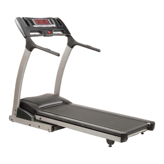
Page 7: Description
DESCRIPTION LECTRICAL ONFIGURATION Note: Electrical servicing of this treadmill is limited to board level replacement. 1. SEARS 30427 0 TREADMILL COMPONENTS a) Safety key: Magnetic key that fits in the Console to activate all functions. b) Console: Interface that controls all functions of the treadmill. -
Page 8: B General Information
ENERAL NFORMATION 1. CONSOLE a) Contains touch controls and 7 segment LED windows Display 2. MAIN CONTROLLER a) Contains power supply and control circuits 3. TREADMILL MOTOR a) Variable speed reversing 0-90 volt DC motor. Has three wires, red, black and green. If there is DC voltage on the Red wire (M+) the treadmill motor will turn clockwise. -
Page 9: S E R V I C E M A N U A L S E A R
Figure 1 Operational Flowchart... -
Page 10: Operation
OPERATION INDOW ISPLAY 1. OFF MODE a) When user doesn’t insert the SAFETY KEY on the console, the treadmill enters the OFF Mode and all windows will appear blank. 2. READY MODE a) When the treadmill is ON and the SAFETY KEY is inserted on the console, the LED display’s all windows for 1 second, the dot matrix will show “Press user WEIGHT”... -
Page 11: B Function
UNCTION 1. SPEED a) Displays the current speed in Miles per hour. b) DISPLAY range is 0.0 to 99.9 mph. c) WORK range is 1.0 to 12.0 mph. d) Press “FAST” or ”SLOW” to adjust speed, each increment and decrement is 0.1 mph. 2. -
Page 12: Laps
In RUN Mode, press “STOP” button to save value of time. Enter “RUN Mode” again, the value will continue from count up or count down time. 4. LAPS a) Displays the total working lap quantity, LAPS and TIME value display are in the same window and pressing “ENTER”... -
Page 13: Auto-Folding
a) DISPLAY range is 0 to 999. b) WORK range is 60 to 220. c) In RUN Mode, if the treadmill doesn’t have a signal for 8 seconds then the value will become “P”. 8. AUTO-FOLDING Press and hold Auto-Folding Switch at back of Left Handrail and console will emit a buzzing sound which means the treadmill is ready to be folded. -
Page 14: C Function Utton Ain Ode
UNCTION UTTON 1. READY MODE a) SAFETY KEY: Inserting the safety key in position will power on the computer. When safety key is pulled away from its position, the computer will automatically shut down. b) PROGRAM button: Press “PROGRAM” button to select training in different program profiles, P1 is manual, P2~P6 is PRESET PROGRAM, H1~H2 is HEART RATE CONTROL, U1~U3 is USER. -
Page 15: Run Mode
SPEED RAPID button: Has five buttons 2, 4, 6, 8, 10mph. When pressing “SPEED RAPID” button, there will be 3 seconds final count down by a buzzer, then the treadmill starts running at the preset speed in MANUAL mode. k) INCLINE RAPID button: Has five buttons 1, 3, 5, 7, 9 position. -
Page 16: D Calibration Procedure
ALIBRATION ROCEDURE 1. CALIBRATION NOTE: Do not stand on the treadmill while calibrating. a) Turn on power (ON / OFF SWITCH) b) Press “START” and “FAST” button at the same time. c) Inserts the SAFETY KEY on monitor, all windows will appear blank. -
Page 17: Verifying Calibration
m) After calibrating itself the treadmill will enter “READY MODE”. 2. VERIFYING CALIBRATION a) Turn on power. b) Press “START” and “SLOW” button at the same time. c) Insert the SAFETY KEY on the monitor to enter the first step of the verifying mode. d) SPEED Window should display the incline value of 10, INCLINE Window should display the wheel size to be 2.30. -
Page 18: Troubleshooting
TROUBLESHOOTING WARNING: ALWAYS UNPLUG THE TREADMILL FROM THE ELECTRICAL OUTLET BEFORE SERVICING THE UNIT. 1. GENERAL a) Do a visual check of all wiring and connections looking for cut wires or loose connections. b) Make sure any wiring is safely positioned and/or secured away from moving parts. -
Page 19: Troubleshooting
2. TROUBLESHOOTING Condition Reason Solve ON/OFF switch isn’t Power cord isn’t plugged into the outlet in the right Plug the power cord into the outlet. bright. position. Power cord isn’t plugged into the unit. Plug the power cord into the unit. The voltage of outlet is too low. - Page 20 Computer cable (12PIN) is defective. Replace computer cable. Fuse on the controller is defective. Replace controller. Controller is defective. Replace controller. Reed switch is defective. Replace reed switch. Monitor is defective. Replace console. Treadmill displays and Reed switch is defective Replace reed switch.
- Page 21 Monitor displays “LS” 1. Motor wires (red, black) are not plugged into the Turn off power and reset the treadmill. error message after 8 controller. seconds of pressing the 2. Computer cables are not connected properly. Reconnect the cables. “START” button and 3.
- Page 22 INCLINE window VR value of incline motor is incorrect. Calibrate the monitor. display’s “E2”. See calibration page. INCLINE window VR value of incline motor is incorrect. Turn off power and reset the treadmill. display’s “E2” while using the treadmill. INCLINE window Walking Deck position is incorrect.
- Page 23 FAST/SLOW button of The upper speed cable is not connected properly in Reconnect the cable into the console. SPEED ADJUSTMENT the console. SWITCH is not working. The speed adjustment switch with cable is not Reconnect the cable to the adjustment properly connected to the upper speed cable.
- Page 24 No pulse displayed on Chest strap not properly positioned Re-position the chest strap according to monitor while using the owner’s manual. chest strap and receiver Distance between transmitter and receiver are not Ensure that the distance between the within 100mm range. transmitter and receiver is within the range specified.
- Page 25 Treadmill will fold Relay on the controller is defective. Replace controller and calibrate it. automatically without See calibration page. pressing the switch. Tread belt does not run in Tread belt tension not even across tread belt. See treadbelt adjustment the center. (see Appendix A) Tread belt hesitates while Insufficient lubricant on tread belt.
- Page 26 indicator signal Function Condition for LED to be on Reason Solve Motor speed Light is and/or dark while running the Does not have input. Replace controller. treadmill. POWER Controller power The DC voltage is normal, the light Voltage is not correct. Check the voltage (110-120V).
-
Page 27: Diagrams And Schematics
DIAGRAMS AND SCHEMATICS Figure 2 Console Layout Figure 3 Mechanical Layout... -
Page 28: Figure 4 Main Controller Information & Voltages
Figure 4 Main Controller information & voltages Figure 5 Function JK1 connector on Main Controller... -
Page 29: Table O F C O N T E N T S
console 12PIN computer cable(upper 800mm) plug 12P12C male 12P12C female connector breaker socket A.C. switch 10cm black cable 18cm black cable Incline motor 15cm white cable 18cm white cable 3PIN VR wire black cable white cable red cable JK3(Inc line-VR) controller ALT-6320 DOWN... -
Page 30: Figure 7 Schematic Diagram
Figure 7 Schematic Diagram... -
Page 31: Treadbelt Adjustment
APPENDIX A 1. TREADBELT ADJUSTMENT The treadbelt has been factory pre-adjusted, however if during the operation: 1/4 T U R N Figure 8 If Treadbelt slips The treadbelt is too loose: Tighten both rear roller adjusting bolts 1/4 turn clockwise using Allen wrench 1/4 TURN Figure 9 If tread belt shifts too far to the Right a) Set the treadmill speed to 3.5 mph/5.6 km. -
Page 32: Figure 10 If Tread Belt Shifts Too Far To The Left
c) Wait 15 seconds: if no change; turn the left adjusting bolt a 1/4 turn counter-clockwise using Allen wrench e) Repeat steps b and c until belt is centered 1/4 TUR N Figure 10 If tread belt shifts too far to the Left a) Set the treadmill speed to 3.5 mph/5.6 km. -
Page 33: Treadmill Lubrication
APPENDIX B 1. TREADMILL LUBRICATION Your treadmill should require little maintenance other then periodically applying lubricant. Lubricating under the treadbelt will ensure superior performance and extend its life expectancy. HOW TO CHECK TREADBELT FOR PROPER LUBRICATION Lift one side of the treadbelt and feel the top surface of the treadboard If the surface is (slick) to the touch, then no further lubrication is required If the surface is dry to the touch, apply one packet of lubricant HOW TO APPLY LUBRICANT... -
Page 34: Reset Switch Resetting
APPENDIX C Tripped Normal Figure 11 Resetting Reset switch 1. RESET SWITCH RESETTING a) If the red button of reset switch is tripped, it will protrude out from the face of the switch. b) Press in the red button of the switch. c) If the red button of reset switch is not tripped, that means normal. -
Page 35: Fuse Replacement
APPENDIX D Figure 12 Fuse replacement 1. FUSE REPLACEMENT If your treadmill loses power or will not start, check the fuse located on the motor controller. DANGER: Turn the power switch off and unplug the treadmill to reduce the risk of an electric shock Remove the motor cover Remove and replace the fuse on the motor controller Replace the motor cover... -
Page 36: Speed Sensor Adjustment
APPENDIX E 1. SPEED SENSOR ADJUSTMENT If the monitor does not display speed or distance the speed sensor and magnet may be misaligned. Follow these steps to check and realign. Remove the motor cover Check the spacing and alignment between the magnet on the right side of the front roller and the speed sensor on the frame.