
Related Manuals for Westinghouse IQ DATA PLUS II

Summary of Contents for Westinghouse IQ DATA PLUS II
- Page 1 TD 17271A DATA PLUS II™ LINE METERING AND PROTECTION SYSTEM USER'S MANUAL @Westinghouse 1989 Effective September, ELECTRICAL COMPONENTS DIVISION Courtesy of NationalSwitchgear.com...
-
Page 2: Genera L Specifications
If further information is desired by purchaser regarding his particular installation, operation or maintenance of his equipment, the local Westinghouse Electric Corporation representative should be contacted. -
Page 3: Table Of Contents
Overvoltage Detection Response ....32 6 . H IQ Data Plus II Insta l l a tion 6 . 1 .7 U ndervolta ge Detection Response ... . . 32 Record Sheet: SW3 . -
Page 4: Supply Module
QUICK LIST FOR IQ DATA PLUS II INSTALLAT ION It is suggested that you thoroughly fam i liarize yourself with 5. If installing an IQ DATA PLUS II equipped with a 3-phase the IQ DATA PLUS II User's Manual before attem pting instal... -
Page 5: Introduction
IQ Data Plus II m icroprocessor. A com plete listing of the monitored values is g iven in Table 3.A on pag e 1 3. -
Page 6: Features A Nd Options
A l ist of features and benefits is system and who is determining the s etpoint val ues for a given in Table 1 .A (page 6) . Since the IQ Data Plus II is a s pecific IQ Data Plus I I application. -
Page 7: Al A Rm/Trip Leos
• • Allows for widesprea d standa rdization of units regard All 15 va lues metered ava ila ble in each IQ Data Plus II less of specific metering a nd control a pplication req uirements •... -
Page 8: Hardware Description
T he pu rpose of this Section is to fam ili a riz e T he description here is divided into the following : the reader with the IQ Data Plus II ha rdwa re, its nomenclatu re, • Operator Pa nel ( Pa r. 2.1.1) a nd to list the specifications of the u nit. -
Page 9: Operator Panel
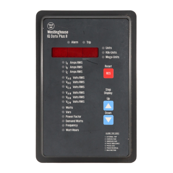
IQ DATA PLUS I I T D 17271A Figure Rear Access Area - Separate Source Power Module 2.18 Operator Panel T he Operator Pa nel, which is • Determine the cause of a tr ip or a larm condition by mea ns 2.1.1 norma lly a ccessible from the ou tside of the pa nel or door, of a single-digit code shown in the Display Window. -
Page 10: Dimensions
6. D I P switches, located o n the r ear r ight side of the chassis, T erminal Block at the bottom of the IQ Data Plus I I . tailor each IQ Data Plus II to a specific application . These D I P switches are set according to character istics such as: 2 . -
Page 11: Sync Pulse
• An overvoltage is detected when the ampli synchronizing the IQ Data Plus II with the demand window the tude of the AC line voltage exceeds 1 05, 1 1 0, 1 15, 120, utility billing is b a sed o n . The SYNC PULSE is activated by 125, 1 30, 1 35, or 140% of the no minal line voltage. - Page 12 TD 17271A IQ DATA PLUS I I Table 2.A GENERAL SPECIFICATIONS Device's Power Requirement < 1 > PT Burden (3-Phase Power Module) 10 VA PT Burden (Sep arate Source Power Module) 0.02 VA C.T. Burden 0.003 VA Frequency 5 0/60 Hz < 2 > Line Characteristics •...
- Page 13 TO 1 7271A IQ DATA PLUS I I Table 2.C PROTECTION FUNCTION SPECIFICATIONS < 1l Voltage Phase Loss Any p hase less than of nominal Current Phase Loss Smallest p hase less than 1 / 1 s of largest p hase Phase Unbalance<2l Line voltage ±...
-
Page 14: Pushbuttons
Disp lay Panel's face. Each time one of these p ushbuttons is Wi ndow. p ressed, the LED at the left of the newly selected (W ) WESTINGHOUSE IQ DATA PLUS I I • • ALARM... -
Page 15: Metered Va Lues
10 DATA PLUS I I TD 17271A Table 3.A METERED VAWES Display Selection Description Format XXXXXX lA Amps RMS Amps xxx.xxx 16 Amps RMS K Amps lc Amps RMS XXXXXX V A.e Volts RMS Phases A-to-8 xxx.xxx XXXXXX V e-c Volts RMS Phases 8-to-C xxx.xxx XXXXXX... -
Page 16: Blinking Leos
TD 17271 A IQ DATA P LUS I I Monitoring Inductive Loads - Typically when 3.2.1.2 monitoring induction motor loads the power flow is in Quad rant 4. The watts are positive and the power factor is lagging. VA RS QUADRANT 2 QUADRANT 1 WATTS NEGATIVE... -
Page 17: Display Window
T D 17271A IQ DATA PLUS II Alarm/Trip LEOs. The Alarm and Trip LEOs, when lit, • 3.2.3 Phase loss indicate that an alarm or trip condition ex ists, respectively. • Phase reversal At the same time a blinking digit, from 1 to 7 , appears in the •... -
Page 18: Installation And Startup
Do not high-pot or m egger this device. will remove excessive plastic from the holes, resulting in less threaded m aterial to secure the IQ Data Plus II to its mount 4.1 Panel Preparation - This Paragraph describes the panel ing panel. -
Page 19: Power Module
3 .60 Figure 4.2A Removable Power Module Place the IQ Data Plus II through the cutout in the panel. Be location desired. (See clearance dimensions i n Figure sure the Operator Panel faces outward. Use 0.5 in. (1 .2 e m) 4.2A or... -
Page 20: Remova Ble Separate Source Power
TD 17271 A IQ DATA PLUS I I Figure 4.28 Removable Separate Source Power Supply Module Shaded area designates information that replaces or supplements applications using the 1 20/240 VAC Separate Source Power Supply Module. -
Page 21: Wm Ng
These ranges are indicated on the Power Modul e, as shown in 6. T he protective fu nctions of the IQ Data Plus II directly Figu re 4.3. Consult the wiring plan drawings made up by the control the Trip or Alarm Relays, as described in Para... -
Page 22: Wiring Diagra
WIRE (UP TO VOLTS) D I R ECT VOL TAGE CONN ECTION & EXTERNAL C U RRENT TRANSFO R M E R S L I N E 1 CT LOAD IQ Data Plus II SYNC ALARM TRI P PULS E PULS E... - Page 23 IQ DATA PLUS I I TD 17271A PHASE WIRE (UP TO VOLTS) 2 CT's WIT H IQ DAT A PLUS II D I R ECT VOLTAGE CONN ECTION & EXTERNAL C U R R E NT TRANSFO R M E R S 1 CT L I N E LOAD...
- Page 24 TD 17271A IQ DATA P LUS I I PHASE WIRE (UP TO VOLTS) D I R ECT VOLTAGE CONNECTION & EXTERNAL C U R R E NT TRANSFO R M E R S 10 Data Plu s II SYNC PULS E TRI P ALARM PULS E �;�...
- Page 25 T D 17271A IQ DAT A PLUS I I PHASE WIRE (UP TO VOLTS) D I R ECT VOLTAGE CONN ECTION & EXTE RNAL C U RRENT TRANSFO R M E R S L I N E LOAD 1 20/240 VAC CONTROL POWER •...
- Page 26 Figure 4.41 Wiring Diagram PHASE WIRE (ABOVE VOLTS) 2 CT'S WITH IQ DATA PLUS II EXTERNAL POTENTIAL TRANSFOR M E RS & C U R RENT TRANSFO R M E R S L I N E LOAD FUSE O P E N D E LTA...
- Page 27 T O 17271A IQ DATA PLUS I I PHASE WIRE (UP TO VOLTS) D I R ECT VO LTAGE CONN ECTION & EXTERNAL C U R R ENT TRANSFORM E R S L I N E 1 CT LOAD 120/240 VAC CONTROL POWER SYNC TRI P ALARM...
-
Page 28: I Nitia L Sta Rtup
Courtesy of NationalSwitchgear.com... -
Page 29: Initial Power Application
TD 17271A IQ DATA PLUS I I Remove the 3 line fuses contained in the Power Module of the IQ Data Plus II. Figure 4.6 DIP Switch (side view) Turn on AC power and verify that the line-to-line voltages (A... -
Page 30: Theory Of Operati On
• Updating the Operator Panel o n a regular basis. When of how the IQ Data Plus II functions internally. Its purpose a component of the Panel - such as the Step Display is to give the user only an overview theory of operation. -
Page 31: Application Considerations
2 and 3 - be read thoroughly before proceeding. should then be made available to the installation team and to maintenance personnel. Paragraph 4.3 describes how to physically set the switches. Table 6.A IQ DATA PLUS II INSTALLATION RECORD SHEET: SW1 Setting Description Slide ON/OFF... -
Page 32: Line Frequency
100:5 overvoltage, undervoltage or phase unbalance condition is 150:5 first detected, the IQ Data Plus II can actuate its Alarm and 200:5 Trip Relays immediately; or the trip condition can be selected to continuously persist for several seconds before it actuates 250:5 the Alarm and Trip Relays. -
Page 33: Overvoltage Detection Response
6.1 .6 Overvoltage Detection Response Should an Should an over voltage condition be detected, the IQ Data Plus II can control undervoltage condition be detected, the IQ Data Plus II can the internal Trip and Alarm Relays in 4 ways: control the internal Trip and Alarm Relays in 4 ways: •... -
Page 34: Detection Response
Should either a phase loss or phase reversal condition be de the Alarm/Trip Relays are actuated as described in Paragraph tected, the IQ Data Plus II can control the internal Trip and 6.1 .23. Alarm Relays in 4 ways: 6.1 .9 Phase Unbalance Detection Response -... -
Page 35: Potential Transformers' Ratio
The secondary of the PT's must be 1 1 0 or 1 20 VAC, measured line-to-line. Place the Voltage Selector Jumper to 1 20 volts, as described in Paragraph 4.1 .4. The IQ Data Plus II is self-powered through the voltage 20:1 circuit connections. Therefore, when selecting external... -
Page 36: Peak Demand Window And Sync Pulse
(red) pushbutton on the front of the following list are also disabled. (Since they are disabled, the IQ Data Plus II while the demand LED is illuminated, or switches listed here may be left in any position.) In the ON remotely over the INCOM network. -
Page 37: Display Volts
For example, if are set to ON the wiring configuration for the system . ON-ON-ON, the IQ Data Plus II will close its Form C contact and send a short pulse every 100 watthours. SW4, Nos. 2 and 3 Switch specify these factors. -
Page 38: Line Overvolta Ge Detection Level
6.1.18 - The standard power factor calculation for the IQ Data Plus II is Wf\(W 2 + Q 2 for sinusoidal loads. If the user has a load waveform that is nonsinusoidal (e.g. chopped) or a load that is extremely light,... -
Page 39: Phase Unba La Nce Detection Level
ON position, Alarm Relays may be actuated. the IQ Data Plus II must also be set to determine how long the condition must exist before it actuates the Alarm and Trip SW6, Nos. 1 , 2 and 3... -
Page 40: Main Tenance
- This Section describes maintenance proce Installation and Startup, should be read thoroughly to familiar dures for the IQ Data Plus II. The information contained here is divided as follows: ize the maintenance person with the IQ Data Plus II. -
Page 41: Troubleshooting
Always disconnect and, if necessary, lock out the AC power completed , and source before touching the components on the rear of the IQ Data Plus II. Failure to do so can result in serious or • The l A AMPS RMS LED and Display Window do not dis... -
Page 42: Operational Troubleshooting
TD 17271 A IQ DATA PLUS I I Table 7.8 OPERATIONAL TROUBLESHOOTING Symptom Probable Cause(s) Solution All Operator Panel indicators are off. AC line being monitored is below 85 Locate the cause of the deficiency in VAC. (5) the AC line monitored. Separate Source AC line voltage is Locate the cause of the deficiency in deficient. -
Page 43: Operational
Courtesy of NationalSwitchgear.com... - Page 44 TD 17271A IQ DAT A PLUS I I NOTES Courtesy of NationalSwitchgear.com...
- Page 45 IQ DAT A PLUS I I T D 17271 A NO T ES Courtesy of NationalSwitchgear.com...
- Page 46 0> � As part of a constant effort to serve your needs, Westinghouse is interested in &ny information you can supply about your application or use of the 10-1000110 DATA PLUS II. If you would like to share this information, please check the box below.
- Page 47 9Nil3>11:fYW S.lOOOOI:fd NOil Y:>INOWWO:> = NllY o��s � Yd '41imq s J�td Jatua:> AeM)i J Bd s uoneJ odJo� 0 1 J 1� a 13 asno4 6u nsaM 33SS3tlOO'v' AS Ol'v'd 38 ll i M 38\fl.SOd SSe i ::J )SJI.::I l iVIAI Al d 3 tl S S3 N I S n 8 S3.1 V .lS 03.11 N n 3 H.l N l...