
Related Manuals for AVE Video Serial Synchronous ATM Interface VSSI-PRO

Summary of Contents for AVE Video Serial Synchronous ATM Interface VSSI-PRO
- Page 1 VSSI-PR VSSI-PR O O O O O VSSI-PR VSSI-PR VSSI-PR VIDEO SERIAL SYNCHRONOUS ATM INTERFACE Operation Manual APRIL 2006 Version 13...
- Page 2 2000 West Governors Circle Suite E, Houston, Texas 77092 Tel: 1-281-443-2300 Fax: 1-281-443-8915 Email: sales@aveusa.com http://www.americanvideoequipment.com AVE Thailand Co., Ltd. 2000-2006 AVE (Thailand) Co., Ltd. 217/4 Crystal Garden, Soi 4 (Nanatai) Sukhumvit Rd., Klongtoey, Klongtoey Bangkok 10110 Thailand Tel: 662-656-8231 Fax: 662-656-9554 Email: ave@avethailand.com...
-
Page 3: Table Of Contents
Features...6 Specifications...7 Connecting the VSSI-Pro...9 Introduction...9 Connecting the VSSI-Pro...9 ATM to VSSI-Pro Installation...10 VSSI-Pro Video Connection...10 VSSI-Pro Connections...10 External Alarm Output...12 Serial Input...12 Programming the VSSI-Pro...13 A Few Words About Programming...13 User Front Panel Controls...13 Programming - Getting Started...14 Programming Menus...15 Main-Menu for Programming...15 ATM Select...15 TCPIP 232 Adapter...16... - Page 4 CONTENTS Alarm Outputs (Continued) Flag Type...38 Flag Duration...38 Triggered Text...39 Test/Demo Mode...40 Port 1 Test...40 Port A Test...42 Port B Test...43 ATM Demo...44 Version Identification...45 Download/Upload Setup...45 Help...48 APPENDICES APPENDIX A : Data Dump Connections...49 APPENDIX B : Problem Solving Guide...50 APPENDIX C : Master Reset the VSSI-Pro...51 APPENDIX D : Frequently Asked Questions...52 APPENDIX E : RS-485 Networker...53...
- Page 5 CONTENTS FIGURES (Continued) Figure 17 : The VSSI-Pro Connections to TCPIP 232 Adapter...17 Figure 18 : TCPIP Interface Sub-Menu...18 Figure 19 : TCPIP Format I Sub-Menu...18 Figure 20 : TCPIP Interface Sub-Menu...18 Figure 21 : TCPIP Debuging Sub-Menu...18 Figure 22 : Custom Sub-Menu...18 Figure 23 : Screen Setup Sub-Menu...19 Figure 24 : Clock Sub-Menu...20 Figure 25 : On-Screen Titler Sub-Menu...21...
-
Page 6: Features
...Number of Display Lines Programmable ...Supports DVR Command Set for Auto Search Capability ...Supports the AVE Networker & Hydra for connection to many 3rd party DVR manufacturers ...Programmable on-screen time/date display. The on-board real-time clock can run in stand-alone mode or locked to ATM time/date mode ...Auto / Manual Network Configuring... -
Page 7: Specifications
SPECIFICATIONS Video In (BNC) Video Out (BNC) Video S / N Video B / W Power (DC Coax 2.1mmx5.5mm) Battery Backup NiMH Serial Ports (DB-9) Female Serial Port 1 Baud Rate Word Length Parity Stop Bits Serial Port A or B Baud Rate Word Length Parity... - Page 8 SPECIFICATIONS Watchdog Timer Hardware and Software Temperature Rating Humidity VSSI-Pro Beige Metal Enclosure Maximum Size with Connectors Packed in White Box with Manual VSSI-Pro VIDEO SERIAL ATM INTERFACE 0 – 50 degrees Celsius 32 – 122 degrees Fahrenheit Non-Condensing 85% RH 0.70 Kg or 1.55 lbs 130L x 127W x 38H (mm) 5.12L x 5W x 1.5H (in)
-
Page 9: Connecting The Vssi-Pro
The most typical VSSI-Pro connection is between the ATM’s modem and the ATM’s SDLC, BISYNC, or ASSYNC network. This is done using the AVE Triport ATM 2CH cable. The triport has male and female DB-25 connectors back-to- back which connect to the ATM modem and the ATM network. From the side of the back-to-back DB-25 connectors extends a cable with a DB-9 male connector which plugs into the VSSI-Pro rear port labeled “RS-232”. -
Page 10: Atm To Vssi-Pro Installation
CONNECTING THE VSSI-PRO ATM TO VSSI-PRO INSTALLATION Locate the connector on the ATM’s modem and loosen the 2 retaining screws, then quickly plug in the appropriate DB- 25 connector of the triport into the modem. Next plug the modem cable into the other DB-25 connector of the triport, and plug the DB-9 connector into the VSSI-Pro. -
Page 11: Table 1 : Pin-Out Of The Db-9 Connector On The Vssi-Pro
Cable and Connection: Pin-out of the DB-9 connector on the VSSI-Pro. PIN NUMBER Table 1: Pin-Out of the DB-9 Connector on the VSSI-Pro This interface uses the Triport ATM 2CH cable to tap the communication between the ATM machine and modem. (See pin-out below.) DB-9 (MALE) VSSI-Pro WITH DATA-OUT OPTION... -
Page 12: External Alarm Output
CONNECTING THE VSSI-PRO To interface with a camera port, the following cable should be used. Cable between ATM camera interface and VSSI-Pro: CAMERA INTERFACE DB-25 (MALE) WITH DATA-OUT OPTION Table 3: Pin-Out of the ATM Camera Interface DB-9 Male Connector DB-25 Male EXTERNAL ALARM OUTPUT You will be able to tie your exceptions to one open collector hard alarm output. -
Page 13: Programming The Vssi-Pro
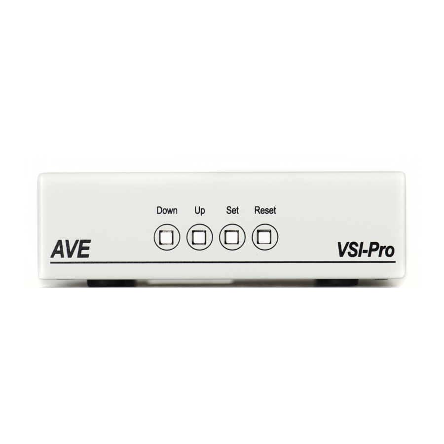
PROGRAMMING THE VSSI-PRO A FEW WORDS ABOUT PROGRAMMING The VSSI-Pro is programmed by pressing and releasing specific combinations of the four front panel push-buttons. Via these four simple buttons, all of the powerful programming features of the VSSI-Pro are available to you. A video source and a monitor must be connected in order for you to see the programming menus. -
Page 14: Programming - Getting Started
PROGRAMMING THE VSSI-PRO Changing the Horizontal Position Down Figure 5: Four Front Pannel Push-Buttons of VSSI-Pro (Up) 1. Press and hold the “Up” button. 2. Press and release the “Reset” button. 3. Release the “Up” button. 4. Press “Down” or “Up” to move the text block. 5. -
Page 15: Programming Menus
PROGRAMMING MENUS To access the main-menu of the VSSI-Pro, simultaneously hold down the “Down” and “Up” buttons, press and release the “Reset” button, and then release the “Down” and “Up” buttons. This will take you to the main programming menu. To navigate through this menu, press the “Down”... -
Page 16: Tcpip 232 Adapter
PROGRAMMING THE VSSI-PRO This sub-menu is selected when connecting to SNA or X.25 modem taps. The most common is FORMAT I but if the data does not display in a pleasing format try FORMAT II-IV. The CAT ELF is for the Citibank ATM network only. SDLC FORMAT I SDLC FORMAT II SDLC FORMAT III... -
Page 17: Figure 16 : Tcpip 232 Adapter Connections
TCPIP 232 Adapter Connections 1. Remove the ATM LAN Cable which is connected direct to the ATM and then immediately plug it in to the TCPIP 232 Adapter. Loop the LAN cable which came with TCPIP 232 Adapter via the RJ-45 Port on the TCPIP 232 Adapter rear panel to the ATM. -
Page 18: Figure 18 : Tcpip Interface Sub-Menu
PROGRAMMING THE VSSI-PRO The TCPIP INTERFACE sub-menu: 1. Press the “Up” or “Down” button to move the cursor to “TCPIP FORMAT I” and press “Set” to enter and change the IP address to the same as ATM’s IP address. EXAMPLE: If the ATM’s IP address is 192.168.0.141, set the address on the TCPIP 232 Adapter using this menu. -
Page 19: Custom
CUSTOM The custom settings are for special programming done for various customers to format the display or to interface to a proprietary network exclusive to that customer. The following sub-menu will appear: SCREEN SETUP On the main-menu, press the “Up” or “Down” button to move the cursor to following sub-menu will appear: TEXT GRAYSCALE To change the gray scale of the on-screen text, press the “Up”... -
Page 20: Clock
PROGRAMMING THE VSSI-PRO CLOCK To program the clock's functions, use the “Up” and “Down” buttons to move the cursor to “CLOCK” and press “Set”. The following sub-menu will appear: NOTE Enabling the clock limits the number of display lines to 10 maximum. T/D DISPLAY turns the time/date display on or off. -
Page 21: More On Time/Date Locking
MORE ON TIME/DATE LOCKING If the time/date locking is turned on, the VSSI-Pro will monitor the incoming data string. If it finds a valid time and date in one or two consecutive lines, it will set the clock to whatever time/date it finds. A valid time has the following formats: where hh is a number between 0 and 24 or 0 and 12 if either AM of PM is present. -
Page 22: Text Display
PROGRAMMING THE VSSI-PRO When the desired time/date is displayed, press the “Up” and “Down” buttons simultaneously to enter the title into memory and return to the menu. The white boxes will disappear and your title will be displayed as it will appear on-screen. NOTE Remember, enabling the titler will limit text insertions to 10 lines maximum, and with the clock on then 9 maximum. - Page 23 DISPLAY LINES Choices: 1 through 11 You have the choice of how many lines of text to display on-screen for register transactions. The choices are 1 through 11. Press the “Up” or “Down” button to move the cursor to “DISPLAY LINES” and press “Set”. The cursor will begin flashing.
-
Page 24: Display
PROGRAMMING THE VSSI-PRO DISPLAY Choices: ON, OFF You have the choice to globally turn on or off the complete VSSI-Pro text insertion function. This means no data will be visible on the monitor if you select DISPLAY “OFF”. However, if you select the DISPLAY “OFF”, you can still command each exception independently to either display on-screen or not through its program setup sub-menu under EXCEPTION REPORTS. - Page 25 VSSI-Pro does not require it.The VSSI-Pro's handshaking signal is always present. Handshaking guarantees that the internal buffer is not over-run or that text is not lost. The AVE Networker or Vnetworker suports this protocol but most other AVE interfaces do no support this function. Press the “Up” or “Down” button to move the cursor to “HANDSHAK- ING”...
-
Page 26: Port A : B
PROGRAMMING THE VSSI-PRO PORT A : B Again, there is probably no need for you to access this menu as it should be used for testing purposes only. You should rely on the setting chosen in ATM SELECT, but we will provide a brief overview of this menu. Press the “Up” or “Down” button to move the cursor to “PORT A : B”... -
Page 27: Bisync
DATA BITS Choices : 7 or 8 Press the “Up” or “Down” button to move the cursor to “DATA BITS” and press “Set”. The cursor will start flashing. Press the “Up” or “Down” button to toggle between values and press “Set” when the desired value is displayed. In addition to each item in this sub-menu and in the sub-menus for BISYNC and SDLC will be the settings for these formats, one of which you chose in the ATM SELECT sub-menu. -
Page 28: Exception Report
PROGRAMMING THE VSSI-PRO NOTE Added to DATA ENCODE in this sub-menu is the choice of AUTO along with NRZ, NRZI, NRZID. Otherwise the settings available are the same as in the BISYNC or ASYNC menus. EXIT Press the “Up” or “Down” button to move the cursor to “EXIT” and press “Set” to return to the previous menu. EXCEPTION REPORT The Exception Report gives you the option to assign an on-screen flag, trigger an alarming device, or send data to another serial device on any questionable transaction that you have preprogrammed into the VSSI-Pro. -
Page 29: Printer Or Dvr Output
PRINTER or DVR OUTPUT There may be situations where you do not want tellers or other employees to know what triggers an exception. In this case, the VSSI-Pro provides a seperate output that will send data to a remotely located serial printer. If you turn the on- screen display off and the output on and you have a remote serial printer hooked up to the VSSI-Pro, then whenever an exception is reported it is sent out to the serial printer only. -
Page 30: Dvr Selection
PROGRAMMING THE VSSI-PRO Example: Define “WITHDRAWAL” as an exception string in Exception No. 2 with the DISPLAY “ON” and define RANGE “100.00- 1000.00” and define OPERATOR ”IN”. NOTE For any exception you must program DISPLAY “ON” for any exception data to be saved in the Exception History. -
Page 31: Figure 38 : Vssi-Pro With Dvr Connections
PROGRAMMING THE VSSI-PRO DEST ID and SRC ID Choices: 1 through 32 Press the “Up” or “Down” button to move the cursor to “DEST ID” or “SCR ID” and press “Set”. The cursor will start flashing. Press the “Up” or “Down” button to toggle between values and press “Set” when the desired value is dis- played. -
Page 32: Time Search
PROGRAMMING THE VSSI-PRO TIME SEARCH TIME SEARCH SETTING NOTE For any exception you must program Display “ON” for any exception data to be saved in the Exception History. USING TIME SEARCH FUNCTION Press the “Up” or “Down” button to move the cursor to appear: Press the “Up”... -
Page 33: Set Exception
OUTPUT EXCEPTIONS This selection allows you to have the buffered exceptions sent out for printing. This is a global setting for all exceptions, but you also need to turn on the output for each independent exception. CLEAR HISTORY This selection clears all the buffered exceptions and resets the TOTAL EXCEPTIONS counter. EXIT Returns you back to the EXCEPTION REPORT menu. -
Page 34: Exception String
PROGRAMMING THE VSSI-PRO DISPLAY Choices: ON, OFF This display item lets you control whether or not a particular exception is displayed on the video monitor or not. If you do not turn on the exceptions display here, you will not have the on-screen flag and consequently no record of the exception when it occurs. -
Page 35: Negative Exceptions
WILDCARD: The wildcard symbol “•”, a centered dot, excepts on any data in that position. Press the “Up” or “Down” button to move the cursor to “EXCEPTION STRING” and press “Set”. The first position of the 20 character exception will become active by flashing. Program in your exception string. NOTE Remember to enter your exception string based on the way the data prints to video, including spaces, and remember pressing “Set”... -
Page 36: Alarm Outputs
PROGRAMMING THE VSSI-PRO NAVIGATING THE RANGE AND THE EXCEPTION STRING Before you define your range, we need to explain how to navigate through the range and exception string using the front panel switches. To program the range, press the “Up” or “Down” button to move the cursor to “RANGE” and press “Set”. The first “0”... -
Page 37: Alarm No
NOTE The VSSI-Pro provides one hard alarm output to trigger other devices such as VCR’s, DVR’s, QUADS, Enunciators, LED’s, or other alarming devices. The ALARM OUTPUTS menu controls not only the formatting of the external alarms, but also the formatting of the on- screen flags assigned to individual exceptions. -
Page 38: Normal State
PROGRAMMING THE VSSI-PRO Pin 1 on the DB-9 is Alarm 1 and Pin 5 is ground. To select the alarm trigger that you want to program, press the “Up” or “Down” button to move the cursor to “ALM TRG” and press “Set”. The cursor will start flashing. Press the “Up” or “Down” button to cycle through the values and press “Set”... -
Page 39: Triggered Text
TRIGGERED TEXT Triggered Text is a data string that associates with one of the 16 alarms. When the alarm is triggered by a source, the associated string is sent out and/or displayed if enabled respectively. Each Triggered Text can contain up to 40 printable ASCII data. -
Page 40: Test/Demo Mode
PROGRAMMING THE VSSI-PRO TEST/DEMO MODE The Test/Demo Mode provides you with several ways to test the VSSI-Pro and show its capabilities as an ATM interface. There is no actual programming in this menu that you need to do now or settings that you would change. You will probably only run the tests for troubleshooting purposes, and the demos would be helpful for demonstrating the VSSI-Pro to a customer without actually having to access an ATM. - Page 41 NOTE In any of these tests, you can pause the data scrolling by holding down either the “Up”or “Down” button. The VSSI-Pro is now waiting for data from the ATM. Enter a transaction. If the VSSI-Pro is receiving data, it will appear in three separate lines, scrolling from right to left across the bottom of the on-screen display.
-
Page 42: Port A Test
PROGRAMMING THE VSSI-PRO BAUD RATE SCAN There may be times when the baud rate cannot be detected on start-up. In the Baud Rate Scan test, you can scan for the baud rate of your interface. Press the “Up” or “Down” button to move the cursor to “BAUD RATE SCAN” and press “Set”. -
Page 43: Port B Test
TRANSMIT [ TX ] TEST Press the “Up” or “Down” button to move the cursor to “TRANSMIT [ TX ] TEST” and press “Set”. The following display will appear (example only): Press “Set” to return to the previous menu. EXIT Press the “Up”... -
Page 44: Atm Demo
PROGRAMMING THE VSSI-PRO CAPTURE TO MEMORY Press the “Up” or “Down” button to move the cursor to “CAPTURE TO MEMORY” and press “Set”. The following display will appear (example only): Press “Set” to return to the previous menu. DUMP TCP/IP Press the “Up”... -
Page 45: Version Identification
LOGO This demo displays the AVE logo cycling through several sizes.To access this demonstration, place the arrow in front of LOGO and press and release “Set”. The demo will start, but again, you will have to reenter the main menu if you want to continue viewing your programming options. -
Page 46: Figure 61 : Download/Upload Setup Using Vssi-Pro To Vssi-Pro
PROGRAMMING THE VSSI-PRO DOWNLOAD/UPLOAD SETUP USING VSSI-PRO TO VSSI-PRO To insure that the DOWNLOAD/UPLOAD process is accomplished, you need to access the programming menus for both VSSI-Pros, so each VSSI-Pro needs a video input and a monitor. The optimum way to perform the DOWNLOAD/ UPLOAD process would be to have a system set up with two separate cameras and monitors and the programmed VSSI-Pro with the download data cable attached. -
Page 47: Figure 62 : Download/Upload Setup Sub-Menu
NOTE The Download/Upload feature can only be used on VSSI-Pro's with the same software revision level. To proceed with the DOWNLOAD/UPLOAD SETUP, we will configure the UNPROGRAMMED VSSI-Pro first. From the main-menu, press “Up” or “Down” to move the cursor to “DOWNLOAD/UPLOAD SETUP” on the menu on the right side of the screen. -
Page 48: Help
DOWNLOAD/UPLOAD SETUP USING A PC You can use a Laptop PC and AVE’s IC or equivalent communications program to store data from a VSSI-Pro to a file. This file can then be uploaded to other VSSI-Pro units with the same software revision level. Use 4800 baud for the PC’s baud rate. -
Page 49: Appendix A : Data Dump Connections
DATA DUMP CONNECTIONS DATA DUMP CONNECTIONS To execute a data dump you will have to connect wires from the DB-9 connector of the VSSI-Pro to either Com 1 or Com 2 of a computer, using the following pin-out diagram: SDLC / BISYNC CAMERA PORT / JOURNAL / TCPIP CAMERA PERFORMING A DATA DUMP... -
Page 50: Appendix Bproblem Solving Guide
APPENDIX B PROBLEM SOLVING GUIDE This section contains a Problem Solving Guide and additional information regarding AVE's interfaces, cables, tips, and special applications. NOTE Before attempting to install your system, we highly encourage you to get your customer to demonstrate to you that their ATM is operating properly. -
Page 51: Appendix C : Master Reset The Vssi-Pro
MASTER RESET THE VSSI-Pro MASTER RESET THE VSSI-PRO Simultaneously press and hold down the “Down”, “Up” and “Set” buttons. While holding these three buttons down, press and release the “Reset” button and then release the other three. Our copyright notice will appear and then disappear and the message “SET UP”... -
Page 52: Appendix Dfrequently Asked Questions
If these don't seem to have an effect then try using a distribution amp like AVE's VDA-601 to properly adjust the video level. -
Page 53: Appendix E : Rs-485 Networker
RS-485 NETWORKER RS-485 NETWORKER The RS-485 Networker is designed to convert the RS-232 serial port output of the VSSI-Pro to be a poll/select network. This allows all the transaction data to be collected by one computer for up to 64 VSSI-Pros. APPLICATION Many users of the VSSI-Pro want to capture all the transaction data from several units to one device. -
Page 54: Appendix F : Pc Software With Atm Select
APPENDIX F PC SOFTWARE WITH ATM DATA The simple to install and use PC Software allows up to 64 VSSI-Pro ATM Interfaces to be configured on an RS-485 network and report all the transaction data back to a single monitoring computer. This Windows based software can be configured to display in a windowing horizontal format below or tiling in a vertical format. -
Page 55: Appendix G : Hard Alarm Output
HARD ALARM OUTPUT HARD ALARM OUTPUT The Alarm Output provides one open collector transistor alarm output to trigger alarming devices. Upon an Exception, a VSSI-Pro can be programmed to trigger a VCR to go to its fastest record time, have a Quad go full screen, home a switcher, trigger a preprogrammed PTZ, or provide visual or audible alarms. -
Page 56: Appendix H : Triport And Adapter Cable
APPENDIX H Triport and Adapter Cable Triports are typically used to passively tap data from a serial device. A Triport has three connectors, either 2DB-25's back to back or 2DB-9's and an additional DB-9 male which connects to the VSSI-Pro. The Triport ( and cable ) supplied with the VSSI-Pro is the ATM 2 Channel Triport. -
Page 57: Appendix I : Pin Assignment For The Time Search Function
PIN ASSIGNMENT FOR TIME SEARCH FUNCTION PIN ASSIGNMENT FOR TIME SEARCH FUNCTION VSSI-PRO TXDA 8 GND 5 Figure 1I: Pin Assignment for Time Search Function TCPIP 232 ADAPTER CONNECTION PIN-OUT Figure 2I: TCPIP 232 Adapter Connection Pin-Out SDLC / BISYNC / ASYNC ATM CONNECTION PIN-OUT Figure 3I: SDLC / BISYNC / ASYNC ATM Connection Pin-Out CAMERA CONTROLLER CONNECTION PIN-OUT Figure 4I: Camera Controller Connection Pin-Out... -
Page 58: Appendix Jlimited Warranty
APPENDIX J For 2 Years from the date of shipment, Seller warrants to Buyer that the Product is free from defects in material or workmanship under normal use and service. Equipment manufactured by other than Seller but furnished by Seller carries the same warranty to Buyer as Seller receives from the other manufacturer, notwithstanding any provision to the contrary. - Page 59 RETURNS AVE products are fully inspected and carefully packed to ensure you are delivered a quality product in good condition. If you are not fully satisfied with our product, returns of standard stocking items with no restocking fee can be made within thirty (30) days of invoice to Buyer.
-
Page 60: Appendix Knotes
APPENDIX K NOTES VSSI-Pro VIDEO SERIAL ATM INTERFACE... - Page 61 NOTES APPENDIX K VSSI-Pro VIDEO SERIAL ATM INTERFACE...
- Page 62 APPENDIX K NOTES VSSI-Pro VIDEO SERIAL ATM INTERFACE...
- Page 63 NOTES APPENDIX K VSSI-Pro VIDEO SERIAL ATM INTERFACE...
- Page 64 AVE Multiview UK Granyte House, Delamare Road Cheshunt, Hertfordshire EN8 9SP Tel: 440-870-770-9323 Fax: 440-870-770-9363 Email: enquiries@ave-uk.com http://www.multiview.net AVE (Thailand) Co., Ltd. 217/4 Crystal Garden Soi 4 (Nanatai) Sukhumvit Road, Klongtoey, Klongtoey Bangkok 10110 Thailand Tel: 662-656-8231 Fax: 662-656-9554 Email: ave@avethailand.com http://www.ave.co.th (Thailand)