
Related Manuals for Alto APM 120


Summary of Contents for Alto APM 120
- Page 2 CONTENT 1. INTRODUCTION……………………………………………………………………………..1 2. TECHNICAL SPECIFICATION……………………………………………………………..3 3. BLOCK DIAGRAM……………………………………………………………....5 4. SCHEMATIC DIAGRAM…………………………………………………………………….7 5. WIRING DIAGRAM………………………………………………………………………….11 6. PCB LAYOUT………………………………………………………………………………..13 7. TEST PROCEDURE………………………………………………………….....19 8. EXPLODED VIEW & MECHANICAL PARTS LIST……………………………………..29 9. BOM…………………………………………………………………………………………..33...
- Page 3 1. INTRODUCTION APM120 - 8 MONO Inputs with gold plated XLR and balanced TRS JACK. - GAIN and +48V Phantom power for mono/mic inputs. - 2 Stereo Inputs with balanced TRS Jacks. - Peak LED in each Channel. - 3-band EQ with sweepable MID on mono inputs. - 4-band EQ on stereo inputs - 24-bit internal DSP with 256 effects, 16 preset by 16 variations.
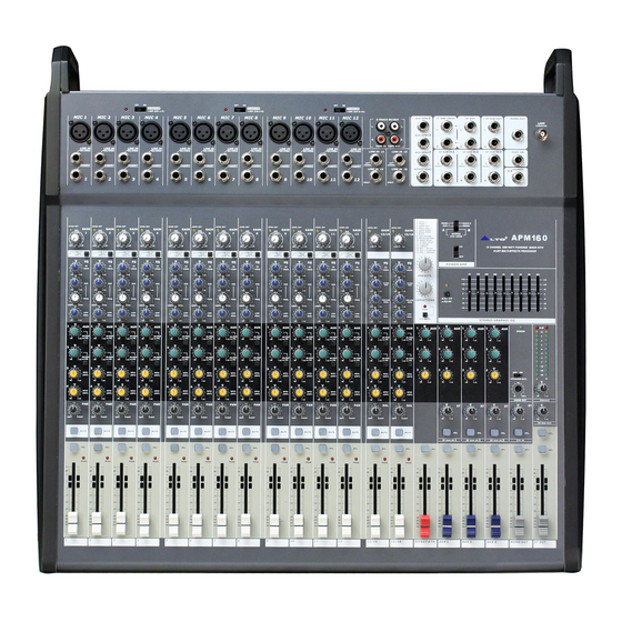
- Page 4 APM160 - 12 MONO Inputs with gold plated XLR and balanced TRS JACK. - GAIN and +48 Phantom power for mono/mic inputs. - 2 Stereo Inputs with balanced TRS Jacks. - Peak LED in each Channel. - 3-band EQ with sweepable MID on mono inputs. - 4-band EQ on stereo inputs.
- Page 5 Input Input Impedance Mic 2kohm Balanced Line 10kohm Balanced Input Gain Mic Continuously variable from 0dB to +45dB Input Gain Line-Mono Channel Continuously variable from -15dB to 30dB Input gain Line-Stereo Channel Continuously variable from -20dB to +20dB Maximum Input Level Mic +22dBu Line (Mono Channel) +22dBu Line (Stereo Channel) +22dBu...
- Page 6 Equalizer- Mono Channel Treble -shelving +15/-15dB @12kHz MID –peak/clip +15/-15dB – frequency range 100Hz~8kHz bandwidth 1 octave Bass –shelving +15/-15dB @80Hz Hi Pass Filter 18dB/oct @75Hz Equalizer –Stereo Channel Treble –shelving +15/-15dB @12kHz Hi Mid –shelving +15/-15dB @3kHz Lo Mid –shelving +15/-15dB @400Hz Bass -shelving +15/-15dB @80Hz...
-
Page 21: Test Procedure
7. TEST PROCEDURE Visual Check: 1. Check the APM120 (160) surface and be sure no frication of the unit. 2. Check all the screw and be sure that it installed in the right position; 3. Check all the knobs and be sure no frication of it; 4. - Page 22 After the test is OK, take the phantom jack out, the output is 0dB; 4). Press the LOW CUT key in the tested channel down, use AP to test the frequency specification, as for the fig1 After the test is OK, release the LOW CUT key; 5).
- Page 23 no output; b. Rotate the PAN knob to mid, the ST OUT L & R output is 0±2dB; c. Rotate the PAN knob to "RIGHT", the ST OUT R output is 2±2dB, but the ST OUT L has no output; After the test is OK, rotate the PAN knob to mid.
- Page 24 When it is in LINE IN R input, press the AUX1 key down and select the "PRE" output, the AUX1 output is -6±2dB; push the LEVEL in channel to "+10", the output has no variation; release the "PRE" key, the AUX1 output in 4±2dB. After the test is OK, push the channel slide potentiometer to "0", and make the AUX1 output is 0dB, then rotate the AUX1 knob to min "-∞".
- Page 25 output; After the test is OK, rotate the ST SUB knob to "0". 2). AUX SEND Output Test: a. Rotate the AUX knob in tested ST SUB channel to "-∞", the AUX has no output; b. Rotate the knob to mid "0", the output is 0±2dB (input from channel R is -6±2dB); c.
- Page 26 the PHONES L/R output is 0±2dB, and it has no PHONES output effect when push the slide potentiometer. After the test is OK, release the PFL key. 6). Press the AFL in ST OUT LEVEL slide potentiometer down, the Lens will light up, the PHONES L/R output is 0±2dB;...
- Page 27 EFFECCT RTN slide potentiometer and AUX1-AUX3 rotate potentiometer to "-∞". 9. Amplifier Output Test (RMS Test): Turn the POWER AMP switch to "ON", input from MIC1: -5dB sine waveform signal, rotate the GAIN to minimum, push the channel, ST OUT, AUX1 and MONO slide potentiometer to "+10": 1).
- Page 30 -100...
-
Page 33: Specification
No. Part No. Description Specification MA05851 ZC-board-RS-SR#2000 5249 APM120 ALTO-V1.0 HK07692 K-PC Board P-APM120 MONO-DIP MG00041 Screw-RS M3*6 HK07695 K-PC Board P-APM120 STEREO-DIP HK01409 K-PC Board P-313123-DIP(AMX-140FX) ME00015 color nut MG00234 copper pillar M3*5*0.5PH MF00037 MIC jack-RS-ACT-HC00125 attachment φ3*φ5*1t MG00036... - Page 34 No. Part No. Description Specification MA06242 ZC-board-RS-SR#2000 5249 APM160 ALTO-V1.2 HK07692 K-PC Board P-APM120 MONO-DIP MG00041 Screw-RS M3*6 NI03192 ZC-Lens-RS-ACT TYPHOON-V1.0 NI03140 knob-RS-C 5*5*9 dual TYPHOON-V1.0 HK07695 K-PC Board P-APM120 STEREO-DIP HK01409 K-PC Board P-313123-DIP(AMX-140FX) ME00015 color nut MG00243 copper pillar M3*5*0.5PH...
- Page 35 No. Part No. Description Specification Remark MA05851 panel-RS APM120 ALTO_V1.4 MA06198 panel-RS APM-120 AE00055 solvent solvent AE00235 paint-RS 5249 MA06197 panel-RS APM-120 1.2t*40*430*505_V1.2 MJ00063 iron board 1.2*2135*1220 24.54kg MB05006 chassis-RS APM120_V1.1 MB04970 chassis-RS APM-120 AE00055 solvent solvent 10 AE00235 paint-RS 5249 11 MB04969 chassis-RS APM-120 1.0t*488.28*430*99.5_V1.1...
- Page 36 φ4*φ7*1t 88 ME00016 color nut 4m/m 89 NI04569 rubber cushion-RS M6*φ23.5*20.5mm black 90 NA00235 PE bag 0.05t*650*550mm 91 NF00061 assurance card ALTO 92 HJ00006 dessicant 93 NE05004 label ALTO 94 NH00334 cone paper 0.040*1m 95 NE16529 lable-RS APM120_V1.0 96 NI00014 membrane 0.035*1M...
- Page 37 RLS4148 0.5A (LL-34) 121 SG00068 SMD integrated circuit 74HC14DT(SO14)/(PHI) 122 SG00410 SMD integrated circuit IC41LV16256-35KG(SOJ40)/(ICSI) 123 SG00166 SMD integrated circuit TY-2 ALTO(GMCODE:105022) 124 SG00147 SMD integrated circuit CHEF DSP(GMCODE:105022) 125 SG00037 SMD integrated circuit LD1117DT33C(TO252)/(ST) 126 HC00611 IC socket (SMD)
- Page 38 No. Part No. Description Specification Remark 169 CB00221 electrolytic capacitor 10uF/63V ±20% φ5*11mm C34,C35 170 CG00035 Y-type capacitor 4.7nF/400V C24,C42 171 CG00033 mteal oxide varistors B57237-S100-M RTH1 172 CB00254 electrolytic capacitor 47uF/100V φ10*12mm 5mm 173 HA01925 jump 10mm J5,J6,J9 174 HA02249 wire φ0.6 175 HA01930...
- Page 39 No. Part No. Description Specification Remark 225 MB04654 chassis DigiMod 3.0t*51*122*216(ME000155)_V1.1 226 MJ00057 AL plate-RS 3.0t*2000*1000mm 16.32kg 227 ME00220 iron pillar M4*8*0.7PH_V1.0 228 ME00221 iron pillar M3*4*0.8PH_V1.0 229 MK00115 spring-RS-C 1.0T*7.6*13*34.2(ML00004)_V 1.2 ML1,ML2,ML3,ML4,ML5,ML6,ML7,ML8 230 MC00801 top cover DigiMod 1.0t*48*116*136.8(ME000156)_V1.1 MEC2 231 MJ01323 hot gradual zinc 1.0t*2135*1220 20.45kg_V1.0...
- Page 40 No. Part No. Description Specification Remark 281 RH00034 thermistor-RS-CT 2.5Ω B57237S259M/(EPCOS) 282 HK07157 PC board P-DGM1000(PowerSoft)-SMD 283 SE00025 SMD diode 0.45A/85V BAV99 D18,D19,D20,D21,D26 R14,R15,R16,R17,R18,R19,R51,R52,R53,R54,R84,R85,R 284 RD00255 SMD precise resistor 1/4W 100KΩ ±1% 1206 88,R89 285 RD00245 SMD precise resistor 1/4W 1.00KΩ...
- Page 41 No. Part No. Description Specification Remark 335 SF00030 SMD transistor-RS-ACT BC817(SOT23)/(PHI) Q1,Q2/B 336 RD00298 SMD precise resistor 1/10W 47.0Ω ±1% 0603 R17,R19,R22,R34,R41,R87,R117,R119,R134,R141,R187 337 RD00201 SMD precise resistor 1/10W 1.50KΩ ±1% 0603 R6,R13,R65,R113,R165 338 RD00292 SMD precise resistor 1/10W 1.00MΩ ±1% 0603 R10,R60,R98,R99,R100,R110,R200,R209,R210 339 SG00001 SMD integrated circuit TL074CDT(SO14)/(ST)
- Page 42 No. Part No. Description Specification Remark 383 SG00496 SMD integrated circuit-RS LF412CDR(SO8)/(TI) U4/B,U104/B 384 CO00137 SMD inductance-RS 1.0mH ±5%(NL453232T-102J)/(TDK) L1,L101 385 SG00502 SMD integrated circuit-RS NE5532DR(SO8)/(TI) U1/B,U2/B,U101/B,U102/B 386 SG00504 SMD integrated circuit-RS-C ATmega8-16AU(TQFP32)/(ATMEL) U8/B 387 SG00509 SMD integrated circuit-RS HEF4069UBT(SO14)/(PHI) U5/B,U105/B 388 CI00278 SMD ceramic capacitor-RS 1206 0.0018uF/50V NPO ±5%...
- Page 43 No. Part No. Description Specification Remark R81,R82,R83,R84,R85,R86,R87,R88,R89,R141,R142,R14 431 RD00219 SMD precise resistor 1/10W 20.0KΩ ±1% 0603 3,R144 432 RD00105 SMD fixed resistor 1/10W 22KΩ ±5% 0603 R90,R91,R92,R93 C37,C38,C39,C40,C41,C42,C43,C44,C45,C46,C47,C48,C 433 CI00266 SMD ceramic capacitor-RS 0603 22PF/50V NPO ±5﹪ 49,C50,C51,C52,C53,C54,C55,C56,C109,C110,C111,C11 2,C113,C114,C115,C116 434 RD00106 SMD fixed resistor 1/10W 27KΩ...
- Page 44 No. Part No. Description Specification Remark 470 HA02249 wire φ0.6 J196,J201,J202,J203,J204,J205,J206,J207,J208,J209,J21 471 HA01930 jump 15mm 0,J211,J212,J213,J214,J215,J216,J217,J222,J223 472 HA02249 wire φ0.6 J138,J162,J176,J189,J190,J191,J192,J193,J194,J197,J19 473 HA01935 jump 12.5mm 8,J199,J200 474 HA02249 wire φ0.6 J149,J150,J151,J152,J153,J154,J155,J156,J157,J158,J15 9,J160,J161,J164,J166,J167,J168,J169,J170,J171,J172,J1 475 HA01925 jump 10mm 73,J174,J175,J177,J178,J179,J180,J181,J182,J183,J184,J 185,J186,J187,J188,J220,J221 476 HA02249 wire φ0.6 J82,J102,J103,J104,J105,J106,J107,J108,J109,J110,J111,...
- Page 45 No. Part No. Description Specification Remark 513 HC00473 connector-RS-ACT 2.45mm 180 2*8P B25-2*8BG1(B)H=5mm 514 HI00236 push-button switch-RS 2 6P PS-92 26A(SELF-LOCK) SW27,SW28,SW31,SW32,SW41,SW44,SW45,SW46 515 HI00238 push-button switch-RS 2 6P PS-92 26A(NON-LOCK) SW11 SW25,SW26,SW29,SW30,SW33,SW34,SW35,SW36,SW3 516 HI00237 push-button switch-RS 2 12P PS-13422 R(SELF-LOCK) 8,SW39,SW47,SW37 517 SA00053 L.E.D...
- Page 46 No. Part No. Description Specification Remark 565 NI01773 LED spacer support LEDS-13 566 HA04363 wire-RS 2P-2P 300mm UL1007 26AWG red/white 567 HA00829 wire-RS 304mm brown L3R3 568 HA00010 wire-RS 150mm black L5R5 569 AC00179 tin without lead-RS M705E Sn 3Ag-0.5Cu 570 HK07696 PC board P-APM120 STEREO-SMD...
- Page 47 No. Part No. Description Specification Remark R50,R60,R61,R62,R63,R64,R65,R66,R67,R68,R69,R70,R 71,R72,R73,R74,R75,R76,R77,R78,R79,R80,R81,R82,R83 595 RD00219 SMD precise resistor 1/10W 20.0KΩ ±1% 0603 ,R84,R85,R86,R141,R145,R239,R240,R241,R242,R246,R 247,R295,R353,R354,R384,R385,R452,R453 596 RD00119 SMD fixed resistor 1/10W 220KΩ ±5% 0603 R178,R179,R180,R181 597 RD00073 SMD fixed resistor 1/10W 220Ω ±5% 0603 R436,R437,R457,R458 598 RD00105 SMD fixed resistor 1/10W 22KΩ...
- Page 48 No. Part No. Description Specification Remark 633 AE00449 solder material without lead 9308/Sn Ag Cu 634 HK07697 PC board P-APM120 STEREO-AI 635 HB02186 PCB-RS APM120 STEREO_REV 1.10_VER060828 636 RA01112 fixed resistor 1/4W 100Ω R321 637 CB00120 electrolytic capacitor 100uF/16V φ5*11mm C80,C81,C82,C83 638 CC00060 mylar capacitor 0.1uF/100V 3%...
- Page 49 No. Part No. Description Specification Remark 682 MG00645 copper nut M3*16*0.5PH_V1.0 683 MI04055 fixed bracket-RS APM120 1.5t*25.5*34*487.5 right_V1.0 684 AE00055 solvent solvent 685 AE00235 paint-RS 5249 686 MI04054 fixed bracket-RS APM120 1.5t*25.5*34*487.5 right_V1.0 687 MJ00069 iron board 1.5*2135*1220 30.67kg 688 NA00210 PE bag 0.04t*200*430mm 689 MI04053...
- Page 50 No. Part No. Description Specification Remark 1 MA06242 panel-RS APM160 ALTO_V2.0 2 MA06205 panel-RS APM160 3 AE00055 solvent solvent 4 AE00235 paint-RS 5249 5 MA06204 panel-RS APM160 1.2t*40*535*505_V1.2 6 MJ00063 iron board 1.2*2135*1220 24.54kg 7 MB05007 chassis-RS APM160_V1.3 8 MB04976 chassis-RS APM160 9 AE00055 solvent solvent...
- Page 51 φ4*φ7*1t 88 ME00016 color nut 4m/m 89 NI04569 rubber cushion-RS M6*φ23.5*20.5mm black 90 NA00235 PE bag 0.05t*650*550mm 91 NF00061 assurance card ALTO 92 HJ00006 dessicant 93 NE05004 label ALTO 94 NH00334 cone paper 0.040*1m 95 NE16530 lable-RS APM160_V1.0 96 NI00014 membrane 0.035*1M...
- Page 52 RLS4148 0.5A (LL-34) 121 SG00068 SMD integrated circuit 74HC14DT(SO14)/(PHI) 122 SG00410 SMD integrated circuit IC41LV16256-35KG(SOJ40)/(ICSI) 123 SG00166 SMD integrated circuit TY-2 ALTO(GMCODE:105022) 124 SG00147 SMD integrated circuit CHEF DSP(GMCODE:105022) 125 SG00037 SMD integrated circuit LD1117DT33C(TO252)/(ST) 126 HC00611 IC socket (SMD)
- Page 53 No. Part No. Description Specification Remark 169 SA00316 bridge rectifier-RS 8A GBU-8K/(PANJIT) 170 NE16112 lable K-SERIES_V1.0 171 NI00020 membrane 0.07*1M 172 NH00015 bond paper 0.075*1M 173 MB04842 rear board DIGI MOD(ME000286)_V1.0 MEC1 174 ME00220 iron pillar M4*8*0.7PH_V1.0 175 ME00221 iron pillar M3*4*0.8PH_V1.0 176 MB04840 rear board DIGI MOD(ME000286)
- Page 54 No. Part No. Description Specification Remark 224 RD00399 10.0KΩ ±1% 1206 R11,R48,R47,R57 SMD precise resistor 1/4W 225 RD00255 SMD precise resistor 1/4W 100KΩ ±1% 1206 R14,R15,R16,R17,R18,R19,R51,R52,R53,R54,R84,R85,R88,R89 226 RD00608 33.0KΩ± 1% 1206 SMD precise resistor-RS 1/4W 227 RD00615 1.50Ω± 5% 0805 R22,R23,R45 SMD precise resistor-RS 1/8W 228 RD00607...
- Page 55 No. Part No. Description Specification Remark 278 SG00045 SMD integrated circuit BU4081BF(SOT73)/(PHI) U6/B 279 SG00509 SMD integrated circuit-RS HEF4069UBT(SO14)/(PHI) U5/B,U105/B 280 SG00001 SMD integrated circuit TL074CDT(SO14)/(ST) U3/B,U103/B 281 SE00077 SMD L.E.D-RS red KPTC-2012EC D19,D119 282 SE00078 SMD L.E.D-RS green KPTC-2012SGC D16,D17,D18 283 CO00137 SMD inductance-RS 1.0mH ±5%(NL453232T-102J)/(TDK)
- Page 56 No. Part No. Description Specification Remark 329 SD00079 integrated circuit L7915CV(TO220)/(ST) 330 SD00077 integrated circuit-RS L7815CV(TO220)/(ST/MOROCCO) 331 SD00066 integrated circuit L7812CV(TO220)/(ST) 332 SB00015 Pohtotriode 4N33.300 333 SA00223 zener diode 3.6W 36V KA431AZ(TO-92) 334 SA00221 bridge rectifier 2A/600V KBP206 335 SA00222 diode 2.2A/274V P6KE200A 336 SA00093 rectifier diode 1N4148 0.5A...
- Page 57 No. Part No. Description Specification Remark 385 RD00254 68.0KΩ ±1% 1206 SMD precise resistor 1/4W 386 RD00149 SMD fixed resistor 1/4W 220KΩ ±5% 1206 R4,R2,R3 387 RD00142 SMD fixed resistor 1/4W 10KΩ ±5% 1206 R10,R100 388 RD00146 SMD fixed resistor 1/4W 47KΩ...
- Page 58 No. Part No. Description Specification Remark C37,C38,C39,C40,C41,C42,C43,C44,C45,C46,C47,C48,C49,C50,C5 434 CI00266 22PF/50V NPO ±5﹪ 1,C52,C53,C54,C55,C56,C109,C110,C111,C112,C113,C114,C115,C SMD ceramic capacitor-RS 060 435 RD00106 SMD fixed resistor 1/10W 27KΩ ±5% 0603 R139,R140,R152,R153,R165,R166,R178,R179 436 RD00265 SMD fixed resistor 1/10W 27Ω ±5% 0603 R41,R42,R43,R44 437 RD00089 SMD fixed resistor 1/10W 2.7KΩ ±5% 0603 R226,R227,R228,R229,R230,R231,R232,R233 TR1,TR2,TR3,TR4,TR5,TR6,TR7,TR8,TR9,TR10,TR11,TR12,TR13, 438 SF00056...
- Page 59 No. Part No. Description Specification Remark J138,J162,J176,J189,J190,J191,J192,J193,J194,J197,J198,J199,J2 474 HA01935 jump 12.5mm 475 HA02249 wire φ0.6 J149,J150,J151,J152,J153,J154,J155,J156,J157,J158,J159,J160,J1 61,J164,J166,J167,J168,J169,J170,J171,J172,J173,J174,J175,J177, 476 HA01925 jump 10mm J178,J179,J180,J181,J182,J183,J184,J185,J186,J187,J188,J220,J2 477 HA02249 wire φ0.6 J82,J102,J103,J104,J105,J106,J107,J108,J109,J110,J111,J112,J11 3,J114,J115,J116,J117,J118,J119,J120,J121,J122,J123,J124,J125,J 478 HA02441 jump 7.5mm 126,J127,J128,J129,J130,J131,J132,J133,J134,J135,J136,J137,J13 9,J140,J141,J142,J144,J145,J146,J147,J148,J163,J165,J195 479 HA02249 wire φ0.6 480 HK07695 PC board P-APM120 STEREO-DIP 481 CC00041 mylar capacitor 0.12uF/100V 10%...
- Page 60 No. Part No. Description Specification Remark 519 HI00161 relay RY-5W-K,5V 520 HC00403 RCA jack SCP6873NS3232T2 4P 521 HI00195 rotary switch SDB161PVB15.5F-1-4-16-16PC EN1,EN2 522 HI00379 slide switch-RS 2stage 6P 6mm SKA-22-06B SW43 523 HI00381 slide switch-RS 3stage 8P 6mm SKA-23-06B SW42 524 HI00384 slide switch-RS 2stage 3P 4mm SBA-12CN-04RB...
- Page 61 No. Part No. Description Specification Remark 573 RD00059 SMD fixed resistor 1/10W 0.0Ω ±5% 0603 R466,R467 574 RD00224 SMD precise resistor 1/10W 100KΩ ±1% 0603 R464,R465 575 CI00059 SMD ceramic capacitor 0603 100PF/50V NPO ±5% C232,C233 C169,C170,C171,C172,C173,C174,C175,C176,C177,C178,C179,C1 80,C181,C182,C183,C184,C185,C186,C187,C188,C189,C190,C191, C192,C193,C194,C195,C196,C197,C198,C199,C200,C201,C202,C2 576 CI00075 0.1uF/50V Y5V +80,-20% SMD ceramic capacitor 0603 03,C204,C205,C206,C207,C208,C209,C210,C211,C212,C213,C214,...
- Page 62 No. Part No. Description Specification Remark 601 RD00063 SMD fixed resistor 1/10W 22Ω ±5% 0603 R497,R498 602 RD00074 SMD fixed resistor 1/10W 270Ω ±5% 0603 R489,R490 603 RD00106 SMD fixed resistor 1/10W 27KΩ ±5% 0603 R41,R42,R43,R44,R45,R46,R47,R48,R237,R238,R244,R245 604 RD00203 SMD precise resistor 1/10W 2.00KΩ...
- Page 63 No. Part No. Description Specification Remark 648 CB00268 electrolytic capacitor 330uF/16V φ8*11mm 5mm C279 649 CC00063 mylar capacitor-RS 0.0039uF/100V 10% C272,C273 650 CB00018 electrolytic capacitor 4.7uF/25V φ4*7mm C274,C275,C276 651 CC00078 mylar capacitor 0.047uF/100V 3% C234,C235,C236,C290,C163,C164,C165,C166 652 CB00246 electrolytic capacitor 0.47uF/50V ψ4*7mm C243,C244 C223,C224,C84,C85,C86,C87,C88,C89,C90,C91,C92,C93,C94,C95, C96,C97,C98,C99,C100,C101,C102,C103,C104,C105,C106,C107,C...