QSC Q-SYS Core 110f Hardware User's Manual
Hide thumbs
Also See for Q-SYS Core 110f:
- Technical notes (2 pages) ,
- Technical notes (2 pages) ,
- Hardware user's manual (13 pages)

Related Manuals for QSC Q-SYS Core 110f


Summary of Contents for QSC Q-SYS Core 110f
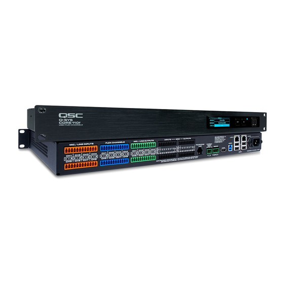
- Page 1 ™ Hardware User Guide Q-SYS Core 110f Q-SYS Cinema Core 110c TD-001541-01-B *TD-001541-01*...
- Page 2 EXPLANATION OF TERMS AND SYMBOLS The term “WARNING!” indicates instructions regarding personal safety. If the instructions are not followed the result may be bodily injury or death. The term “CAUTION!” indicates instructions regarding possible damage to physical equipment. If these instructions are not followed, it may result in damage to the equipment that may not be covered under the warranty.
- Page 3 To avoid a danger of subsequent damage to the apparatus, injuries to persons and/or the creation of additional safety hazards, all maintenance or repair work on the apparatus should be performed only by a QSC authorized service station or an authorized QSC International Distributor.
- Page 4 The QSC Q-SYS Core 110 Series is in compliance with European Directive 2011/65/EU – Restriction of Hazardous Substances (RoHS2). The QSC Q-SYS Core 110 Series is in compliance with “China RoHS” directives. The following chart is provided for product use in China and its territories: QSC Q-SYS Core 110 Series 部件名称...
- Page 5 Mic/Line In (orange) Flex Channels Mic/Line Out External Power (blue) (green) (green) RS232 Tx/Rx Core 110 QSC Warranty Rubber feet (green) Installation TD-000453 TD-001541 Installation The following steps are written in the recommended installation order. Rack-Mounting WAONORG!: Be sure that each side has a minimum of 2 cm clearance. Make sure that there is a fresh-air supply on the left side of the unit.
- Page 6 Rear Panel (left side) All audio inputs and outputs use one 3-position, 3.5mm Euro connector for each channel. GPIO uses one 10-position 3.5mm Euro connector for each row. All inputs and outputs are configured in Q-SYS Designer. — Figure 2 — Mic/Line Inputs –...
- Page 7 Connections Input / Output Connectors Balanced Unbalanced Figure 4 – Figure 7 3-Pin, color-coded, Euro Connectors • Mic/Line Inputs (8 orange) — Figure 4 — — Figure 5 — • Flex Channels (8 blue) • Mic/Line Outputs (8 green) WAONORG!: A single channel consists of three pins.
- Page 8 Communication and Power Connectors Make the following connections as required. Refer to Figure 5 Telephone Cable, RJ12,6-Conductor 2-pin Euro connector – for +12VDC 10A 3-pin Euro connector – for RS232 TX and USB Type B – for external devices, not supplied RJ45/Cat5E –...
- Page 9 System Status SYSTEM STATUS Refer to Figure 10 < rmware number> FIRMWARE: • Firmware – A three-section number identifying the major release, minor release, and maintenance release. For example, 5.0.06. <temperature in Celsius > TEMP: • Temp – The current chassis temperature of the Core. ◦...
- Page 10 Dimensions 18.9 in. 481 mm DESIGN STATUS DEVICE: <core name> <Design Name> DESIGN: <Status> STATUS: 18.9 in. 481 mm — Figure 14 — TD-001541-01-B...
- Page 11 Output Level Range (1 dB Steps) -39 dBu min to +21 dBu max Q-LAN Channels AEC Channels Q-SYS Core 110f Q-SYS Core 110c Core-to-Core Streaming Channels Default = 16, With optional MD-110 SSD and MTP-32 = 32 USB B (Audio)
- Page 12 Q-SYS Core 110 Series Specifications Specification Value Phantom Power +48VDC, 10mA per input max Sampling Rate 48 kHz Power Consumption 60 watts, typical. 120 watts max A/D – D/A Converters 24-bit BTU / Heat load 205 BTU/Hour Device Dimensions (HxWxD) 1.7"...
- Page 13 FAX: +1.714.754.6173 © 2015 – 2017 QSC, LLC. All rights reserved. QSC and the QSC logo are registered trademarks of QSC, LLC in the U.S. Patent and Trademark office and other countries. Q-SYS, Q-LAN and, Q-SYS Designer are trademarks of QSC, LLC. Patents may apply or be pending.