
Related Manuals for Oki BV1270SIP-OD


Summary of Contents for Oki BV1270SIP-OD
-
Page 1: Quick Start Guide
Oki. Network Solurlons Oki Electric Industry Co.,Ltd. For a Global Society Quick Start Guide BV1270SIP-OD E&M5 Interface Internal Number to IP Address Translation COMPATIBLE Firmware Ver: 1.5 Maintenance Console Software Ver: 3.4... - Page 2 BV1270SIP-OD OD Quick Start Guide Oki Electric Industry Co.,Ltd. This guide is designed to provide a quick and easy setup of the BV1270SIP-OD- E&M5 (OD Interface) Internet Voice Gateway. IP address, numbering plan and all other parameters are for sample purposes only. The guide configures the most basic required parameters.
- Page 3 BV1270SIP-OD OD Quick Start Guide Oki Electric Industry Co.,Ltd. IMPORTANT SAFETY INSTRUCTIONS Warning This warning symbol means danger. You are in a situation that could cause bodily injury. Before you work on any equipment, be aware of the hazards involved with electrical circuitry and be familiar with standard practices for preventing accidents.
-
Page 4: Installation Steps
BV1270SIP-OD OD Quick Start Guide Oki Electric Industry Co.,Ltd. Installation Steps Step 1 Hardware Installation 1. BV1270SIP-OD to KTS/PBX cables Step 2 Configuration 1. Unit Information Check firmware version. If firmware version is old version, you should do version up. - Page 5 BV1270SIP-OD OD Quick Start Guide Oki Electric Industry Co.,Ltd. STEP 1 – HARDWARE INSTALLATION Connecting Cables The following connections must be made to complete BV1270SIP-OD cabling. • Power Cable • Ground Cable • Interface Cables • RS-232C Cable • LAN Cable With the exception of the power cable, all cables must be prepared during the installation process.
- Page 6 Oki Electric Industry Co.,Ltd. Install Power Cable The power cable is supplied with the BV1270SIP-OD base unit. To install the power cable: Plug the DC connector on the AC adapter into the power connector located at the rear of the unit Plug the power cable into the AC adapter.
-
Page 7: Frame Ground
AWG cross-section 0.8mm • If a crimp connector other than the one supplied with the BV1270SIP-OD unit is to be obtained, use one that is 1.25-4 for use with a 4mm diameter screw and terminal part width of 8mm or less. - Page 8 Oki Electric Industry Co.,Ltd. Connect Interface Cables If pre -manufactured cables are not used cabling the BV1270SIP-OD interface may require the preparation of line cable connectors for the terminal side of the connection and LAN cable connectors for interconnection with LAN equipment such as routers and hubs.
- Page 9 BV1270SIP-OD OD Quick Start Guide Oki Electric Industry Co.,Ltd. Page 9 of 33...
- Page 10 BV1270SIP-OD OD Quick Start Guide Oki Electric Industry Co.,Ltd. Connect the other connectorized end of the cable to the PBX or similar remote equipment. E&M Tie Trunk Interface RJ45 KTS or PBX Terminal Block Figure 1-7: Connecting a unit to PBX E&M5 trunk board To complete the installation, all interface cables should be secured to the cable support bracket.
- Page 11 To attach cable restraints: Locate the snap band (wire tie) packaged with the BV1270SIP-OD base unit and the cable support bracket installed at the right side rear of the base unit. (On desktop units the bracket is attached to the unit chassis.
- Page 12 Oki Electric Industry Co.,Ltd. Connect Computer with RS-232C Cable To initialize a newly installed BV1270SIP-OD unit using the Common Maintenance Console Software Unit Information Setup Wizard, a computer or terminal must be connected directly to the unit using an RS-232C serial cable (straight-through) with DB9 Female to DB9 Female connectors.
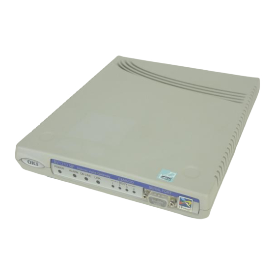
- Page 13 Note Serial poll connector PC computer Figure 1-10: BV1270SIP-OD serial port connection Notes: The connector of Serial Port is especially influenced by static electricity. Please do not remove a dust cap except the connection of maintenance console. Page 13 of 33...
-
Page 14: Connect The Network Cable
BV1270SIP-OD OD Quick Start Guide Oki Electric Industry Co.,Ltd. Connect the Network Cable A standard 10/100BaseT cable with an RJ45 connector is used to interconnect the BV1270SIP-OD unit with a network device. To install the Network connector cable: Insert the RJ45 connector into the BV1270SIP-OD LAN port located on the unit’s rear panel. - Page 15 Power-Up the BV1270SIP-OD and Verify Operation Once all connections have been made, the BV1270SIP-OD can be set to its power-ON condition. After the unit is powered-up, power should only be returned to the power-OFF state for installation or hardware maintenance activities.
- Page 16 Oki Electric Industry Co.,Ltd. Powering-Down the BV1270SIP-OD It is sometimes necessary to turn the BV1270SIP-OD unit OFF. This is the case for instance during some forms of maintenance or when relocating the unit. To turn the BV1270SIP-OD power OFF, pull up the power cable from the power supply outlet.
-
Page 17: Unit Information
172.17.68.1 • Connect the BV1270SIP-OD and PC with an RJ45 Ethernet straight cable via a hub. Alternatively you can connect a BV1270SIP-OD and PC directly by an RJ45 Cross Connect (rollover) cable. Connect the PC to BV1270SIP-OD using the Serial RS232C cable. - Page 18 BV1270SIP-OD OD Quick Start Guide Oki Electric Industry Co.,Ltd. Step 1 Execute IVG MCS on the computer connected to the BV1270SIP-OD OD unit IVG Maintenance Console Software startup Flash screen Step 2 Enter “mcs” - the default password Click “OK”...
- Page 19 Select Unit “BV1270GW” Select Version “C1.0” *Note Select Interface “OD” Note: Always select the FW version installed on your BV1270SIP-OD Firmware version of B BV1270SIP-OD should be the latest version. (Reference the BV1270SIP-OD Installation Guide for more information.) Enter Comments “San Jose Office”...
- Page 20 BV1270SIP-OD OD Quick Start Guide Oki Electric Industry Co.,Ltd. Step 8 The default Call control signal UDP port number value of 5006 is the SIP VoIP standard. Change it only if required. Click “Next Step 9 To select the default Maintenance Level Password “mainte”...
- Page 21 Serial Cable (DB9F-DB9F) along with the correct COM port settings The new IP address information will be uploaded to the BV1270SIP-OD using the RS232C serial interface. The BV1270SIP-OD OD unit will reboot and the new settings will be in effect...
-
Page 22: Configuration File
BV1270SIP-OD OD Quick Start Guide Oki Electric Industry Co.,Ltd. STEP 2 – Part 2 Configuration File Numbering Plan 1. San Jose to New york Using a local extension off the PBX. Access the PBX Trunk Ports connected to the San Jose BV1270SIP-OD unit. - Page 23 BV1270SIP-OD OD Quick Start Guide Oki Electric Industry Co.,Ltd. Step 12 Click “BV1270 OD” under the Unit name Right-click mouse and select “Edit configuration” Step 13 Select “Saved configuration file” Click “OK” Step 14 Click “OK” This selects the default CONFIG.DAT configuration file.
- Page 24 BV1270SIP-OD OD Quick Start Guide Oki Electric Industry Co.,Ltd. Step 15 Select “Numbering” tab Enter Office Code “99” (Unique Unit ID) (20 is the default) Important: “99” does not become part of the numbering plan. Step 16 Select “Trunk Data” tab Configuring Ports 1,2,3 &...
- Page 25 BV1270SIP-OD OD Quick Start Guide Oki Electric Industry Co.,Ltd. Step 17 Configuring E&M Hunt Group Code Click “Hunt Pattern" tab Enter Destination Number: “99” Enter Hunt Pattern no.: “1” (Default is 1) *note Click “Update” Important: E&M Hunt Group Code becomes part of the numbering plan.
- Page 26 BV1270SIP-OD OD Quick Start Guide Oki Electric Industry Co.,Ltd. IMPORTANT ADVANCED CONFIGURATION TABS The following example screens are for Advanced Configurations only and are included here only as a reference: Tone Tab Notify Email Tab Select from Tone libraries for US, JP, many EU countries, and Automatic email notification in case of line power failure, create Custom Tone Libraries.
- Page 27 BV1270SIP-OD OD Quick Start Guide Oki Electric Industry Co.,Ltd. Voice Mode Tab Fax related Tab Use this tab to set the Primary and Secondary CODEC’s to use. T.38 TCP Fax related settings. Also to adjust packet balances. Numbering2 Tab Numbering3 Tab Dialed Number conversion when Originating a call.
- Page 28 BV1270SIP-OD OD Quick Start Guide Oki Electric Industry Co.,Ltd. Call Control Tab Priority routing information Tab Used to specify routing ports for VoIP calls (QOS Routing Support) Set Type of service bytes (TOS) Differential Services (DiffServ) DS byte Recovery Delay Tab SNMP Tab Jitter Buffer Parame ter settings.
- Page 29 Before creating DNS.DAT, please understand the following flow-chart. The purpose of the DNS.DAT file is to do number to IP translation. It's function can be likened to an address book. It is necessary to have all the BV1270SIP-OD units within the network registered in the DNS.DAT file so that all the units can communicate with each other.
- Page 30 BV1270SIP-OD OD Quick Start Guide Oki Electric Industry Co.,Ltd. Step 19 Click “New Network” Step 20 Click “Tools” Click “DNS (Static transfer)” “Edit.” Step 21 The Configure DNS Settings Wizard. Click “Add” Step 22 Step 1 Enter the following:...
- Page 31 The above only saves the DNS.DAT file on the PC. Also if you are registering multiple BV1270SIP-OD units, please repeat Steps 21 & 22 for each unit. By registering all units in your deployment every unit can call all of the others including itself.
-
Page 32: File Transfer
BV1270SIP-OD OD Quick Start Guide Oki Electric Industry Co.,Ltd. STEP 3 File Transfer Step 24 Click “BV1270 OD” Right-click mouse and select “File Transfer” Step 25 File Selection Wizard Select: “Config file (CONFIG.DAT)” Select: “DNS file (DNS.DAT)” Check: “Reboot after file transmission”... - Page 33 BV1270SIP-OD OD Quick Start Guide Oki Electric Industry Co.,Ltd. Step 26 Click “Yes” File transfer in progress Step 27 File transfer results Click “Close” Congratulations! You have successfully completed the configuration of a BV1270SIP-OD OD unit. Page 33 of 33...