
Related Manuals for ABB M2302


Summary of Contents for ABB M2302
- Page 1 User manual M2302, Gateway Please select your language English Suomi Franç ais Norsk Polski Svenska Italiano Dansk Pусский Español 简体中文 Portuguê s Čeština Deutsch Slovenčina Nederlands...
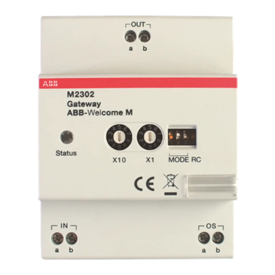
- Page 2 VER:1.2 │ │ 06.07.2016 ABB-Welcome Pos : 2 /Di nA4 - Anleitung en Online/Inhalt/KN X/D oorEntr y/83220- AP- xxx/Titelbl att - 83220-AP- xxx - ABB @ 19\mod_1323249806476_15.doc x @ 111084 @ @ 1 M2302 Gateway === Ende der Liste fü r T extmar ke Cover ===...
-
Page 3: Table Of Contents
Pos : 4 /Busch-J aeger (Neus truktur)/M odul-Str uktur/Online-Dokumentation/Inhal ts verz eic hnis (--> Fü r alle D okumente <--)/Inhalts verz eichnis @ 19\mod_1320649044386_15.doc x @ 109653 @ @ 1 Safety ......................3 Intended use ....................3 Environment ....................3 ABB devices ................. 3 Operation ....................... 5 Control elements ................5 Operating modes ................6 4.2.1... -
Page 4: Safety
ABB devices Pos : 13 /Busc h-J aeg er (Neustr uktur)/Modul- Struktur /Online-Dokumentati on/U mwel t (--> Fü r alle D okumente <--)/Hinweis e/Hi nweis - U mwelt - ABB El ektr ogeräte @ 19\mod_1323162745839_15.doc x @ 110867 @ @ 1 All packaging materials and devices from ABB bear the markings and test seals for proper disposal. - Page 5 ABB-Welcome ABB products meet the legal requirements, in particular the laws governing electronic and electrical devices and the REACH ordinance. (EU-Directive 2002/96/EG WEEE and 2002/95/EG RoHS) (EU-REACH ordinance and law for the implementation of the ordinance (EG) No.1907/2006) — 4 —...
-
Page 6: Operation
ABB-Welcome Pos : 18 /DinA4 - Anl eitungen Onli ne/Ueberschriften/1./Bedi enung @ 18\mod_1302613924165_15.doc x @ 103365 @ 1 @ 1 Operation Pos : 19 /DinA4 - Anl eitungen Onli ne/Ueberschriften/2./Nor maler Betrieb @ 18\mod_1302768820965_15.doc x @ 103540 @ 2 @ 1 Control elements Pos : 20 /DinA4 - Anl eitungen Onli ne/Ueberschriften/3./Bedi enel emente @ 20\mod_1323260220559_15.doc x @ 111647 @ 3 @ 1... -
Page 7: Operating Modes
ABB-Welcome Pos : 26 /DinA4 - Anl eitungen Onli ne/Ueberschriften/2./Bedi enaktionen @ 20\mod_1323262294281_15.doc x @ 111911 @ 2 @ 1 Operating modes Pos : 71 /DinA4 - Anl eitungen Onli ne/Ueberschriften/3./Absc hlus s widerstand @ 19\mod_1321958079906_15.doc x @ 110083 @ 3 @ 1 Pos : 72 /DinA4 - Anl eitungen Onli ne/Inhalt/KN X/D oor Entr y/Bedienung/Absc hl uss widerstand setzen 83220-AP- xxx @ 19\mod_1310723392369_15.doc x @ 107841 @ @ 1... - Page 8 ABB-Welcome Enable one building as an independent sub-system (outdoor station(s)/guard unit(s) can be connected). Up to 60 such systems are supported within the whole system. The gateway address is equal to the riser number. Fig. 3: Building gateway Wiring diagram: Fig.
-
Page 9: Floor Gateway
ABB-Welcome 4.2.2 Floor gateway Fig. 5: Floor gateway Functions 1->OFF, 2->OFF, 3->ON — 8 —... - Page 10 ABB-Welcome Enable a multi-apartment as an independent sub-system (another outdoor station can be connected, for example in front of the door of the floor with the multi-apartment). The gateway address is equal to the minimum address of the indoor station inside the sub-system.
- Page 11 ABB-Welcome Wiring diagram: Fig. 7: Floor gateway If using pushbutton outdoor station as a gate station, f loor gateway is available for this kind of use case. In following example, an outdoor station is mounted at the gate entrance with which all six apartments can be called.
- Page 12 Apartment 01 A Apartment 02 B Apartment 02 B Apartment 03 C Apartment 03 C Apartment 04 D Apartment 04 A Apartment 05 E Apartment 05 B Apartment 06 F Apartment 06 C M2302 M2302 X10 X1 X10 X1 — 11 —...
-
Page 13: Apartment Gateway
ABB-Welcome 4.2.3 Apartment gateway Fig. 8: Apartment gateway Functions 1->OFF, 2->ON, 3->OFF — 12 —... - Page 14 ABB-Welcome Enable one apartment as an independent sub-system (The 2nd confirmed outdoor station can be connected). Up to 99 such systems can be supported within the whole system. The gateway address is equal to the apartment number. Fig. 9: Apartment gateway...
- Page 15 ABB-Welcome Wiring diagram: Fig. 10: Apartment gateway — 14 —...
-
Page 16: Additional Power Supply Mode
ABB-Welcome 4.2.4 Additional power supply mode Fig. 11: Additional power supply mode Functions 1->OFF, 2->ON, 3->ON — 15 —... - Page 17 ABB-Welcome Enable an additional power source for systems with a system controller. ★ Using gateway + system controller as auxiliary power supply to ★ connect to other indoor stations in the same building, when one system controller can’t cover all consmer units.
- Page 18 ABB-Welcome Wiring diagram: Fig. 13: Additional power supply mode — 17 —...
-
Page 19: Line Amplifier
ABB-Welcome 4.2.5 Line amplifier Fig. 14: Line amplifier Functions 1->ON, 2->OFF, 3->OFF Strengthen the video signal and extend transmission. For increased distance please refer to ABB-Welcome system manual. Fig. 15: Line amplifier — 18 —... - Page 20 ABB-Welcome Wiring diagram: Fig. 16: Line amplifier Pos : 75 /Busc h-J aeg er (Neustr uktur)/Modul- Struktur /Online-Dokumentati on/Steuermodul e - Onli ne-D okumentation (--> F ü r all e D okumente <--)/++++++++++++ Seitenumbruc h ++++++++++++ @ 9\mod_1268898668093_0.doc x @ 52149 @ @ 1...
-
Page 21: Technical Data
ABB-Welcome Pos : 76 /DinA4 - Anl eitungen Onli ne/Ueberschriften/1./Tec hnisc he D aten @ 18\mod_1302615863001_15.doc x @ 103416 @ 1 @ 1 Technical data Pos : 77 /DinA4 - Anl eitungen Onli ne/Inhalt/KN X/D oor Entr y/83220-AP- xxx/T ec hnische D aten - 83220-AP- xxx @ 18\mod_1303212854559_15.doc x @ 103705 @ @ 1... -
Page 22: Mounting/Installation
ABB-Welcome Pos : 79 /Busc h-J aeg er (Neustr uktur)/Modul- Struktur /Online-Dokumentati on/Übersc hriften (--> Fü r alle D okumente <--)/1. Ebene/M - O/Montage / Installation @ 18\mod_1302613966111_15.doc x @ 103373 @ 1 @ 1 Mounting/Installation Pos : 80 /Busc h-J aeg er (Neustr uktur)/Modul- Struktur /Online-Dokumentati on/Sic herheit (--> Fü r alle Dokumente <--)/Warnhinweis e/Sic herheit - Ni eders pannungs- und 230 V-Leitungen @ 18 \mod_1302617821491_15.doc x @ 103465 @ @ 1... -
Page 23: General Installation Instructions
Pos : 85.1 /DinA4 - Anl eitungen Onli ne/Inhalt/KN X/DoorEntr y/83220-AP- xxx/M ontag e - M odul e/Montage - Montagedose -- 83220-AP- xxx @ 19\mod_1323250406848_15.doc x @ 111098 @ @ 1 The device M2302 must only be installed on mounting rails according to DIN EN 500022. - Page 24 We reserve the right to make technical changes at any time as well as changes in the content of this document without prior notice. The detailed specifications agreed to at the time of ordering apply to all orders. ABB accepts no responsibility for possible errors or incompleteness in this document.
- Page 25 VER:1.1 │ 13.10.2015 ABB-Welcome Pos : 2 /Di nA4 - Anleitung en Online/Inhalt/KN X/D oorEntr y/83220- AP- xxx/Titelbl att - 83220-AP- xxx - ABB @ 19\mod_1323249806476_15.doc x @ 111084 @ @ 1 WM0805 Passerelle === Ende der Liste fü r T extmar ke Cover ===...
- Page 26 Pos : 4 /Busch-J aeger (Neus truktur)/M odul-Str uktur/Online-Dokumentation/Inhal ts verz eic hnis (--> Fü r alle D okumente <--)/Inhalts verz eichnis @ 19\mod_1320649044386_15.doc x @ 109653 @ @ 1 Sécurité ......................3 Usage prévu ....................3 Environnement ....................3 Appareils ABB ................4 Fonctionnement ..................... 5 Éléments de commande ............... 5 Modes de fonctionnement ............7 4.2.1...
-
Page 27: Sécurité
L'appareil contient des matières premières de valeur qui peuvent ê tre recyclées. Par conséquent, l'élimination de l'appareil doit se faire dans un centre de collecte approprié. Pos : 12 /DinA4 - Anl eitungen Onli ne/Ueberschriften/2./ABB Geraete @ 19\mod_1323162843832_15.doc x @ 110875 @ 2 @ 1... -
Page 28: Appareils Abb
Appareils ABB Pos : 13 /Busc h-J aeg er (Neustr uktur)/Modul- Struktur /Online-Dokumentati on/U mwel t (--> Fü r alle D okumente <--)/Hinweis e/Hi nweis - U mwelt - ABB El ektr ogeräte @ 19\mod_1323162745839_15.doc x @ 110867 @ @ 1 Tous les matériaux d'emballage et appareils ABB portent les marquages et sceaux d'essai... -
Page 29: Fonctionnement
ABB-Welcome WM0805 Pos : 18 /DinA4 - Anl eitungen Onli ne/Ueberschriften/1./Bedi enung @ 18\mod_1302613924165_15.doc x @ 103365 @ 1 @ 1 Fonctionnement Pos : 19 /DinA4 - Anl eitungen Onli ne/Ueberschriften/2./Nor maler Betrieb @ 18\mod_1302768820965_15.doc x @ 103540 @ 2 @ 1 Éléments de commande... - Page 30 ABB-Welcome WM0805 N° Fonctions Bus entrée/sortie Réglages des modes de fonctionnement : Pour plus de détails, voir Chapitre « Modes de fonctionnement » Résistance terminale ON / OFF Dans les installations vidéo ou les installations audio/vidéo combinées, le commutateur doit être défini comme « RC on » sur le dernier appareil de la ligne.
-
Page 31: Modes De Fonctionnement
ABB-Welcome WM0805 Pos : 26 /DinA4 - Anl eitungen Onli ne/Ueberschriften/2./Bedi enaktionen @ 20\mod_1323262294281_15.doc x @ 111911 @ 2 @ 1 Modes de fonctionnement Pos : 71 /DinA4 - Anl eitungen Onli ne/Ueberschriften/3./Absc hlus s widerstand @ 19\mod_1321958079906_15.doc x @ 110083 @ 3 @ 1 Pos : 72 /DinA4 - Anl eitungen Onli ne/Inhalt/KN X/D oor Entr y/Bedienung/Absc hl uss widerstand setzen 83220-AP- xxx @ 19\mod_1310723392369_15.doc x @ 107841 @ @ 1... - Page 32 ABB-Welcome WM0805 Activation d'un bâtiment comme sous-systè me indépendant (la ou les platine(s) de rue/interface(s) gardien peuvent être connectées). Jusqu'à 60 bâtiments sont pris en charge dans l'ensemble du systè me. L'adresse de la passerelle est identique au numéro de colonne montante.
- Page 33 ABB-Welcome WM0805 Schéma de câblage : Fig. 4 : Passerelle de bâtiment...
-
Page 34: Passerelle D'étage
ABB-Welcome WM0805 4.2.2 Passerelle d'étage Fig. 5 : Passerelle d'étage N° Fonctions 1->OFF, 2->OFF, 3->ON... - Page 35 ABB-Welcome WM0805 Activation d'un immeuble à plusieurs appartements comme sous-systè me indépendant (une autre platine de rue peut ê tre connectée, par exemple devant la porte avec l'immeuble à plusieurs appartements). L'adresse de la passerelle est identique à l'adresse minimum du moniteur intérieur à l'intérieur du sous système.
- Page 36 ABB-Welcome WM0805 Schéma de câblage : Fig. 7 : Passerelle d'étage Si une platine de rue avec appel par boutons-poussoirs est utilisée comme platine de rue au portail, la passerelle d'étage conviendra à cette utilisation. Dans l'exemple suivant, une platine de rue est montée à l'entrée du portail et les six appartements peuvent être appelés à...
- Page 37 ABB-Welcome WM0805 Appartement 01 Appartement 02 B Appartement 03 Appartement 04 Appartement 04 Appartement 01 Appartement 05 Appartement 05 Appartement 02 B Appartement 06 E Appartement 06 B Appartement 03 Station externe Station externe Station externe Bâtiment Entrée par le Bâtiment...
- Page 38 ST. X100 X10 X1 Adresse Adresse Adresse ST. X100 X10 X1 ST. X100 X10 X1 ST. X100 X10 X1 Appartement Appartement 01 A Appartement Appartement Appartement Appartement Appartement 04 D Appartement Appartement Appartement Appartement Appartement M2302 M2302 X10 X1 X10 X1...
-
Page 39: Passerelle D'appartement
ABB-Welcome WM0805 4.2.3 Passerelle d'appartement Fig. 8 : Passerelle d'appartement N° Fonctions 1->OFF, 2->ON, 3->OFF... - Page 40 ABB-Welcome WM0805 Activation d'un appartement comme sous-systè me indépendant. Jusqu'à 99 sous-ensembles peuvent être pris en charge par le systè me. L'adresse de la passerelle est identique au numéro d'appartement. Fig. 9 : Passerelle d'appartement...
-
Page 41: Mode Alimentation Auxiliaire
ABB-Welcome WM0805 Schéma de câblage : Fig. 10 : Passerelle d'appartement 4.2.4 Mode alimentation auxiliaire... - Page 42 ABB-Welcome WM0805 Fig. 11 : Mode alimentation auxiliaire N° Fonctions 1->OFF, 2->ON, 3->ON...
- Page 43 ABB-Welcome WM0805 Activation d'une source d'alimentation supplé mentaire avec une unité centrale. Utilisation de la passerelle d’une unité ★ centrale comme alimentation auxiliaire pour connecter autres ★ postes intérieurs dans mê me bâtiment, lorsqu'une seule unité centrale peut pas tous les alimenter ★...
- Page 44 ABB-Welcome WM0805 Schéma de câblage : Fig. 13 : Mode alimentation supplémentaire...
-
Page 45: Amplificateur De Ligne
Amplificateur de ligne Fig. 14 : Amplificateur de ligne N° Fonctions 1->ON, 2->OFF, 3->OFF Amplification du signal vidé o et extension de la transmission. Pour une plus grande distance, voir le manuel du systè me ABB-Welcome. Fig. 15 : Amplificateur de ligne... - Page 46 ABB-Welcome WM0805 Schéma de câblage : Fig. 16 : Amplificateur de ligne Pos : 75 /Busc h-J aeg er (Neustr uktur)/Modul- Struktur /Online-Dokumentati on/Steuermodul e - Onli ne-D okumentation (--> F ü r all e D okumente <--)/++++++++++++ Seitenumbruc h ++++++++++++ @ 9\mod_1268898668093_0.doc x @ 52149 @ @ 1...
-
Page 47: Caractéristiques Techniques
ABB-Welcome WM0805 Pos : 76 /DinA4 - Anl eitungen Onli ne/Ueberschriften/1./Tec hnisc he D aten @ 18\mod_1302615863001_15.doc x @ 103416 @ 1 @ 1 Caractéristiques techniques Pos : 77 /DinA4 - Anl eitungen Onli ne/Inhalt/KN X/D oor Entr y/83220-AP- xxx/T ec hnische D aten - 83220-AP- xxx @ 18\mod_1303212854559_15.doc x @ 103705 @ @ 1 Désignation... -
Page 48: Montage / Installation
ABB-Welcome WM0805 Pos : 79 /Busc h-J aeg er (Neustr uktur)/Modul- Struktur /Online-Dokumentati on/Übersc hriften (--> Fü r alle D okumente <--)/1. Ebene/M - O/Montage / Installation @ 18\mod_1302613966111_15.doc x @ 103373 @ 1 @ 1 Montage / Installation Pos : 80 /Busc h-J aeg er (Neustr uktur)/Modul- Struktur /Online-Dokumentati on/Sic herheit (--> Fü r alle Dokumente <--)/Warnhinweis e/Sic herheit - Ni eders pannungs- und 230 V-Leitungen @ 18\mod_1302617821491_15.doc x @ 103465 @ @ 1 Avertissement Tension électrique ! -
Page 49: Exigences À L'égard De L'électricien
ABB-Welcome WM0805 Exigences à l'égard de l'électricien Avertissement Tension électrique ! L'installation de l'appareil par un électricien est uniquement possible s'il possède les connaissances techniques et compétences nécessaires. • Toute installation incorrecte peut mettre en danger votre vie et celle de l'utilisateur du systè... -
Page 50: Consignes D'installation Générales
ABB-Welcome WM0805 Consignes d'installation générales • Terminer toutes les extré mité s du systè me de câblage via un appareil de bus connecté (p. ex., moniteur intérieur, platine de rue, appareil systè me). • Ne pas installer le contrôleur systè me juste à côté du transformateur de sonnerie et autres alimentations électriques (pour éviter les interférences). - Page 51 Les spécifications dé taillées convenues au moment de la commande s'appliquent à toutes les commandes. ABB ne peut être tenu responsable des erreurs ou omissions dans ce document. Nous nous ré servons tous les droits de propriété sur ce document, ainsi que sur les informations et les illustrations qu'il contient.
- Page 52 VER:1.1 │ │ 29.09.2015 Urządzenie ABB-Welcome Pos : 2 /Di nA4 - Anleitung en Online/Inhalt/KN X/D oorEntr y/83220- AP- xxx/Titelbl att - 83220-AP- xxx - ABB @ 19\mod_1323249806476_15.doc x @ 111084 @ @ 1 M2302 Brama === Ende der Liste fü r T extmar ke Cover ===...
- Page 53 Pos : 4 /Busch-J aeger (Neus truktur)/M odul-Str uktur/Online-Dokumentation/Inhal ts verz eic hnis (--> Fü r alle D okumente <--)/Inhalts verz eichnis @ 19\mod_1320649044386_15.doc x @ 109653 @ @ 1 Bezpieczeństwo ..................... 3 Przeznaczenie ....................3 Środowisko ....................3 Urządzenia ABB ................3 Działanie ......................5 Elementy sterujące ............... 5 Tryby pracy ................... 6 4.2.1...
-
Page 54: Bezpieczeństwo
Urządzenia ABB Pos : 13 /Busc h-J aeg er (Neustr uktur)/Modul- Struktur /Online-Dokumentati on/U mwel t (--> Fü r alle D okumente <--)/Hinweis e/Hi nweis - U mwelt - ABB El ektr ogeräte @ 19\mod_1323162745839_15.doc x @ 110867 @ @ 1 Na wszystkich materiałach pakunkowych i urządzeniach firmy ABB znajdują... - Page 55 ABB-Welcome Produkty firmy ABB spełniają wymogi prawne i są w szczególności zgodne z ustawami o urządzeniach elektrycznych i elektronicznych oraz rozporządzeniem REACH. (Dyrektywa UE 2002/96/EG WEEE i RoHS 2002/95/WE) (Rozporządzenie UE REACH i ustawa wykonawcza do rozporządzenia (WE) nr 1907/2006)
-
Page 56: Działanie
ABB-Welcome Pos : 18 /DinA4 - Anl eitungen Onli ne/Ueberschriften/1./Bedi enung @ 18\mod_1302613924165_15.doc x @ 103365 @ 1 @ 1 Działanie Pos : 19 /DinA4 - Anl eitungen Onli ne/Ueberschriften/2./Nor maler Betrieb @ 18\mod_1302768820965_15.doc x @ 103540 @ 2 @ 1 Elementy sterujące... -
Page 57: Tryby Pracy
ABB-Welcome Pos : 26 /DinA4 - Anl eitungen Onli ne/Ueberschriften/2./Bedi enaktionen @ 20\mod_1323262294281_15.doc x @ 111911 @ 2 @ 1 Tryby pracy Pos : 71 /DinA4 - Anl eitungen Onli ne/Ueberschriften/3./Absc hlus s widerstand @ 19\mod_1321958079906_15.doc x @ 110083 @ 3 @ 1 Pos : 72 /DinA4 - Anl eitungen Onli ne/Inhalt/KN X/D oor Entr y/Bedienung/Absc hl uss widerstand setzen 83220-AP- xxx @ 19\mod_1310723392369_15.doc x @ 107841 @ @ 1... - Page 58 ABB-Welcome Pojedynczy budynek może być teraz niezależnym podsystemem (można podłączyć stację zewnętrzną/konsolę portierską). Obsługuje nawet 60 systemów w ramach całego systemu. Adres bramy jest równoznaczny z numerem pionu. Rys. 3 Brama budynku — 7 —...
- Page 59 ABB-Welcome Schemat okablowania: Rys. 4 Brama budynku — 8 —...
-
Page 60: Brama Piętra
ABB-Welcome Brama piętra 4.2.2 Brama piętra Rys. 5 Funkcje 1->WYŁ., 2->WYŁ., 3->WŁ. — 9 —... - Page 61 ABB-Welcome Dzięki niej kilka mieszkań może stać się niezależnym podsystemem (można podłączyć dodatkową stację zewnętrzną na przykład przed drzwiami na piętro, na którym znajduje się kilka mieszkań). Adres bramy jest równoznaczny z minimalnym adresem stacji wewnętrznej wewnątrz podsystemu. Brama piętra Rys.
- Page 62 ABB-Welcome Schemat okablowania: Brama piętra Rys. 7 Jeśli stacja zewnętrzna z przyciskami używana jest jako stacja bramy, do tego typu zastosowań można również wykorzystać bramę piętra. W takim przypadku stacja zewnętrzna jest montowana przy bramie wejściowej, z której można się połączyć ze wszystkimi sześcioma mieszkaniami. Jedna stacja zewnętrzna znajduje się...
- Page 63 Apartment 01 A Apartment 02 B Apartment 02 B Apartment 03 C Apartment 03 C Apartment 04 D Apartment 04 A Apartment 05 E Apartment 05 B Apartment 06 F Apartment 06 C M2302 M2302 X10 X1 X10 X1 — 12 —...
-
Page 64: Brama Mieszkania
ABB-Welcome 4.2.3 Brama mieszkania Rys. 8 Brama mieszkania Funkcje 1->WYŁ., 2->WŁ., 3->WYŁ. — 13 —... - Page 65 ABB-Welcome Ustawienie pojedynczego mieszkania jako niezależnego podsystemu (można podłączyć drugą potwierdzoną stację zewnętrzną). Cały system obsługuje do 99 takich systemów. Adres bramy jest równoznaczny z numerem mieszkania. Rys. 9 Brama mieszkania — 14 —...
- Page 66 ABB-Welcome Schemat okablowania: Rys. 10 Brama mieszkania — 15 —...
-
Page 67: Tryb Dodatkowego Zasilania Elektrycznego
ABB-Welcome 4.2.4 Tryb dodatkowego zasilania elektrycznego Rys. 11 Tryb dodatkowego zasilania elektrycznego Funkcje 1->WYŁ., 2->WŁ., 3->WŁ. — 16 —... - Page 68 ABB-Welcome Stanowi dodatkowe źródło zasilania systemu ze sterownikiem systemu. ★ Wykorzystanie bramy i sterownika systemu jako dodatkowego ★ zasilania elektrycznego dla innych stacji wewnętrznych w tym samym budynku, jeśli pojedynczy sterownik systemu nie jest wstanie dostarczyć ★ wystarczająco energii. Rys. 12 Tryb dodatkowego zasilania elektrycznego...
- Page 69 ABB-Welcome Schemat okablowania: Rys. 13 Tryb dodatkowego zasilania elektrycznego — 18 —...
-
Page 70: Wzmacniacz Linii
ABB-Welcome 4.2.5 Wzmacniacz linii Rys. 14 Wzmacniacz linii Funkcje 1->WŁ., 2->WYŁ., 3->WYŁ. Wzmocnienie sygnału wideo i rozszerzenie transmisji. Więcej informacji na temat rozszerzania transmisji można znaleźć w instrukcji obsługi systemu ABB- Welcome. Rys. 15 Wzmacniacz linii — 19 —... - Page 71 ABB-Welcome Schemat okablowania: Rys. 16 Wzmacniacz linii Pos : 75 /Busc h-J aeg er (Neustr uktur)/Modul- Struktur /Online-Dokumentati on/Steuermodul e - Onli ne-D okumentation (--> F ü r all e D okumente <--)/++++++++++++ Seitenumbruc h ++++++++++++ @ 9\mod_1268898668093_0.doc x @ 52149 @ @ 1...
-
Page 72: Dane Techniczne
ABB-Welcome Pos : 76 /DinA4 - Anl eitungen Onli ne/Ueberschriften/1./Tec hnisc he D aten @ 18\mod_1302615863001_15.doc x @ 103416 @ 1 @ 1 Dane techniczne Pos : 77 /DinA4 - Anl eitungen Onli ne/Inhalt/KN X/D oor Entr y/83220-AP- xxx/T ec hnische D aten - 83220-AP- xxx @ 18\mod_1303212854559_15.doc x @ 103705 @ @ 1 Wartość... -
Page 73: Montaż / Instalacja
ABB-Welcome Pos : 79 /Busc h-J aeg er (Neustr uktur)/Modul- Struktur /Online-Dokumentati on/Übersc hriften (--> Fü r alle D okumente <--)/1. Ebene/M - O/Montage / Installation @ 18\mod_1302613966111_15.doc x @ 103373 @ 1 @ 1 Montaż / instalacja Pos : 80 /Busc h-J aeg er (Neustr uktur)/Modul- Struktur /Online-Dokumentati on/Sic herheit (--> Fü r alle Dokumente <--)/Warnhinweis e/Sic herheit - Ni eders pannungs- und 230 V-Leitungen @ 18 \mod_1302617821491_15.doc x @ 103465 @ @ 1 Ostrzeżenie... -
Page 74: Ogólna Instrukcja Montażu
Pos : 85.1 /DinA4 - Anl eitungen Onli ne/Inhalt/KN X/DoorEntr y/83220-AP- xxx/M ontag e - M odul e/Montage - Montagedose -- 83220-AP- xxx @ 19\mod_1323250406848_15.doc x @ 111098 @ @ 1 Urządzenie M2302 zamontować na szynach montażowych zgodnie z normą DIN EN 500022. - Page 75 ABB-Welcome Pos : 83 /Busc h-J aeg er (Neustr uktur)/Modul- Struktur /Online-Dokumentati on/Steuermodul e - Onli ne-D okumentation (--> F ü r all e D okumente <--)/++++++++++++ Seitenumbruc h ++++++++++++ @ 9\mod_1268898668093_0.doc x @ 52149 @ @ 1 — 24 —...
- Page 76 Szczegółowe dane techniczne uzgodnione w czasie składania zamówienia stosuje się do wszystkich zamówień. Firma ABB nie ponosi żadnej odpowiedzialności za błędy ani za braki, jakie mogą pojawić się w niniejszym dokumencie.
- Page 77 Sistemi di videocitofonia │ Welcome │ Manuale utente ABB-Welcome Pos : 2 /Di nA4 - Anleitung en Online/Inhalt/KN X/D oorEntr y/83220- AP- xxx/Titelbl att - 83220-AP- xxx - ABB @ 19\mod_1323249806476_15.doc x @ 111084 @ @ 1 M2302 Gateway === Ende der Liste fü r T extmar ke Cover ===...
- Page 78 Pos : 4 /Busch-J aeger (Neus truktur)/M odul-Str uktur/Online-Dokumentation/Inhal ts verz eic hnis (--> Fü r alle D okumente <--)/Inhalts verz eichnis @ 19\mod_1320649044386_15.doc x @ 109653 @ @ 1 Sicurezza ....................... 3 Uso previsto....................3 Ambiente ....................... 3 Dispositivi ABB ................3 Funzionamento ....................5 Comandi ..................5 Modalità di funzionamento ............6 4.2.1...
-
Page 79: Sicurezza
Dispositivi ABB Pos : 13 /Busc h-J aeg er (Neustr uktur)/Modul- Struktur /Online-Dokumentati on/U mwel t (--> Fü r alle D okumente <--)/Hinweis e/Hi nweis - U mwelt - ABB El ektr ogeräte @ 19\mod_1323162745839_15.doc x @ 110867 @ @ 1 Tutti gli imballaggi e i dispositivi ABB riportano i marchi e i sigilli di verifica per il corretto smaltimento. - Page 80 ABB-Welcome I prodotti ABB soddisfano i requisiti di legge, in particolare delle leggi relative ai dispositivi elettrici ed elettronici, e il regolamento per la registrazione, la valutazione, l'autorizzazione e la restrizione delle sostanze chimiche (REACH). (Direttiva UE 2002/96/CE RAEE e 2002/95/CE RoHS) (Regolamento 1907/2006/CE (REACH) e legge per l'implementazione del regolamento CE) —...
-
Page 81: Funzionamento
ABB-Welcome Pos : 18 /DinA4 - Anl eitungen Onli ne/Ueberschriften/1./Bedi enung @ 18\mod_1302613924165_15.doc x @ 103365 @ 1 @ 1 Funzionamento Pos : 19 /DinA4 - Anl eitungen Onli ne/Ueberschriften/2./Nor maler Betrieb @ 18\mod_1302768820965_15.doc x @ 103540 @ 2 @ 1 Comandi Pos : 20 /DinA4 - Anl eitungen Onli ne/Ueberschriften/3./Bedi enel emente @ 20\mod_1323260220559_15.doc x @ 111647 @ 3 @ 1... -
Page 82: Modalità Di Funzionamento
ABB-Welcome Pos : 26 /DinA4 - Anl eitungen Onli ne/Ueberschriften/2./Bedi enaktionen @ 20\mod_1323262294281_15.doc x @ 111911 @ 2 @ 1 Modalità di funzionamento Pos : 71 /DinA4 - Anl eitungen Onli ne/Ueberschriften/3./Absc hlus s widerstand @ 19\mod_1321958079906_15.doc x @ 110083 @ 3 @ 1 Pos : 72 /DinA4 - Anl eitungen Onli ne/Inhalt/KN X/D oor Entr y/Bedienung/Absc hl uss widerstand setzen 83220-AP- xxx @ 19\mod_1310723392369_15.doc x @ 107841 @ @ 1... -
Page 83: Gateway Dell'edificio
ABB-Welcome Abilita un edificio come sottosistema indipendente (possibilità di collegamento di una portineria/posto esterno). L'intero sistema supporta fino a 60 edifici secondari. L'indirizzo di gateway corrisponde al numero della montante. Fig. 3: Gateway dell'edificio Schema elettrico: — 7 —... - Page 84 ABB-Welcome Fig. 4: Gateway modalità edificio Importante: l’utilizzo del gateway in modalità edificio necessità del posto esterno principale alfanumerico per permettere l’indirizzo corretto degli interni. Non è disponibile la funzionalità di intercomunicante tra diversi edifici — 8 —...
-
Page 85: Gateway Di Piano
ABB-Welcome 4.2.2 Gateway di piano Fig. 5: Gateway di piano N° Funzioni 1->OFF, 2->OFF, 3->OFF — 9 —... - Page 86 ABB-Welcome Abilita un sottosistema indipendente di multi-appartamenti (è possibile collegare un altro posto esterno, ad esempio di fronte alla porta del piano). L'indirizzo di gateway corrisponde all’indirizzo del primp posto interno nel sottosistema gestito. Fig. 6: Gateway di piano — 10 —...
- Page 87 ABB-Welcome Schema elettrico: Fig. 7: Gateway di piano Se il posto esterno è usato come gate station, è possibile utilizzare anche il gateway di piano. L'esempio che segue mostra un posto esterno installato all'ingresso principale con cui è possibile chiamare tutti e sei gli appartamenti. Un posto esterno si trova nell'edificio di sinistra con gli appartamenti da 01 a 03 e un altro posto esterno si trova nell'edificio di destra con gli appartamenti da 04 a 06.
- Page 88 Appartamento 01 Appartamento 01 A Appartamento 02 Appartamento 02 Appartamento 03 Appartamento 03 Appartamento 04 D Appartamento 04 Appartamento 05 Appartamento 05 Appartamento 06 Appartamento 06 Indirizzo Indirizzo M2302 M2302 Gateway: 4 Gateway: 1 X10 X1 X10 X1 — 12 —...
-
Page 89: Gateway Di Appartamento
ABB-Welcome 4.2.3 Gateway di appartamento Fig. 8: Gateway di appartamento N° Funzioni 1->OFF, 2->ON, 3->OFF — 13 —... - Page 90 ABB-Welcome Abilita un appartamento come sottosistema indipendente (possibilità di collegamento di un posto esterno a singola chiamata ). L'intero sistema è in grado di supportare fino a 99 sotto- sistemi. L'indirizzo di gateway corrisponde al numero dell'appartamento. Fig. 9: Gateway di appartamento Schema elettrico: —...
-
Page 91: Modalità Di Alimentazione Supplementare
ABB-Welcome Fig. 10: Gateway di appartamento 4.2.4 Modalità di alimentazione supplementare — 15 —... - Page 92 ABB-Welcome Fig. 11: Modalità di alimentazione supplementare N° Funzioni 1->OFF, 2->ON, 3->ON — 16 —...
- Page 93 ABB-Welcome Permette di interfacciare un alimentatore supplementare in un sistema. Gateway centrale sistema come alimentazione ausiliaria per il collegamento altri posti interni all'interno dello stesso edificio, nei casi in cui solo alimentatore di sistema sarebbe grado di gestire tutte le unità di consumo.
- Page 94 ABB-Welcome Schema elettrico: Fig. 13: Modalità di alimentazione supplementare — 18 —...
-
Page 95: Amplificatore Di Linea
Amplificatore di linea Fig. 14: Amplificatore di linea N° Funzioni 1->ON, 2->OFF, 3->OFF Permette di rafforzare il segnale video ed estendere le distanze. Per distanze maggiori fare riferimento al manuale di sistema Welcome ABB. Fig. 15: Amplificatore di linea — 19 —... - Page 96 ABB-Welcome Schema elettrico: Fig. 16: Amplificatore di linea Pos : 75 /Busc h-J aeg er (Neustr uktur)/Modul- Struktur /Online-Dokumentati on/Steuermodul e - Onli ne-D okumentation (--> F ü r all e D okumente <--)/++++++++++++ Seitenumbruc h ++++++++++++ @ 9\mod_1268898668093_0.doc x @ 52149 @ @ 1...
-
Page 97: Dati Tecnici
ABB-Welcome Pos : 76 /DinA4 - Anl eitungen Onli ne/Ueberschriften/1. /Tec hnisc he D aten @ 18\mod_1302615863001_15.doc x @ 103416 @ 1 @ 1 Dati tecnici Pos : 77 /DinA4 - Anl eitungen Onli ne/Inhalt/KN X/D oor Entr y/83220-AP- xxx/T ec hnische D aten - 83220-AP- xxx @ 18\mod_1303212854559_15.doc x @ 103705 @ @ 1... -
Page 98: Montaggio/Installazione
ABB-Welcome Pos : 79 /Busc h-J aeg er (Neustr uktur)/Modul- Struktur /Online-Dokumentati on/Übersc hriften (--> Fü r alle D okumente <--)/1. Ebene/M - O/Montage / Installation @ 18\mod_1302613966111_15.doc x @ 103373 @ 1 @ 1 Montaggio/Installazione Pos : 80 /Busc h-J aeg er (Neustr uktur)/Modul- Struktur /Online-Dokumentati on/Sic herheit (--> Fü r alle Dokumente <--)/Warnhinweis e/Sic herheit - Ni eders pannungs- und 230 V-Leitungen @ 18 \mod_1302617821491_15.doc x @ 103465 @ @ 1... -
Page 99: Istruzioni Generali Di Installazione
Pos : 85.1 /DinA4 - Anl eitungen Onli ne/Inhalt/KN X/DoorEntr y/83220-AP- xxx/M ontag e - M odul e/Montage - Montagedose -- 83220-AP- xxx @ 19\mod_1323250406848_15.doc x @ 111098 @ @ 1 Il dispositivo M2302 deve essere installato su guide di montaggio, in conformità alla norma DIN EN 500022. - Page 100 ABB-Welcome Pos : 83 /Busc h-J aeg er (Neustr uktur)/Modul- Struktur /Online-Dokumentati on/Steuermodul e - Onli ne-D okumentation (--> F ü r all e D okumente <--)/++++++++++++ Seitenumbruc h ++++++++++++ @ 9\mod_1268898668093_0.doc x @ 52149 @ @ 1 — 24 —...
- Page 101 Ci riserviamo il diritto di apportare, in qualsiasi momento, modifiche tecniche o modificare il contenuto del presente documento senza preavviso. Le specifiche dettagliate concordate al momento dell'ordine si applicano a tutti gli ordini. ABB declina ogni responsabilità per eventuali errori o incompletezze in questo documento.
- Page 102 VER:1.1 │ │ 25.09.2015 ABB-Welcome Pos : 2 /Di nA4 - Anleitung en Online/Inhalt/KN X/D oorEntr y/83220- AP- xxx/Titelbl att - 83220-AP- xxx - ABB @ 19\mod_1323249806476_15.doc x @ 111084 @ @ 1 M2302 Entrada === Ende der Liste fü r T extmar ke Cover ===...
- Page 103 Pos : 4 /Busch-J aeger (Neus truktur)/M odul-Str uktur/Online-Dokumentation/Inhal ts verz eic hnis (--> Fü r alle D okumente <--)/Inhalts verz eichnis @ 19\mod_1320649044386_15.doc x @ 109653 @ @ 1 Seguridad ...................... 3 Uso indicado ....................3 Medio ambiente ..................... 3 Dispositivos ABB ................3 Funcionamiento ..................... 5 Elementos de control ..............5 Modos de funcionamiento ............. 6 4.2.1...
-
Page 104: Seguridad
Dispositivos ABB Pos : 13 /Busc h-J aeg er (Neustr uktur)/Modul- Struktur /Online-Dokumentati on/U mwel t (--> Fü r alle D okumente <--)/Hinweis e/Hi nweis - U mwelt - ABB El ektr ogeräte @ 19\mod_1323162745839_15.doc x @ 110867 @ @ 1... - Page 105 ABB-Welcome Medio ambiente Todos los materiales de embalaje y los dispositivos de ABB cuentan con la marca y los sellos de prueba para su adecuada eliminación. Deshágase del material de embalaje y los dispositivos eléctricos y sus componentes haciendo uso siempre de depósitos de recogida autorizados y empresas de gestión de residuos.
-
Page 106: Funcionamiento
ABB-Welcome Funcionamiento Pos : 18 /DinA4 - Anl eitungen Onli ne/Ueberschriften/1./Bedi enung @ 18\mod_1302613924165_15.doc x @ 103365 @ 1 @ 1 Funcionamiento Pos : 19 /DinA4 - Anl eitungen Onli ne/Ueberschriften/2./Nor maler Betrieb @ 18\mod_1302768820965_15.doc x @ 103540 @ 2 @ 1 Elementos de control Pos : 20 /DinA4 - Anl eitungen Onli ne/Ueberschriften/3./Bedi enel emente @ 20\mod_1323260220559_15.doc x @ 111647 @ 3 @ 1... -
Page 107: Modos De Funcionamiento
ABB-Welcome Funcionamiento Pos : 26 /DinA4 - Anl eitungen Onli ne/Ueberschriften/2./Bedi enaktionen @ 20\mod_1323262294281_15.doc x @ 111911 @ 2 @ 1 Modos de funcionamiento Pos : 71 /DinA4 - Anl eitungen Onli ne/Ueberschriften/3./Absc hlus s widerstand @ 19\mod_1321958079906_15.doc x @ 110083 @ 3 @ 1 Pos : 72 /DinA4 - Anl eitungen Onli ne/Inhalt/KN X/D oor Entr y/Bedienung/Absc hl uss widerstand setzen 83220-AP- xxx @ 19\mod_1310723392369_15.doc x @ 107841 @ @ 1... - Page 108 ABB-Welcome Funcionamiento Habilite un edificio como un subsistema independiente (se pueden conectar unidad(es) exterior(es)/ puesto(s) de guardia). El sistema completo puede admitir hasta 60 de estos subsistemas. La dirección de la entrada es la misma que el número de plataforma.
-
Page 109: Entrada Del Piso
ABB-Welcome Funcionamiento 4.2.2 Entrada del piso Activado Fig. 5: Entrada del piso N.º Funciones 1->Desactivado, 2->Desactivado, 3->Activado — 8 —... - Page 110 ABB-Welcome Funcionamiento Habilite un apartamento múltiple como un subsistema independiente (se puede conectar otra unidad exterior, por ejemplo, frente a la puerta del piso con el apartamento múltiple). La dirección de la entrada es la misma que la dirección mí nima de la es tación interior dentro del subsistema.
- Page 111 ABB-Welcome Funcionamiento Diagrama del cableado: Fig. 7: Entrada del piso n caso de utilizar la unidad exterior de pulsadores como unidad de entrada principal, la tipo de uso. entrada del piso estará disponible para este En el siguiente ejemplo, se monta una unidad exterior en la puerta de entrada desde la que se puede llamar a los seis apartamentos.
- Page 112 Apartamento 04 A Apartamento 02 B Apartamento 05 B Apartamento 06 C Apartamento 03 C Apartment 04 D Apartamento 04 A Apartment 05 E Apartamento 05 B Apartment 06 F Apartamento 06 C M2302 M2302 X10 X1 X10 X1 — 11 —...
-
Page 113: Entrada Del Apartamento
ABB-Welcome Funcionamiento 4.2.3 Entrada del apartamento Activado Fig. 8: Entrada del apartamento N.º Funciones 1->Desactivado, 2->Activado, 3->Desactivado — 12 —... - Page 114 ABB-Welcome Funcionamiento Habilite un apartamento como un subsistema independiente (se puede conectar la segunda unidad exterior confirmada). El sistema completo puede admitir hasta 99 de estos sistemas. La dirección de la entrada es la misma que el número del apartamento.
- Page 115 ABB-Welcome Funcionamiento Diagrama del cableado: Fig. 10: Entrada del apartamento — 14 —...
-
Page 116: Modo De Fuente De Alimentación Adicional
ABB-Welcome Funcionamiento 4.2.4 Modo de fuente de alimentación adicional Activado Fig. 11: Modo de fuente de alimentación adicional N.º Funciones 1->Desactivado, 2->Activado, 3->Activado — 15 —... - Page 117 ABB-Welcome Funcionamiento Habilite una fuente de alimentación adicional para los sistemas con un controlador de sistema. ★ Cuando un controlador del sistema no pueda abarcar todas las unidades, use un controlador de ★ sistema + entrada como fuente de alimentación...
- Page 118 ABB-Welcome Funcionamiento Diagrama del cableado: Fig. 13: Modo de fuente de alimentación adicional — 17 —...
-
Page 119: Amplificador De Lí Nea
Fig. 14: Amplificador de lí nea N.º Funciones 1->Activado, 2->Desactivado, 3->Desactivado Refuerce la señal de ví deo y amplí e la transmisión. Para aumentar la distancia, consulte el manual del sistema de ABB- Welcome. Fig. 15: Amplificador de lí nea — 18 —... - Page 120 ABB-Welcome Funcionamiento Diagrama del cableado: Fig. 16: Amplificador de lí nea Pos : 75 /Busc h-J aeg er (Neustr uktur)/Modul- Struktur /Online-Dokumentati on/Steuermodul e - Onli ne-D okumentation (--> F ü r all e D okumente <--)/++++++++++++ Seitenumbruc h ++++++++++++ @ 9\mod_1268898668093_0.doc x @ 52149 @ @ 1...
-
Page 121: Datos Técnicos
ABB-Welcome Datos técnicos Pos : 76 /DinA4 - Anl eitungen Onli ne/Ueberschriften/1./Tec hnisc he D aten @ 18\mod_1302615863001_15.doc x @ 103416 @ 1 @ 1 Datos técnicos Pos : 77 /DinA4 - Anl eitungen Onli ne/Inhalt/KN X/D oor Entr y/83220-AP- xxx/T ec hnische D aten - 83220-AP- xxx @ 18\mod_1303212854559_15.doc x @ 103705 @ @ 1 Denominación... -
Page 122: Montaje/Instalación
ABB-Welcome Montaje/instalación Pos : 79 /Busc h-J aeg er (Neustr uktur)/Modul- Struktur /Online-Dokumentati on/Übersc hriften (--> Fü r alle D okumente <--)/1. Ebene/M - O/Montage / Installation @ 18\mod_13026139661 11_15.doc x @ 103373 @ 1 @ 1 Montaje/instalación Pos : 80 /Busc h-J aeg er (Neustr uktur)/Modul- Struktur /Online-Dokumentati on/Sic herheit (--> Fü r alle Dokumente <--)/Warnhinweis e/Sic herheit - Ni eders pannungs- und 230 V-Leitungen @ 18 \mod_1302617821491_15.doc x @ 103465 @ @ 1 Advertencia ¡... -
Page 123: Instrucciones Generales De Instalación
Pos : 85.1 /DinA4 - Anl eitungen Onli ne/Inhalt/KN X/DoorEntr y/83220-AP- xxx/M ontag e - M odul e/Montage - Montagedose -- 83220-AP- xxx @ 19\mod_1323250406848_15.doc x @ 111098 @ @ 1 El dispositivo M2302 solo debe ser instalado en rieles de montaje de acuerdo con el DIN EN 500022. - Page 124 Las especificaciones detalladas acordadas en el momento del pedido se aplican a todos los pedidos. ABB no se responsabiliza de posibles errores o lagunas en este documento. Nos reservamos todos los derechos de este documento y los temas e ilustraciones contenidos en su interior.
- Page 125 VER:1.1 │ │ 29.09.2015 ABB-Welcome Pos : 2 /Di nA4 - Anleitung en Online/Inhalt/KN X/D oorEntr y/83220- AP- xxx/Titelbl att - 83220-AP- xxx - ABB @ 19\mod_1323249806476_15.doc x @ 111084 @ @ 1 M2302 Derivador === Ende der Liste fü r T extmar ke Cover ===...
- Page 126 Pos : 4 /Busch-J aeger (Neus truktur)/M odul-Str uktur/Online-Dokumentation/Inhal ts verz eic hnis (--> Fü r alle D okumente <--)/Inhalts verz eichnis @ 19\mod_1320649044386_15.doc x @ 109653 @ @ 1 Seguranç a ..................... 3 Utilizaç ão prevista ..................3 Ambiente ....................... 3 Dispositivos ABB ................3 Utilizaç ão ....................... 5 Elementos de controlo ..............5 Modos de funcionamento ............. 6 4.2.1...
-
Page 127: Seguranç A
Dispositivos ABB Pos : 13 /Busc h-J aeg er (Neustr uktur)/Modul- Struktur /Online-Dokumentati on/U mwel t (--> Fü r alle D okumente <--)/Hinweis e/Hi nweis - U mwelt - ABB El ektr ogeräte @ 19\mod_1323162745839_15.doc x @ 110867 @ @ 1 Todos os materiais de embalagem e dispositivos da ABB possuem as marcaç... - Page 128 ABB-Welcome Ambiente Os produtos da ABB cumprem os requisitos legais, incluindo a legislaç ão que regula os dispositivos elétricos e eletrónicos e a norma REACH. (Diretivas da UE 2002/96/CE REEE e 2002/95/CE RoHS) (Norma REACH da UE e legislaç ão para a implementaç ão da norma (CE) N.º...
-
Page 129: Utilizaç Ão
ABB-Welcome Utilização Pos : 18 /DinA4 - Anl eitungen Onli ne/Ueberschriften/1./Bedi enung @ 18\mod_1302613924165_15.doc x @ 103365 @ 1 @ 1 Utilizaç ão Pos : 19 /DinA4 - Anl eitungen Onli ne/Ueberschriften/2./Nor maler Betrieb @ 18\mod_1302768820965_15.doc x @ 103540 @ 2 @ 1 Elementos de controlo Pos : 20 /DinA4 - Anl eitungen Onli ne/Ueberschriften/3./Bedi enel emente @ 20\mod_1323260220559_15.doc x @ 111647 @ 3 @ 1... -
Page 130: Modos De Funcionamento
ABB-Welcome Utilização Pos : 26 /DinA4 - Anl eitungen Onli ne/Ueberschriften/2./Bedi enaktionen @ 20\mod_1323262294281_15.doc x @ 111911 @ 2 @ 1 Modos de funcionamento Pos : 71 /DinA4 - Anl eitungen Onli ne/Ueberschriften/3./Absc hlus s widerstand @ 19\mod_1321958079906_15.doc x @ 110083 @ 3 @ 1 Pos : 72 /DinA4 - Anl eitungen Onli ne/Inhalt/KN X/D oor Entr y/Bedienung/Absc hl uss widerstand setzen 83220-AP- xxx @ 19\mod_1310723392369_15.doc x @ 107841 @ @ 1... - Page 131 ABB-Welcome Utilização Utilizar um edifí cio como subsistema independente (podem ser ligadas estaç ões exteriores/unidades de seguranç a). São suportados até 60 subsistemas dentro de todo o sistema. O endereç o do derivador é igual ao número do prédio. Fig. 3: Derivador de edifí...
-
Page 132: Derivador De Piso
ABB-Welcome Utilização 4.2.2 Derivador de piso LIGADO Fig. 5: Derivador de piso N.º Funções 1-> DESLIGADO, 2-> DESLIGADO, 3-> LIGADO — 8 —... - Page 133 ABB-Welcome Utilização Utilizar vários apartamentos como subsistema independente (pode ser ligada outra estaç ão exterior, por exemplo, à frente da porta do piso com vários apartamentos). O endereç o do derivador é igual ao endereço mí nimo da estaç ão interior dentro do subsistema.
- Page 134 ABB-Welcome Utilização Diagrama de ligações: Fig. 7: Derivador de piso Se a botoneira exterior for utilizada como estaç ão do portão de entrada, o derivador de piso pode ser utilizado para este tipo de utilizaç ão. No exemplo seguinte uma estaç ão exterior está instalada no portão de entrada, com a qual podem ser chamados todos os seis apartamentos.
- Page 135 Apartment 01 A Apartment 02 B Apartment 02 B Apartment 03 C Apartment 03 C Apartment 04 D Apartment 04 A Apartment 05 E Apartment 05 B Apartment 06 F Apartment 06 C M2302 M2302 X10 X1 X10 X1 — 11 —...
-
Page 136: Derivador De Apartamento
ABB-Welcome Utilização 4.2.3 Derivador de apartamento LIGADO Fig. 8: Derivador de apartamento N.º Funções 1-> DESLIGADO, 2-> LIGADO, 3-> DESLIGADO — 12 —... - Page 137 ABB-Welcome Utilização Utilizar um apartamento como subsistema independente (pode ser ligada uma segunda estaç ão exterior confirmada). São suportados até 99 sistemas deste tipo dentro de todo o sistema. O endereç o do derivador é igual ao número do apartamento.
- Page 138 ABB-Welcome Utilização Diagrama de ligações: Fig. 10: Derivador de apartamento — 14 —...
-
Page 139: Modo De Fonte De Alimentaç Ão Adicional
ABB-Welcome Utilização 4.2.4 Modo de fonte de alimentaç ão adicional LIGADO Fig. 11: Modo de fonte de alimentaç ão adicional N.º Funções 1-> DESLIGADO, 2-> LIGADO, 3-> LIGADO — 15 —... - Page 140 ABB-Welcome Utilização Utilizar uma fonte de alimentaç ão adicional para sistemas com controlador do sistema. ★ Utilizar o controlador do sistema + gateway como fonte de ★ alimentaç ão auxiliar para ligar outras estaç ões interiores no mesmo edifí cio,...
- Page 141 ABB-Welcome Utilização Diagrama de ligações: Fig. 13: Modo de fonte de alimentaç ão adicional — 17 —...
-
Page 142: Amplificador De Linha
Fig. 14: Amplificador de linha N.º Funções 1-> LIGADO, 2-> DESLIGADO, 3-> DESLIGADO Aumentar a intensidade do sinal de ví deo e o alcance da transmissão. Para distâncias superiores, consulte o manual do sistema ABB-Welcome. Fig. 15: Amplificador de linha — 18 —... - Page 143 ABB-Welcome Utilização Diagrama de ligações: Fig. 16: Amplificador de linha Pos : 75 /Busc h-J aeg er (Neustr uktur)/Modul- Struktur /Online-Dokumentati on/Steuermodul e - Onli ne-D okumentation (--> F ü r all e D okumente <--)/++++++++++++ Seitenumbruc h ++++++++++++ @ 9\mod_1268898668093_0.doc x @ 52149 @ @ 1...
-
Page 144: Dados Técnicos
ABB-Welcome Dados técnicos Pos : 76 /DinA4 - Anl eitungen Onli ne/Ueberschriften/1./Tec hnisc he D aten @ 18\mod_1302615863001_15.doc x @ 103416 @ 1 @ 1 Dados técnicos Pos : 77 /DinA4 - Anl eitungen Onli ne/Inhalt/KN X/D oor Entr y/83220-AP- xxx/T ec hnische D aten - 83220-AP- xxx @ 18\mod_1303212854559_15.doc x @ 103705 @ @ 1 Designação... -
Page 145: Montagem/Instalaç Ão
ABB-Welcome Montagem/Instalaç ão Pos : 79 /Busc h-J aeg er (Neustr uktur)/Modul- Struktur /Online-Dokumentati on/Übersc hriften (--> Fü r alle D okumente <--)/1. Ebene/M - O/Montage / Installation @ 18\mod_1302613966111_15.doc x @ 103373 @ 1 @ 1 Montagem/Instalaç ão Pos : 80 /Busc h-J aeg er (Neustr uktur)/Modul- Struktur /Online-Dokumentati on/Sic herheit (--> Fü r alle Dokumente <--)/Warnhinweis e/Sic herheit - Ni eders pannungs- und 230 V-Leitungen @ 18 \mod_1302617821491_15.doc x @ 103465 @ @ 1 Aviso Tensão elétrica! -
Page 146: Instruç Ões Gerais De Instalaç Ão
Pos : 85.1 /DinA4 - Anl eitungen Onli ne/Inhalt/KN X/DoorEntr y/83220-AP- xxx/M ontag e - M odul e/Montage - Montagedose -- 83220-AP- xxx @ 19\mod_1323250406848_15.doc x @ 111098 @ @ 1 O dispositivo M2302 deve ser instalado apenas em calhas de montagem de acordo com a norma DIN EN 500022. - Page 147 ões ao conteúdo deste documento sem aviso prévio. As especificaç ões detalhadas acordadas no momento da encomenda aplicam -se a todas as encomendas. A ABB não aceita qualquer responsabilidade por possí veis erros ou falhas neste documento. Reservamos todos os direitos sobre este documento, bem como sobre os tópicos e ilustraç...
- Page 148 Pos : 2 /Di nA4 - Anleitung en Online/Inhalt/KN X/D oorEntr y/83220- AP- xxx/Titelbl att - 83220-AP- xxx - ABB @ 19\mod_1323249806476_15.doc x @ 111084 @ @ 1 === Ende der Liste fü r T extmar ke Cover === ABB s.r.o., Elektro-Praga Welcome Gateway systémová, řadová...
- Page 149 Pos :Pos: 4 /Busc h-J aeg er (Neustr uktur)/Modul- Struktur /Online-Dokumentati on/Inhalts verz eichnis (--> F ü r all e D okumente <--)/Inhalts verzeic hnis @ 19\mod_1320649044386_15.doc x @ 109653 @ @ 1 Bezpečnost ....................3 Zamýšlené použití přístroje................3 Ochrana životního prostředí ................3 Zařízení ABB ................3 Provoz ......................4 Ovládací prvky ................4 Provozní režimy ................5 4.2.1...
-
Page 150: Bezpečnost
Zařízení ABB Pos : 13 /Busc h-J aeg er (Neustr uktur)/Modul- Struktur /Online-Dokumentati on/U mwel t (--> Fü r alle D okumente <--)/Hinweis e/Hi nweis - U mwelt - ABB El ektr ogeräte @ 19\mod_1323162745839_15.doc x @ 110867 @ @ 1 Všechny obalové... -
Page 151: Provoz
ABB-Welcome Pos : 18 /DinA4 - Anl eitungen Onli ne/Ueberschriften/1./Bedi enung @ 18\mod_1302613924165_15.doc x @ 103365 @ 1 @ 1 Provoz Pos : 19 /DinA4 - Anl eitungen Onli ne/Ueberschriften/2./Nor maler Betrieb @ 18\mod_1302768820965_15.doc x @ 103540 @ 2 @ 1 Ovládací... -
Page 152: Provozní Režimy
ABB-Welcome Pos : 26 /DinA4 - Anl eitungen Onli ne/Ueberschriften/2./Bedi enaktionen @ 20 \mod_1323262294281_15.doc x @ 111911 @ 2 @ 1 Provozní režimy Pos : 71 /DinA4 - Anl eitungen Onli ne/Ueberschriften/3./Absc hlus s widerstand @ 19\mod_1321958079906_15.doc x @ 110083 @ 3 @ 1 Pos : 72 /DinA4 - Anl eitungen Onli ne/Inhalt/KN X/D oor Entr y/Bedienung/Absc hl uss widerstand setzen 83220-AP- xxx @ 19\mod_1310723392369_15.doc x @ 107841 @ @ 1... - Page 153 ABB-Welcome Umožňuje, aby jedna budova figurovala jako nezávislý podsystém (lze připojit vnější stanice nebo hlída cí jednotky). V celém systému může být až 60 podobných systémů. Adresa brány je stejná jako číslo stoupacího vedení. Obr. 3. Brána pro budovu Schéma zapojení : Obr.
-
Page 154: Brána Pro Podlaží A Pro Společný Vchod
ABB-Welcome Brána pro podlaží a pro společný vchod 4.2.2 Obr. 5. Brána pro podlaží Číslo Funkce 1->VYP, 2->VYP, 3->ZAP — 7 —... - Page 155 ABB-Welcome Umožňuje, aby více bytů dohromady figurovalo jako nezávislý podsystém (lze připojit další vnější stanici, například před dveř e na podlaží s více byty). Adresa brány je stejná jako nejnižší adresa vnitřní stanice uvnitř podsystému. Obr. 6. Brána pro podlaží...
- Page 156 Byt 01 A Byt 02 B Byt 02 B Byt 03 C Byt 03 C Byt 04 D Byt 04 A Byt 05 E Byt 05 B Byt 06 F Byt 06 C M2302 M2302 X10 X1 X10 X1 — 9 —...
-
Page 157: Brána Pro Byt
ABB-Welcome 4.2.3 Brána pro byt Obr. 8. Brána pro byt Číslo Funkce 1->VYP, 2->ZAP, 3->VYP — 10 —... - Page 158 ABB-Welcome Umožňuje, aby jeden byt figuroval jako nezávislý podsystém (lze připojit 2. potvrzenou vnější stanici). V celém systému může být až 99 podobných systémů. Adresa brány je stejná jako číslo bytu. Obr. 9. Brána pro byt Schéma zapojení : Obr. 10. Brána pro byt...
-
Page 159: Režim Pomocného Napájení
ABB-Welcome Režim pomocného napájení 4.2.4 Obr. 11. Režim pomocného napájení Číslo Funkce 1->VYP, 2->ZAP, 3->ZAP Umožňuje dodatečné napájení systémů s ovládacím modulem. ★ Použití brány a ovládacího modulu jako pomocného zdroje při připojení dalších vnějších stanic ve stejné budově v situaci, kdy jeden ovládací... - Page 160 ABB-Welcome Schéma zapojení : Obr. 13. Režim pomocného napájení — 13 —...
-
Page 161: Linkový Zesilovač
Obr. 14. Linkový zesilovač Číslo: Funkce 1->ZAP, 2->VYP, 3->VYP Zesiluje video signál a prodlužuje přenos. Při delší vzdálenosti nahlédněte technického manuálu k systému ABB-Welcome. Obr. 15. Linkový zesilovač Schéma zapojení : Obr. 16. Linkový zesilovač Pos : 75 /Busc h-J aeg er (Neustr uktur)/Modul- Struktur /Online-Dokumentati on/Steuermodul e - Onli ne-D okumentation (--> F ü r all e D okumente <--)/++++++++++++ Seitenumbruc h ++++++++++++ @ 9\mod_1268898668093_0.doc x @ 52149 @ @ 1... -
Page 162: Technické Údaje
ABB-Welcome Pos : 76 /DinA4 - Anl eitungen Onli ne/Ueberschriften/1./Tec hnisc he D aten @ 18\mod_1302615863001_15.doc x @ 103416 @ 1 @ 1 Technické údaje Pos : 77 /DinA4 - Anl eitungen Onli ne/Inhalt/KN X/D oor Entr y/83220-AP- xxx/T ec hnische D aten - 83220-AP- xxx @ 18\mod_1303212854559_15.doc x @ 103705 @ @ 1... -
Page 163: Montáž A Instalace
Pos : 80 /Busc h-J aeg er (Neustr uktur)/Modul- Struktur /Online-Dokumentati on/Sic herheit (--> Fü r alle Dokumente <--)/Warnhinweis e/Sic herheit - Ni eders pannungs- und 230 V-Leitungen @ 18\mod_1302617821491_15.doc x @ 103465 @ @ 1 Bezpečnostní upozornění Přístroje domovních telefonů a video telefonů ABB-Welcome pracují s elektrickým napětím 230 V AC, tj. napětím životu nebezpečným. Sběrnicové vedení a vedení 230V nesmí být uloženo v jedné instalační krabici. V případě závady na vedení... - Page 164 === Ende der Liste fü r T extmar ke Bac kc over === Výrobce si vyhrazuje právo provádět technické změny na výrobku, stejně tak v obsahu tohoto dokumentu bez předchozího upozornění. Detailní specifikace vý robku souhlasí v čase realizace objednávky. Společnost ABB nepřijímá žádnou zodpovědnost za možné chyby nebo nekompletnost dokumentu.
- Page 165 │ │ 29.09.2015 ABB-Welcome Pos : 2 /Di nA4 - Anleitung en Online/Inhalt/KN X/D oorEntr y/83220- AP- xxx/Titelbl att - 83220-AP- xxx - ABB @ 19\mod_1323249806476_15.doc x @ 111084 @ @ 1 M2302 Yhdyskäytävä === Ende der Liste fü r T extmar ke Cover ===...
- Page 166 Pos : 4 /Busch-J aeger (Neus truktur)/M odul-Str uktur/Online-Dokumentation/Inhal ts verz eic hnis (--> Fü r alle D okumente <--)/Inhalts verz eichnis @ 19\mod_1320649044386_15.doc x @ 109653 @ @ 1 Turvallisuus ....................3 Käyttötarkoitus ....................3 Ympäristö ...................... 3 ABB-laitteet ................... 3 Toiminta ......................5 Ohjauselementit ................5 Käyttötilat ..................6 4.2.1...
-
Page 167: Turvallisuus
ABB-laitteet Pos : 13 /Busc h-J aeg er (Neustr uktur)/Modul- Struktur /Online-Dokumentati on/U mwel t (--> Fü r alle D okumente <--)/Hinweis e/Hi nweis - U mwelt - ABB El ektr ogeräte @ 19\mod_1323162745839_15.doc x @ 110867 @ @ 1 Kaikissa ABB:n pakkausmateriaaleissa ja laitteissa on merkinnät ja testisinetit oikeaa... - Page 168 ABB-Welcome Ympäristö (EU-direktiivi 2002/96/EY WEEE ja 2002/95/EY RoHS) (EU-REACH-asetus ja laki asetuksen käyttöönotosta (EY) nro 1907/2006) — 4 —...
-
Page 169: Toiminta
ABB-Welcome Toiminta Pos : 18 /DinA4 - Anl eitungen Onli ne/Ueberschriften/1./Bedi enung @ 18\mod_1302613924165_15.doc x @ 103365 @ 1 @ 1 Toiminta Pos : 19 /DinA4 - Anl eitungen Onli ne/Ueberschriften/2./Nor maler Betrieb @ 18\mod_1302768820965_15.doc x @ 103540 @ 2 @ 1 Ohjauselementit Pos : 20 /DinA4 - Anl eitungen Onli ne/Ueberschriften/3./Bedi enel emente @ 20\mod_1323260220559_15.doc x @ 111647 @ 3 @ 1... -
Page 170: Käyttötilat
ABB-Welcome Toiminta Pos : 26 /DinA4 - Anl eitungen Onli ne/Ueberschriften/2./Bedi enaktionen @ 20\mod_1323262294281_15.doc x @ 111911 @ 2 @ 1 Käyttötilat Pos : 71 /DinA4 - Anl eitungen Onli ne/Ueberschriften/3./Absc hlus s widerstand @ 19\mod_1321958079906_15.doc x @ 110083 @ 3 @ 1 Pos : 72 /DinA4 - Anl eitungen Onli ne/Inhalt/KN X/D oor Entr y/Bedienung/Absc hl uss widerstand setzen 83220-AP- xxx @ 19\mod_1310723392369_15.doc x @ 107841 @ @ 1... - Page 171 ABB-Welcome Toiminta Ota yksi rakennus käyttöön itsenäisenä alajärjestelmänä (-ulkoyksiköt/-valvontayksiköt voidaan yhdistää). Koko järjestelmässä on tuki enintään 60 tällaiselle järjestelmälle. Yhdyskäytävän osoite on sama kuin nousulinjan numero. Kuva 3: Rakennuksen yhdyskäytävä Johdotuskaavio: Kuva 4: Rakennuksen yhdyskäytävä — 7 —...
-
Page 172: Kerrosyhdyskäytävä
ABB-Welcome Toiminta 4.2.2 Kerrosyhdyskäytävä Kuva 5: Kerrosyhdyskäytävä Toiminnot 1->POIS, 2->POIS, 3->PÄÄLLÄ — 8 —... - Page 173 ABB-Welcome Toiminta Ota usean asunnon yhdistelmä käyttöön itsenäisenä alajärjestelmänä (toisen ulkoyksikön voi yhdistää, esimerkiksi usean asunnon kerroksen oven eteen). Yhdyskäytävän osoita on sama kuin alajärjestelmän sisällä olevan sisäyksikön pienin osoite. Kuva 6: Kerrosyhdyskäytävä — 9 —...
- Page 174 ABB-Welcome Toiminta Johdotuskaavio: Kuva 7: Kerrosyhdyskäytävä Käytettäessä painikeulkoyksikköä porttiyksikkönä, kerroksen yhdyskäytävä on käytettävissä tähän käyttötarkoitukseen. Seuraavassa esimerkissä ulkoasema on kiinnitetty porttisisäänkäyntiin, josta voi soittaa kaikkiin kuuteen asuntoon. Yksi ulkoyksikkö on vasemmassa rakennuksessa asuntojen 01 ja 03 yhteydessä ja toinen ulkoyksikkö oikeassa rakennuksessa asuntojen 04 ja 05 yhteydessä.
- Page 175 Apartment 01 A Apartment 02 B Apartment 02 B Apartment 03 C Apartment 03 C Apartment 04 D Apartment 04 A Apartment 05 E Apartment 05 B Apartment 06 F Apartment 06 C M2302 M2302 X10 X1 X10 X1 — 11 —...
-
Page 176: Asuntoyhdyskäytävä
ABB-Welcome Toiminta 4.2.3 Asuntoyhdyskäytävä Kuva 8: Asuntoyhdyskäytävä Toiminnot 1->POIS, 2->PÄÄLLÄ, 3->POIS — 12 —... - Page 177 ABB-Welcome Toiminta Ota yksi asunto käyttöön itsenäisenä alajärjestelmänä (2. varmistettu ulkoyksikkö on yhdistettävissä). Koko järjestelmässä on tuki enintään 99 tällaiselle järjestelmälle. Yhdyskäytävän osoite on sama kuin asunnon numero. Kuva 9: Asuntoyhdyskäytävä — 13 —...
- Page 178 ABB-Welcome Toiminta Johdotuskaavio: Kuva 10: Asuntoyhdyskäytävä — 14 —...
-
Page 179: Lisävirtalähdetila
ABB-Welcome Toiminta 4.2.4 Lisävirtalähdetila Kuva 11: Lisävirtalähdetila Toiminnot 1->POIS, 2->PÄÄLLÄ, 3->PÄÄLLÄ — 15 —... - Page 180 ABB-Welcome Toiminta Ota lisävirtalähde käyttöön järjestelmille, joissa on järjestelmän keskusyksikkö. ★ Yhdyskäytävän + järjestelmäohjaim en käyttö lisävirtalähteenä yhteyden ★ muodostamiseksi muihin sisäyksikköihin samassa rakennuksessa, kun yksi järjestelmäohjain ei pysty kattamaan kaikkia kuluttajayksiköitä. ★ Kuva 12: Lisävirtalähdetila — 16 —...
- Page 181 ABB-Welcome Toiminta Johdotuskaavio: Kuva 13: Lisävirtalähdetila — 17 —...
-
Page 182: Linjavahvistin
ABB-Welcome Toiminta 4.2.5 Linjavahvistin Kuva 14: Linjavahvistin Toiminnot 1->PÄÄLLÄ, 2->POIS, 3->POIS Vahvista videosignaalia ja laajenna lähetystä. Katso lisätietoja lisääntyn eestä etäisyydestä ABB-Welcome -järjestelmän käyttöoppaasta. Kuva 15: Linjavahvistin — 18 —... - Page 183 ABB-Welcome Toiminta Johdotuskaavio: Kuva 16: Linjavahvistin Pos : 75 /Busc h-J aeg er (Neustr uktur)/Modul- Struktur /Online-Dokumentati on/Steuermodul e - Onli ne-D okumentation (--> F ü r all e D okumente <--)/++++++++++++ Seitenumbruc h ++++++++++++ @ 9\mod_1268898668093_0.doc x @ 52149 @ @ 1...
-
Page 184: Tekniset Tiedot
ABB-Welcome Tekniset tiedot Pos : 76 /DinA4 - Anl eitungen Onli ne/Ueberschriften/1./Tec hnisc he D aten @ 18\mod_1302615863001_15.doc x @ 103416 @ 1 @ 1 Tekniset tiedot Pos : 77 /DinA4 - Anl eitungen Onli ne/Inhalt/KN X/D oor Entr y/83220-AP- xxx/T ec hnische D aten - 83220-AP- xxx @ 18\mod_1303212854559_15.doc x @ 103705 @ @ 1... -
Page 185: Kiinnitys / Asennus
ABB-Welcome Kiinnitys / Asennus Pos : 79 /Busc h-J aeg er (Neustr ukt ur)/Modul- Struktur /Online-Dokumentati on/Übersc hriften (--> Fü r alle D okumente <--)/1. Ebene/M - O/Montage / Installation @ 18\mod_1302613966111_15.doc x @ 103373 @ 1 @ 1 Kiinnitys / Asennus Pos : 80 /Busc h-J aeg er (Neustr uktur)/Modul- Struktur /Online-Dokumentati on/Sic herheit (-->... -
Page 186: Yleisiä Asennusohjeita
Pos : 85.1 /DinA4 - Anl eitungen Onli ne/Inhalt/KN X/DoorEntr y/83220-AP- xxx/M ontag e - M odul e/Montage - Montagedose -- 83220-AP- xxx @ 19\mod_1323250406848_15.doc x @ 111098 @ @ 1 M2302-laitteen saa asentaa ainoastaan DIN EN 500022 -normin mukaisiin kiinnityskiskoihin. - Page 187 Pidätämme oikeudet tehdä milloin tahansa teknisiä muutoksia sekä muutoksia tämän asiakirjan sisältöön ilman edeltävää ilmoitusta. Yksityiskohtaiset tekniset tiedot, jotka on hyväksyttyjä tilaushetkellä, pätevät kaikkiin tilauksiin. ABB ei ota vastuuta tämän asiakirjan mahdollisista virheistä tai epätäydellisyydestä. Pidätämme kaikki oikeudet tähän asiakirjaan sekä asiakirjan sisältämiin aiheisiin ja kuvituksiin.
- Page 188 VER:1.1 │ │25.09.2015 ABB-Welcome Pos : 2 /Di nA4 - Anleitung en Online/Inhalt/KN X/D oorEntr y/83220- AP- xxx/Titelbl att - 83220-AP- xxx - ABB @ 19\mod_1323249806476_15.doc x @ 111084 @ @ 1 M2302 Gateway === Ende der Liste fü r T extmar ke Cover ===...
- Page 189 Pos : 4 /Busch-J aeger (Neus truktur)/M odul-Str uktur/Online-Dokumentation/Inhal ts verz eic hnis (--> Fü r alle D okumente <--)/Inhalts verz eichnis @ 19\mod_1320649044386_15.doc x @ 109653 @ @ 1 Sikkerhet ....................... 3 Riktig bruk...................... 3 Miljø ....................... 3 ABB-enheter ................. 3 Drift ........................ 5 Betjeningselementer ..............5 Driftsmoduser ................6 4.2.1...
-
Page 190: Sikkerhet
ABB-enheter Pos : 13 /Busc h-J aeg er (Neustr uktur)/Modul- Struktur /Online-Dokumentati on/U mwel t (--> Fü r alle D okumente <--)/Hinweis e/Hi nweis - U mwelt - ABB El ektr ogeräte @ 19\mod_1323162745839_15.doc x @ 110867 @ @ 1 All emballasje og alle enheter fra ABB har markeringer og sertifiseringer for riktig avhending. - Page 191 ABB-Welcome Miljø ABB-produkter oppfyller lovens krav, sæ rlig de lover som regulerer elektroniske og elektriske apparater og REACH-forordningen. (EU-direktiv 2002/96/EF WEEE og 2002/95/EF RoHS) (EU-REACH-forordning og lov for gjennomføring av forordning (EF) No.1907/2006) — 4 —...
-
Page 192: Drift
ABB-Welcome Drift Pos : 18 /DinA4 - Anl eitungen Onli ne/Ueberschriften/1./Bedi enung @ 18\mod_1302613924165_15.doc x @ 103365 @ 1 @ 1 Drift Pos : 19 /DinA4 - Anl eitungen Onli ne/Ueberschriften/2./Nor maler Betrieb @ 18\mod_1302768820965_15.doc x @ 103540 @ 2 @ 1 Betjeningselementer Pos : 20 /DinA4 - Anl eitungen Onli ne/Ueberschriften/3./Bedi enel emente @ 20\mod_1323260220559_15.doc x @ 111647 @ 3 @ 1... -
Page 193: Driftsmoduser
ABB-Welcome Drift Pos : 26 /DinA4 - Anl eitungen Onli ne/Ueberschriften/2./Bedi enaktionen @ 20\mod_1323262294281_15.doc x @ 111911 @ 2 @ 1 Driftsmoduser Pos : 71 /DinA4 - Anl eitungen Onli ne/Ueberschriften/3./Absc hlus s widerstand @ 19\mod_1321958079906_15.doc x @ 110083 @ 3 @ 1 Pos : 72 /DinA4 - Anl eitungen Onli ne/Inhalt/KN X/D oor Entr y/Bedienung/Absc hl uss widerstand setzen 83220-AP- xxx @ 19\mod_1310723392369_15.doc x @ 107841 @ @ 1... - Page 194 ABB-Welcome Drift Aktiver en bygning som et uavhengig undersystem (-utendørsstasjon(er) /- vaktenheten(er) kan kobles til). Opp til 60 slike systemer støttet for hele systemet. Gateway-adressen er lik stigernummeret. Figur 3: Bygningsgateway Koblingsskjema: Figur 4: Bygningsgateway — 7 —...
-
Page 195: Etasje-Gateway
ABB-Welcome Drift 4.2.2 Etasje-gateway PÅ Figur 5: Etasje-gateway Funksjoner 1->AV, 2->AV, 3->PÅ — 8 —... - Page 196 ABB-Welcome Drift Aktiver en multi-leilighet som uavhengig undersystem (en annen utendørsstasjon kan tilkobles, for eksempel foran døren på etasjen med multi-leiligheten). Gateway-adressen er lik den minste adressen til den innestasjonen inne i undersystemet. Figur 6: Etasje-gateway — 9 —...
- Page 197 ABB-Welcome Drift Koblingsskjema: Figur 7: Etasje-gateway Hvis du bruker en utendørsstasjon med trykknapp som en gatestasjon, kan etasje- gateway brukes for dette formålet. I følgende eksempel er en utendørsstasjon er montert på portinngangen, og alle seks leiligheter kan bli ringes. En utendørsstasjon er på venstre bygning med leiligheter 01, 03 og en ytterligere utendørsstasjon er på...
- Page 198 Leilighet 04 A Leilighet 02 B Leilighet 05 B Leilighet 06 C Leilighet 03 C Leilighet 04 D Leilighet 04 A Leilighet 05 E Leilighet 05 B Leilighet 06 F Leilighet 06 C M2302 M2302 X10 X1 X10 X1 — 11 —...
-
Page 199: Leilighet-Gateway
ABB-Welcome Drift 4.2.3 Leilighet-gateway PÅ Figur 8: Leilighet-gateway Funksjoner 1->AV, 2->PÅ, 3->AV — 12 —... - Page 200 ABB-Welcome Drift Aktiver en leilighet som et uavhengig undersystem (Den andre bekreftede utendørsstasjonen kan kobles til). Opp til 99 slike systemer kan støttes i hele systemet. Gateway-adressen er lik leilighetsnummeret. Figur 9: Leilighet-gateway — 13 —...
- Page 201 ABB-Welcome Drift Koblingsskjema: Figur 10: Leilighet-gateway — 14 —...
-
Page 202: Ekstra Strømforsyningsmodus
ABB-Welcome Drift 4.2.4 Ekstra strømforsyningsmodus PÅ Figur 11: Ekstra strømforsyningsmodus Funksjoner 1->AV, 2->PÅ, 3->PÅ — 15 —... - Page 203 ABB-Welcome Drift Aktiver en ekstra strømkilde for systemer med en systemkontroller. ★ Bruke gateway systemkontrolle r som ekstra strømforsyning ★ for å koble til andre innestasjoner i samme bygning når én systemkontrolle r ikke kan dekke alle forbrukerenhet ★ Figur 12: Ekstra strømforsyningsmodus...
- Page 204 ABB-Welcome Drift Koblingsskjema: Figur 13: Ekstra strømforsyningsmodus — 17 —...
-
Page 205: Linjeforsterker
ABB-Welcome Drift 4.2.5 Linjeforsterker PÅ Figur 14: Linjeforsterker Funksjoner 1->PÅ, 2->AV, 3->AV Styrker videosignalet og utvider overføring. For lenger avstander kan du se systemhåndboken til ABB-Welcome. Figur 15: Linjeforsterker — 18 —... - Page 206 ABB-Welcome Drift Koblingsskjema: Figur 16: Linjeforsterker Pos : 75 /Busc h-J aeg er (Neustr uktur)/Modul- Struktur /Online-Dokumentati on/Steuermodul e - Onli ne-D okumentation (--> F ü r all e D okumente <--)/++++++++++++ Seitenumbruc h ++++++++++++ @ 9\mod_1268898668093_0.doc x @ 52149 @ @ 1...
-
Page 207: Tekniske Data
ABB-Welcome Tekniske data Pos : 76 /DinA4 - Anl eitungen Onli ne/Ueberschriften/1./Tec hnisc he D aten @ 18\mod_1302615863001_15.doc x @ 103416 @ 1 @ 1 Tekniske data Pos : 77 /DinA4 - Anl eitungen Onli ne/Inhalt/KN X/D oor Entr y/83220-AP- xxx/T ec hnische D aten - 83220-AP- xxx @ 18\mod_1303212854559_15.doc x @ 103705 @ @ 1... -
Page 208: Montering / Installering
ABB-Welcome Montering / installering Pos : 79 /Busc h-J aeg er (Neustr uktur)/Modul- Struktur /Online-Dokumentati on/Übersc hriften (--> Fü r alle D okumente <--)/1. Ebene/M - O/Montage / Installation @ 18\mod_1302613966111_15.doc x @ 103373 @ 1 @ 1 Montering / installering Pos : 80 /Busc h-J aeg er (Neustr uktur)/Modul- Struktur /Online-Dokumentati on/Sic herheit (-->... -
Page 209: Montering
Pos : 85.1 /DinA4 - Anl eitungen Onli ne/Inhalt/KN X/DoorEntr y/83220-AP- xxx/M ontag e - M odul e/Montage - Montagedose -- 83220-AP- xxx @ 19\mod_1323250406848_15.doc x @ 111098 @ @ 1 Enheten M2302 må bare installeres på monteringsskinner i henhold til DIN EN 500022. - Page 210 De detaljerte spesifikasjoner avtalt på bestillingstidspunktet gjelder for alle bestillinger. ABB tar intet ansvar for eventuelle feil eller ufullstendigheter i dette dokumentet. Vi forbeholder oss alle rettigheter til dette dokumentet og emnene og illustrasjonene i dokumentet.
- Page 211 VER:1.1 │ │ 29.09.2015 ABB-Welcome Pos : 2 /Di nA4 - Anleitung en Online/Inhalt/KN X/D oorEntr y/83220- AP- xxx/Titelbl att - 83220-AP- xxx - ABB @ 19\mod_1323249806476_15.doc x @ 111084 @ @ 1 M2302 Gateway === Ende der Liste fü r T extmar ke Cover ===...
- Page 212 Pos : 4 /Busch-J aeger (Neus truktur)/M odul-Str uktur/Online-Dokumentation/Inhal ts verz eic hnis (--> Fü r alle D okumente <--)/Inhalts verz eichnis @ 19\mod_1320649044386_15.doc x @ 109653 @ @ 1 Säkerhet ......................3 Avsedd användning ..................3 Miljö ....................... 3 ABB-enheter ................. 3 Funktion ......................5 Kontrollelement ................5 Driftslägen ..................6 4.2.1...
-
Page 213: Säkerhet
ABB-enheter Pos : 13 /Busc h-J aeg er (Neustr uktur)/Modul- Struktur /Online-Dokumentati on/U mwel t (--> Fü r alle D okumente <--)/Hinweis e/Hi nweis - U mwelt - ABB El ektr ogeräte @ 19\mod_1323162745839_15.doc x @ 110867 @ @ 1 Allt förpackningsmaterial och alla enheter från ABB är försedda med märkning och... - Page 214 ABB-Welcome Miljö (EU-direktiv 2002/96/EG WEEE och 2002/95/EG RoHS) (EU-REACH-förordning och lag för implementering av förordningen (EG) nr 1907/2006) — 4 —...
-
Page 215: Funktion
ABB-Welcome Funktion Pos : 18 /DinA4 - Anl eitungen Onli ne/Ueberschriften/1./Bedi enung @ 18\mod_1302613924165_15.doc x @ 103365 @ 1 @ 1 Funktion Pos : 19 /DinA4 - Anl eitungen Onli ne/Ueberschriften/2./Nor maler Betrieb @ 18\mod_1302768820965_15.doc x @ 103540 @ 2 @ 1 Kontrollelement Pos : 20 /DinA4 - Anl eitungen Onli ne/Ueberschriften/3./Bedi enel emente @ 20\mod_1323260220559_15.doc x @ 111647 @ 3 @ 1... -
Page 216: Driftslägen
ABB-Welcome Funktion Pos : 26 /DinA4 - Anl eitungen Onli ne/Ueberschriften/2./Bedi enaktionen @ 20\mod_1323262294281_15.doc x @ 111911 @ 2 @ 1 Driftslägen Pos : 71 /DinA4 - Anl eitungen Onli ne/Ueberschriften/3./Absc hlus s widerstand @ 19\mod_1321958079906_15.doc x @ 110083 @ 3 @ 1 Pos : 72 /DinA4 - Anl eitungen Onli ne/Inhalt/KN X/D oor Entr y/Bedienung/Absc hl uss widerstand setzen 83220-AP- xxx @ 19\mod_1310723392369_15.doc x @ 107841 @ @ 1... - Page 217 ABB-Welcome Funktion Aktivera en byggnad som ett oberoende undersystem (-utomhusstation(er)/ - vaktenhet(er) kan anslutas). Upp till 60 sådana system stöds inom hela systemet. Portadressen är densamma som stigarens nummer. Fig. 3: Fastighetsport Kopplingsschema: Fig. 4: Fastighetsport — 7 —...
-
Page 218: Våningsport
ABB-Welcome Funktion 4.2.2 Våningsport PÅ Å) Fig. 5: Våningsport Funktioner 1->AV, 2->AV, 3->PÅ — 8 —... - Page 219 ABB-Welcome Funktion Aktivera flera lägenheter som ett oberoende undersystem (en annan utomhusstation kan anslutas, t.ex. framför porten på våningen med de flera lägenheterna). Portadressen är densamma som minimiadressen för inomhusstationen i undersystemet. Fig. 6: Våningsport — 9 —...
- Page 220 ABB-Welcome Funktion Kopplingsschema: Fig. 7: Våningsport Om man använder tryckknappsstation för en utomhusstation, är våningsporten tillgänglig för denna typ av användning. I följande exempel är en utomhusstation monterad vid porten där alla sex lägenheterna. En utomhusstation finns på den vänstra byggnaden med lägenheterna 01 och 03 och ytterligare en utomhusstation på...
- Page 221 Lä genhet 03 C Lä genhet 03 C Lä genhet 04 D Lä genhet 04 A Lä genhet 05 E Lä genhet 05 B Lä genhet 06 F Lä genhet 06 C M2302 M2302 X10 X1 X10 X1 — 11 —...
-
Page 222: Lägenhetsdörr
ABB-Welcome Funktion 4.2.3 Lägenhetsdörr PÅ (PÅ) Fig. 8: Lägenhetsdörr Funktioner 1->AV, 2->PÅ, 3->AV — 12 —... - Page 223 ABB-Welcome Funktion Aktivera en lägenhet som ett självständigt undersystem (Den andra bekräftade utomhusstationen kan anslutas). Upp till 99 sådana system kan stödjas inom hela systemet. Portadressen är densamma som stigarens nummer. Fig. 9: Lägenhetsdörr — 13 —...
- Page 224 ABB-Welcome Funktion Kopplingsschema: Fig. 10: Lägenhetsdörr — 14 —...
-
Page 225: Extra Kraftförsörjningsläge
ABB-Welcome Funktion 4.2.4 Extra kraftförsörjningsläge PÅ (PÅ) Fig. 11: Extra kraftförsörjningsläge Funktioner 1->AV, 2->PÅ, 3->PÅ — 15 —... - Page 226 ABB-Welcome Funktion Aktivera en extra strömkälla för system med en systemstyrenhet. ★ Använd gateway systemkontroller som extra strö mkälla för att ★ ansluta till andra inomhusstatione r i samma byggnad, när en systemkontroller inte kan täcka alla kundenheter. ★ Fig. 12: Extra kraftförsörjningsläge...
- Page 227 ABB-Welcome Funktion Kopplingsschema: Fig. 13: Extra kraftförsörjningsläge — 17 —...
-
Page 228: Ledningsförstärkare
ABB-Welcome Funktion 4.2.5 Ledningsförstärkare PÅ (PÅ) Fig. 14: Ledningsförstärkare Funktioner 1->PÅ, 2->AV, 3->AV Förstärker videosignalen och förlänger sändningen. Det ökade avstånde t, se manualen för ABB-Welcome-system. Fig. 15: Ledningsförstärkare — 18 —... - Page 229 ABB-Welcome Funktion Kopplingsschema: Fig. 16: Ledningsförstärkare Pos : 75 /Busc h-J aeg er (Neustr uktur)/Modul- Struktur /Online-Dokumentati on/Steuermodul e - Onli ne-D okumentation (--> F ü r all e D okumente <--)/++++++++++++ Seitenumbruc h ++++++++++++ @ 9\mod_1268898668093_0.doc x @ 52149 @ @ 1...
-
Page 230: Tekniska Data
ABB-Welcome Tekniska data Pos : 76 /DinA4 - Anl eitungen Onli ne/Ueberschriften/1./Tec hnisc he D aten @ 18\mod_1302615863001_15.doc x @ 103416 @ 1 @ 1 Tekniska data Pos : 77 /DinA4 - Anl eitungen Onli ne/Inhalt/KN X/D oor Entr y/83220-AP- xxx/T ec hnische D aten - 83220-AP- xxx @ 18\mod_1303212854559_15.doc x @ 103705 @ @ 1 Beteckning Värde... -
Page 231: Montering/Installation
ABB-Welcome Montering/Installation Pos : 79 /Busc h-J aeg er (Neustr uktur)/Modul- Struktur /Online-Dokumentati on/Übersc hriften (--> Fü r alle D okumente <--)/1. Ebene/M - O/Montage / Installation @ 18\mod_1302613966111_15.doc x @ 103373 @ 1 @ 1 Montering/Installation Pos : 80 /Busc h-J aeg er (Neustr uktur)/Modul- Struktur /Online-Dokumentati on/Sic herheit (--> Fü r alle Dokumente <--)/Warnhinweis e/Sic herheit - Ni eders pannungs- und 230 V-Leitungen @ 18 \mod_1302617821491_15.doc x @ 103465 @ @ 1 Varning Elektrisk spänning! -
Page 232: Montering
Pos : 85.1 /DinA4 - Anl eitungen Onli ne/Inhalt/KN X/DoorEntr y/83220-AP- xxx/M ontag e - M odul e/Montage - Montagedose -- 83220-AP- xxx @ 19\mod_1323250406848_15.doc x @ 111098 @ @ 1 M2302-enheten får bara installeras på monteringsskenor enligt DIN EN 500022. - Page 233 De detaljerade specifikationerna som accepterats vid beställningstillfället gäller alla beställningar. ABB accepterar inget ansvar för eventuella fel eller ofullständigheter i detta dokument. Vi förebehåller oss alla rättigheter beträffande detta dokument samt dess innehåll och illustrationer.
- Page 234 VER:V1.1 │ │ 25.09.2015 ABB-Welcome Pos : 2 /Di nA4 - Anleitung en Online/Inhalt/KN X/D oorEntr y/83220- AP- xxx/Titelbl att - 83220-AP- xxx - ABB @ 19\mod_1323249806476_15.doc x @ 111084 @ @ 1 M2302 Gateway === Ende der Liste fü r T extmar ke Cover ===...
- Page 235 Pos : 4 /Busch-J aeger (Neus truktur)/M odul-Str uktur/Online-Dokumentation/Inhal ts verz eic hnis (--> Fü r alle D okumente <--)/Inhalts verz eichnis @ 19\mod_1320649044386_15.doc x @ 109653 @ @ 1 Sikkerhed ...................... 3 Beregnet brug ....................3 Miljø ....................... 3 Enheder fra ABB ................3 Arbetssätt ...................... 5 Betjeningselementer ..............5 Betjeningsfunktioner ..............6 4.2.1...
-
Page 236: Sikkerhed
Enheder fra ABB Pos : 13 /Busc h-J aeg er (Neustr uktur)/Modul- Struktur /Online-Dokumentati on/U mwel t (--> Fü r alle D okumente <--)/Hinweis e/Hi nweis - U mwelt - ABB El ektr ogeräte @ 19\mod_1323162745839_15.doc x @ 110867 @ @ 1 Al emballage og alle enheder fra ABB bæ... - Page 237 ABB-Welcome Miljø (EU-direktiv 2002/96/EG WEEE og 2002/95/EG RoHS) (EU-REACH-bekendtgørelsen og lovgivning til gennemførelse af bekendtgørelse (EG) Nr.1907/2006) — 4 —...
-
Page 238: Arbetssätt
ABB-Welcome Arbetssätt Pos : 18 /DinA4 - Anl eitungen Onli ne/Ueberschriften/1./Bedi enung @ 18\mod_1302613924165_15.doc x @ 103365 @ 1 @ 1 Arbetssätt Pos : 19 /DinA4 - Anl eitungen Onli ne/Ueberschriften/2./Nor maler Betrieb @ 18\mod_1302768820965_15.doc x @ 103540 @ 2 @ 1 Betjeningselementer Pos : 20 /DinA4 - Anl eitungen Onli ne/Ueberschriften/3./Bedi enel emente @ 20\mod_1323260220559_15.doc x @ 111647 @ 3 @ 1... -
Page 239: Betjeningsfunktioner
ABB-Welcome Arbetssätt Pos : 26 /DinA4 - Anl eitungen Onli ne/Ueberschriften/2./Bedi enaktionen @ 20\mod_1323262294281_15.doc x @ 111911 @ 2 @ 1 Betjeningsfunktioner Pos : 71 /DinA4 - Anl eitungen Onli ne/Ueberschriften/3./Absc hlus s widerstand @ 19\mod_1321958079906_15.doc x @ 110083 @ 3 @ 1 Pos : 72 /DinA4 - Anl eitungen Onli ne/Inhalt/KN X/D oor Entr y/Bedienung/Absc hl uss widerstand setzen 83220-AP- xxx @ 19\mod_1310723392369_15.doc x @ 107841 @ @ 1... - Page 240 ABB-Welcome Arbetssätt Gør en bygning til et uafhæ ngigt undersystem (-udendørsstation(er) / - vagtenheder kan forbindes). Hele systemet kan understøtte op til 60 af sådanne systemer. Gateway-adressen er lig med dørnummeret. Fig. 3: Bygning af en gateway Ledningsdiagram: Fig. 4: Bygning af en gateway —...
-
Page 241: Gulv-Gateway
ABB-Welcome Arbetssätt 4.2.2 Gulv-gateway Tæ nd Fig. 5: Gulv-gateway Funktioner 1->SLUKKET, 2->SLUKKET, 3->TÆ NDT — 8 —... - Page 242 ABB-Welcome Arbetssätt Gør en multi-lejlighed til et uafhæ ngigt undersystem (en anden udendørsstation kan forbindes, for eksempel foran døren til gulvet på en multi-lejligheden). Gateway-adressen er lig med den laveste adresse på indendørsstationen i undersystemet. Fig. 6: Gulv-gateway — 9 —...
- Page 243 ABB-Welcome Arbetssätt Ledningsdiagram: Fig. 7: Gulv-gateway Hvis en udendørsstation med en trykknap bruges som en gate-station, kan en gulv- gateway bruges til denne slags installationer. I følgende eksempel er en udendørsstation monteret på gate-indgangen, hvorfra der kan ringes til alle seks lejligheder. En udendørsstation er til venstre for bygningen på...
- Page 244 Lejlighed 01 A Lejlighed 02 B Lejlighed 02 B Lejlighed 03 C Lejlighed 03 C Lejlighed 04 D Lejlighed 04 A Lejlighed 05 E Lejlighed 05 B Lejlighed 06 F Lejlighed 06 C M2302 M2302 X10 X1 X10 X1 — 11 —...
-
Page 245: Lejlighed-Gateway
ABB-Welcome Arbetssätt 4.2.3 Lejlighed-gateway Tæ nd Fig. 8: Lejlighed-gateway Funktioner 1->SLUKKET, 2->TÆ NDT, 3->SLUKKET — 12 —... - Page 246 ABB-Welcome Arbetssätt Gør en lejlighed til et uafhæ ngigt undersystem (den anden bekræ ftet udendørsstation kan forbindes). Hele systemet kan understøtte op til 99 af sådanne systemer. Gateway-adressen er lig med lejlighedsnummeret. Fig. 9: Lejlighed-gateway — 13 —...
- Page 247 ABB-Welcome Arbetssätt Ledningsdiagram: Fig. 10: Lejlighed-gateway — 14 —...
-
Page 248: Ekstra Strømforsyningsfunktion
ABB-Welcome Arbetssätt 4.2.4 Ekstra strømforsyningsfunktion Tæ nd Fig. 11: Ekstra strømforsyningsfunktion Funktioner 1->SLUKKET, 2->TIL, 3->TIL — 15 —... - Page 249 ABB-Welcome Arbetssätt Med en systemcontroller kan du få en ekstra strømkilde til systemerne. ★ Brug gatewayen + systemcontrollere n som ekstra strømforsyning til at oprette forbindelse til ★ andre indendørssstation er i den samme bygning, hvis en systemcontroller ikke kan dæ kke over alle brugerenhederne.
- Page 250 ABB-Welcome Arbetssätt Ledningsdiagram: Fig. 13: Ekstra strømforsyningsfunktion — 17 —...
-
Page 251: Linjeforstæ Rker
Arbetssätt 4.2.5 Linjeforstæ rker Tæ nd Fig. 14: Linjeforstæ rker Funktioner 1->TÆ NDT, 2->SLUKKET, 3->SLUKKET Forstæ rk videosignalet og forlæ ng transmissionsafstanden. Den øgede afstand kan ses i brugervejledningen til ABB-velkommen M systemet. Fig. 15: Linjeforstæ rker — 18 —... - Page 252 ABB-Welcome Arbetssätt Ledningsdiagram: Fig. 16: Linjeforstæ rker Pos : 75 /Busc h-J aeg er (Neustr uktur)/Modul- Struktur /Online-Dokumentati on/Steuermodul e - Onli ne-D okumentation (--> F ü r all e D okumente <--)/++++++++++++ Seitenumbruc h ++++++++++++ @ 9\mod_1268898668093_0.doc x @ 52149 @ @ 1...
-
Page 253: Tekniske Data
ABB-Welcome Tekniske data Pos : 76 /DinA4 - Anl eitungen Onli ne/Ueberschriften/1./Tec hnisc he D aten @ 18\mod_1302615863001_15.doc x @ 103416 @ 1 @ 1 Tekniske data Pos : 77 /DinA4 - Anl eitungen Onli ne/Inhalt/KN X/D oor Entr y/83220-AP- xxx/T ec hnische D aten - 83220-AP- xxx @ 18\mod_1303212854559_15.doc x @ 103705 @ @ 1 Betegnelse Væ... -
Page 254: Montering / Installation
ABB-Welcome Montering / Installation Pos : 79 /Busc h-J aeg er (Neustr uktur)/Modul- Struktur /Online-Dokumentati on/Übersc hriften (--> Fü r alle D okumente <--)/1. Ebene/M - O/Montage / Installation @ 18\mod_1302613966111_15.doc x @ 103373 @ 1 @ 1 Montering / Installation Pos : 80 /Busc h-J aeg er (Neustr uktur)/Modul- Struktur /Online-Dokumentati on/Sic herheit (-->... -
Page 255: Generelle Installationsvejledninger
ABB-Welcome Montering / Installation Generelle installationsvejledninger • Afslut alle grene på fortrådningssystem via en forbundet busenhed (f. eks., indendørsstation, udendørsstation, systemenhed). • Systemcontrollerne må ikke installeres direkte ved siden af klokketransformeren eller andre strømforsyninger (så interferens undgås). • Ledningerne til systembussen må ikke installeres sammen med 100 -240 V ledningerne. -
Page 256: Opstilling
Pos : 85.1 /DinA4 - Anl eitungen Onli ne/Inhalt/KN X/DoorEntr y/83220-AP- xxx/M ontag e - M odul e/Montage - Montagedose -- 83220-AP- xxx @ 19\mod_1323250406848_15.doc x @ 111098 @ @ 1 Enheden M2302 må kun installeres på bæ reskinner i henhold til DIN EN 500022. - Page 257 De detaljerede specifikationer kunden accepterer under bestillingen, gæ lder for alle ordrer. ABB påtager sig intet ansvar for eventuelle fejl eller mangler i dette dokument. Vi forbeholder os alle rettighederne til dette dokument, samt emnerne og illustrationerne heri.
- Page 258 VER:1.1 │ │ 25.09.2015 ABB-Welcome Pos : 2 /Di nA4 - Anleitung en Online/Inhalt/KN X/D oorEntr y/83220- AP- xxx/Titelbl att - 83220-AP- xxx - ABB @ 19\mod_1323249806476_15.doc x @ 111084 @ @ 1 M2302 Шлюз === Ende der Liste fü r T extmar ke Cover ===...
- Page 259 Pos : 4 /Busch-J aeger (Neus truktur)/M odul-Str uktur/Online-Dokumentation/Inhal ts verz eic hnis (--> Fü r alle D okumente <--)/Inhalts verz eichnis @ 19\mod_1320649044386_15.doc x @ 109653 @ @ 1 Меры предосторожности ................3 Назначение ....................3 Окружающая среда..................3 Устройства ABB ................3 Эксплуатация ....................5 Элементы управления ..............5 Режимы работы................6 Шлюз...
-
Page 260: Меры Предосторожности
Устройства ABB Pos : 13 /Busc h-J aeg er (Neustr uktur)/Modul- Struktur /Online-Dokumentati on/U mwel t (--> Fü r alle D okumente <--)/Hinweis e/Hi nweis - U mwelt - ABB El ektr ogeräte @ 19\mod_1323162745839_15.doc x @ 110867 @ @ 1 На... - Page 261 Окружающая среда ABB-Welcome Продукция компании ABB соответствует требованиям законов, в частности законов, регулирующих использование электронных и электрических устройств, а также нормативных документов REACH. (Директива ЕС 2002/96/EG WEEE и директива 2002/95/EG RoHS) (Нормативные документы ЕС REACH и закон о применении нормативных...
-
Page 262: Эксплуатация
Эксплуатация ABB-Welcome Pos : 18 /DinA4 - Anl eitungen Onli ne/Ueberschriften/1./Bedi enung @ 18\mod_1302613924165_15.doc x @ 103365 @ 1 @ 1 Эксплуатация Pos : 19 /DinA4 - Anl eitungen Onli ne/Ueberschriften/2./Nor maler Betrieb @ 18\mod_1302768820965_15.doc x @ 103540 @ 2 @ 1 Элементы... -
Page 263: Режимы Работы
Эксплуатация ABB-Welcome Pos : 26 /DinA4 - Anl eitungen Onli ne/Ueberschriften/2./Bedi enaktionen @ 20\mod_1323262294281_15.doc x @ 111911 @ 2 @ 1 Режимы работы Pos : 71 /DinA4 - Anl eitungen Onli ne/Ueberschriften/3./Absc hlus s widerstand @ 19\mod_1321958079906_15.doc x @ 110083 @ 3 @ 1 Pos : 72 /DinA4 - Anl eitungen Onli ne/Inhalt/KN X/D oor Entr y/Bedienung/Absc hl uss widerstand setzen 83220-AP- xxx @ 19\mod_1310723392369_15.doc x @ 107841 @ @ 1... - Page 264 Эксплуатация ABB-Welcome Одно здание может использоваться как независимая подсистема (можно подсоединить наружный блок или аппарат консьержа). В одной целой системе поддерживается до 60 подобных систем. Адрес шлюза соответствует номеру стояка. Рис. 3 Шлюз в здании Схема проводки Рис. 4 Шлюз в здании...
-
Page 265: Шлюз На Этаже
Эксплуатация ABB-Welcome Шлюз на этаже 4.2.2 Вкл Рис. 5 Шлюз на этаже № Функции 1->Выкл, 2->Выкл, 3->Вкл — 8 —... - Page 266 Эксплуатация ABB-Welcome Несколько квартир могут использоваться как независимая подсистема (можно подсоединить другой наружный блок, например, перед входной дверью на этаж с несколькими квартирами). Адрес шлюза соответствует минимальному адресу внутреннего блока в рамках подсистемы. Рис. 6 Шлюз на этаже — 9 —...
- Page 267 Эксплуатация ABB-Welcome Схема проводки Рис. 7 Шлюз на этаже Если наружный блок с кнопкой используется в качестве шлюзового блока, для таких случаев доступен шлюз на этаже. В следующем примере наружный блок установлен у ворот, от которых можно позвонить во все шесть квартир. один наружный блок расположен в здании слева, в...
- Page 268 Квартира 01 A Квартира 02 B Квартира 02 B Квартира 03 C Квартира 03 C Квартира 04 D Квартира 04 A Квартира 05 E Квартира 05 B Квартира 06 F Квартира 06 C M2302 M2302 X10 X1 X10 X1 — 11 —...
-
Page 269: Шлюз В Квартире
Эксплуатация ABB-Welcome Шлюз в квартире 4.2.3 Вкл Рис. 8 Шлюз в квартире № Функции 1->Выкл, 2->Вкл, 3->Выкл — 12 —... - Page 270 Эксплуатация ABB-Welcome Одна квартира может использоваться как независимая подсистема (можно подсоединить дополнительный зарегистрированный наружный блок). В одной целой системе поддерживается до 99 подобных систем. Адрес шлюза соответствует номеру квартиры. Рис. 9 Шлюз в квартире — 13 —...
- Page 271 Эксплуатация ABB-Welcome Схема проводки Рис. 10 Шлюз в квартире — 14 —...
-
Page 272: Режим Дополнительного Источника Питания
Эксплуатация ABB-Welcome Режим дополнительного источника питания 4.2.4 Вкл Рис. 11 Режим дополнительного источника питания № Функции 1->Выкл, 2->Вкл, 3->Вкл — 15 —... - Page 273 Эксплуатация ABB-Welcome Возможность использования дополнительного источника питания для систем с системным контроллером. ★ Использование комбинации «шлюз + системный контроллер» в качестве ★ вспомогательног о источника питания для подключения к другим внутренним блокам в одном здании, если один системный контроллер не...
- Page 274 Эксплуатация ABB-Welcome Схема проводки Рис. 13 Режим дополнительного источника питания — 17 —...
-
Page 275: Усилитель На Линии
Усилитель на линии 4.2.5 Вкл Рис. 14 Усилитель на линии № Функции 1->Вкл, 2->Выкл, 3->Выкл Усиление видеосигнала и увеличение расстояния передачи. Сведения об увеличении расстояния см. в руководстве по эксплуатации системы ABB-Welcome. Рис. 15 Усилитель на линии — 18 —... - Page 276 Эксплуатация ABB-Welcome Схема проводки Рис. 16 Усилитель на линии — 19 —...
-
Page 277: Технические Данные
Технические данные ABB-Welcome : 75 /Busc h-Jaeger (N eus truktur)/M odul-Struktur/Onli ne-D okumentation/Steuer module - Online-Dokumentation (--> Fü r alle Dokumente <--)/++++++++++++ Seitenumbruc h ++++++++++++ @ 9 \mod_1268898668093_0.doc x @ 52149 @ @ 1 Pos : 76 /DinA4 - Anl eitungen Onli ne/Ueberschriften/1./Tec hnisc he D aten @ 18\mod_1302615863001_15.doc x @ 103416 @ 1 @ 1 Технические... -
Page 278: Монтаж/Установка
Монтаж/установка ABB-Welcome uktur/Online-Dokumentation/Steuer modul e - Onli ne-D okumentati on (--> Fü r alle D okumente <--)/++++++++++++ Seitenumbr uch ++++++++++++ @ 9\mod_1268898668093_0.doc x @ 52149 @ @ 1 os: 79 /Busch-J aeger (Neus truktur)/M odul-Str uktur/Online-Dokumentation/Ü berschriften (--> Fü r alle Dokumente <--)/1. Ebene/M - O/M ontage / Ins tall ati on @ 18\mod_1302613966111_15.doc x @ 103373 @ 1 @ 1 Монтаж/установка... -
Page 279: Общие Инструкции По Установке
Pos : 85.1 /DinA4 - Anl eitungen Onli ne/Inhalt/KN X/DoorEntr y/83220-AP- xxx/M ontag e - M odul e/Montage - Montagedose -- 83220-AP- xxx @ 19\mod_1323250406848_15.doc x @ 111098 @ @ 1 Устройство M2302 необходимо устанавливать только на направляющих в соответствии с требованиями стандарта DIN EN 500022. - Page 280 изменения и изменения в содержание данного документа без предварительного уведомления. Подробные технические характеристики, согласованные на момент заказа, применяются ко всем заказам. Компания ABB не несет ответственности за возможные ошибки или неполноту сведений в данном документе. Право собственности на данный документ, все разделы и иллюстрации, содержащиеся...