Table of Contents
Advertisement
Quick Links
Ultrasonic Anemometer 2D
Operating Instructions 4.3801.00.000
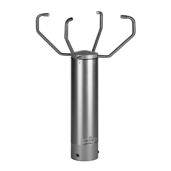
2. Mode of Operation
The Ultrasonic Anemometer 2D consists of 4 ultrasonic transducers, in pairs of 2 which are opposite each
other at a distance of 200 mm.
The two measurement paths thus formed are vertical to each other.
The transformers act both as acoustic transmitters and acoustic receivers.
The respective measurement paths and their measurement direction are selected via the electronic control.
When a measurement starts, a sequence of 4 individual measurements in all 4 directions of the
measurement paths is carried out at maximum possible speed.
The measurement directions (acoustic propagation directions) rotate clockwise, first from south to north, then
from west to east, from north to south and finally from east to west.
The mean values are formed from the 4 individual measurements of the path directions and used for further
calculations.
A measurement sequence takes approx. 10 msec at +20°C.
.
1. Range of Application
The Ultrasonic Anemometer 2D is designed to detect
the horizontal components of wind speed and wind
direction in two dimensions as well as the virtual
temperature. Due to its very short measurement
intervals, the instrument is ideal for the inertia-free
measurement of gusts and peak values.
In certain weather situations the accuracy of the air
temperature
measurement
surpasses that one of the classic method where the
temperature transmitter is used a weather and thermal
radiation shield.
The measured data are available as analogue signals
and as a data telegram via a serial interface. The
ultrasonic transducers as well as its carrying arms are
automatically heated so that the measuring results, in
case of critical ambient temperatures, are not affected
by icing rain or snow, and the risk of operation trouble,
caused by icing, is minimized.
1 - 10
(virtual-temperature)
021280/04/02
Advertisement
Table of Contents

Related Manuals for THIES Ultrasonic Anemometer 2D

Summary of Contents for THIES Ultrasonic Anemometer 2D
- Page 1 2. Mode of Operation The Ultrasonic Anemometer 2D consists of 4 ultrasonic transducers, in pairs of 2 which are opposite each other at a distance of 200 mm. The two measurement paths thus formed are vertical to each other.
-
Page 2: Measurement Principle
3. Measurement Principle 3.1 Wind speed and direction The speed of propagation of the sound in calm air is Wind from NNE superposed by the speed components of an air flow in wind direction. A wind speed component in the direction of the Y-Component propagation of the sound supports the speed of propagation, thus leading to an increase in the speed. -
Page 3: Technical Data
AC/DC, max. 70 VA Idling voltage when heating is switched-off: max. 32 V Protection IP 65 Icing according to THIES STD 012001 Corrosion No corrosion after 3 month of salt fog and condensation EN 55022 5/95 class B; EN50082-2 2/96 Model... - Page 4 6. Interface Description 6.1. Telegram „VESTAS“ ! I I V V V D D D S T T T B C R CHARACT.NO CHARACTER AVAILABLE FUNCTION 1 (!) Response character 2 (I) 0 ••• 9 Identifier Characters 3 (I) 0 ••• 9 Identifier characters 4 (V) 0 •••...
- Page 5 7. Averaging Procedure: The Ultrasonic 2D forms the gliding mean value through a FIFO-memory the capacity of which comprises up to 600 values. In the free running measurement mode the measurement data rate is exactly 10 Hz or 100msec, and forms, at the same time, the updating rate for the averaging memory (FIFO-memory).
- Page 6 8. Bus-Ability, Synchronisation of the Measurement on the Query Telegram: 8.1 Bus-Ability The Ultrasonic supports absolutely any operation at an RS485/RS422 data bus in co-operation with further instruments (bus operation). The line drivers of the ultrasonic are contemporarily active only for each transmission-period of the instrument.
- Page 7 9. List of control commands The Anemometer 2D can be controlled via its serial data interface using the commands in the following list. Any standard terminal program such as “procomm“ , “telix“ or a Windows terminal program (e.g. “Hyper Terminal” ) can be used. All adjustments are stored in a E²ROM so that the adjusted parameters cannot get lost after switching off or failure of power supply.
-
Page 8: Command Input
9.2 Command Input Please find your ID (identifier-number) in the works certificate included in the delivery. For the input of commands and parameters please open first the access to the EEPROM by entering the command (ID) KY00001. After all inputs have been made the access to the EEPROM should be locked again through the command (ID) KY00000 in order to avoid unauthorised changes of the system parameters. -
Page 9: Preparation For Use
10. Preparation for Use 10.1 Selecting the Site As already described above the ultrasonic anemometer transmits sonic bursts which are necessary for the measurement of the propagation speed. If these sonic bursts hit a well sonic-reflecting surface they are reflected as echo and might cause error measurements – under unfavourable conditions. It is, therefore, advisable to install the US-anemometer with a minimum distance of 1 meter to objects in the measurement area. -
Page 10: Maintenance
A return of the instruments must be effected in the original packing as otherwise the guarantee expires in case of mechanical damages e.g. by deformation of the transducer arms. ADOLF THIES GmbH & Co. KG Hauptstraße 76 37083 Göttingen Germany P.O.