Table of Contents
Advertisement
Quick Links
Advertisement
Table of Contents

Related Manuals for Fluke 7012

Summary of Contents for Fluke 7012
- Page 1 Hart Scientific 7012 Calibration Bath User Manual Rev. 992802...
- Page 2 Limited Warranty & Limitation of Liability Each product from Fluke Corporation, Hart Scientific Division ("Hart") is warranted to be free from de- fects in material and workmanship under normal use and service. The warranty period is one year for the Calibration Bath.
-
Page 3: Table Of Contents
Table of Contents 1 Before You Start ......1 Symbols Used ......1 Safety Information . - Page 4 8 General Operation ......27 Heat Transfer Fluid ......27 8.1.1 Temperature Range .
- Page 5 9.12 Serial Interface Parameters ..... 47 9.12.1 Baud Rate ........47 9.12.2 Sample Period.
- Page 6 Figures and Tables Figure 1 Bath Assembly ......9 Figure 2 Front Panel .
-
Page 7: Before You Start
1 Before You Start Symbols Used Before You Start Symbols Used Table 1 lists the International Electrical Symbols. Some or all of these symbols may be used on the instrument or in this manual. Table 1 International Electrical Symbols Symbol Description AC (Alternating Current) AC-DC... -
Page 8: Safety Information
7012 Calibration Bath User’s Guide Symbol Description Canadian Standards Association OVERVOLTAGE (Installation) CATEGORY II, Pollution Degree 2 per IEC1010-1 re- fers to the level of Impulse Withstand Voltage protection provided. Equipment of OVERVOLTAGE CATEGORY II is energy-consuming equipment to be supplied from the fixed installation. - Page 9 1 Before You Start Safety Information period of 2 hours before it can be assumed to meet all of the safety re- quirements of the IEC 1010-1. If the product is wet or has been in a wet environment, take necessary measures to remove moisture prior to apply- ing power such as storage in a low humidity temperature chamber operat- ing at 50 degree centigrade for 4 hours or more.
-
Page 10: Cautions
7012 Calibration Bath User’s Guide • The instrument is equipped with a soft cutout (user settable firmware) and a hard cutout (set at the factory). Check the flash point, boiling point, or other fluid characteristic applicable to the circumstances of the unit opera- tion. -
Page 11: Authorized Service Centers
Voltage Cut In: ±7.5 % (213 - 247 VAC) Authorized Service Centers Please contact one of the following authorized Service Centers to coordinate service on your Hart product: Fluke Corporation, Hart Scientific Division 799 E. Utah Valley Drive American Fork, UT 84003-9775 Phone: +1.801.763.1600 Telefax: +1.801.763.1010... - Page 12 22 Jianguomenwai Dajie Chao Yang District Beijing 100004, PRC CHINA Phone: +86-10-6-512-3436 Telefax: +86-10-6-512-3437 E-mail: xingye.han@fluke.com.cn Fluke South East Asia Pte Ltd. Fluke ASEAN Regional Office Service Center 60 Alexandra Terrace #03-16 The Comtech (Lobby D) 118502 SINGAPORE Phone: +65 6799-5588 Telefax: +65 6799-5588 E-mail: antng@singa.fluke.com...
- Page 13 1 Before You Start Authorized Service Centers • Voltage • Complete description of the problem...
-
Page 14: Introduction
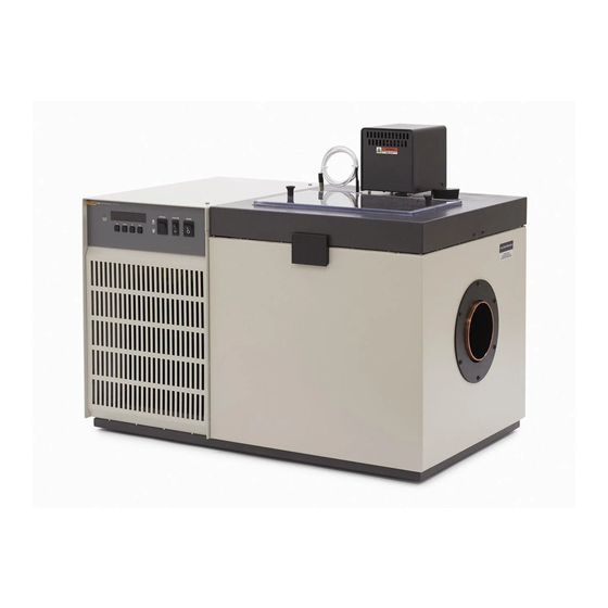
Digital remote communications is optionally available with a RS-232 or IEEE-488 interface. The tank for the 7012 is stainless steel and holds 36 liters. There are two lids available; the standard lid with a rectangular access hole and an optional lid with a recirculating pump (see Figure 5). -
Page 15: Specifications And Environmental Conditions
3 Specifications and Environmental Conditions Specifications Specifications and Environmental Conditions Specifications Range –10°C to 110°C (14°F to 230°F) Stability ±0.0008°C at 0°C (ethanol) ±0.0008°C at 25°C (water) ±0.003°C at 100°C (oil 5012) ±0.003°C at 0°C (ethanol) Uniformity ±0.002°C at 25°C (water) ±0.004°C at 100°C (oil 5012) Temperature Digital display with push-button data entry... -
Page 16: Environmental Conditions
7012 Calibration Bath User’s Guide Heater Fuse 115 VAC: 10 A 250 V fast blow 230 VAC: 6 A 250 V fast blow Safety OVERVOLTAGE (Installation) CATEGORY II, Pollution Degree 2 per IEC 61010-1 Environmental Conditions Although the instrument has been designed for optimum durability and trou- ble-free operation, it must be handled with care. -
Page 17: Quick Start
This section gives a brief summary of the steps required to set up and operate the 7012 bath. This should be used as a general overview and reference and not as a substitute for the remainder of the manual. Please read Section 5 through 7 carefully before operating the bath. -
Page 18: Power
7012 Calibration Bath User’s Guide Power Plug the bath power cord into a mains outlet of the proper voltage, frequency, and current capability. Refer to Section 3.1, Specifications, for power require- ment details. Refer to and read the WARNING at the front of this manual con- cerning brownout and over voltage protection. - Page 19 4 Quick Start Setting the Temperature Store new set-point, access vernier Current vernier value 0.00000 Press “EXIT” and the bath temperature is displayed again. Return to the temperature display Bath temperature display 24.73 C The bath heats or cools until it reaches the new set-point temperature. Set the heater switch to position “HIGH”...
-
Page 20: Installation
Bath Environment The Model 7012 Bath is a precision instrument which should be located in an appropriate environment. The location should be free of drafts, extreme temper- atures and temperature changes, dirt, etc. The surface where the bath is placed must be level. -
Page 21: Probe
7012 Calibration Bath User’s Guide • Water • Ethylene Glycol/Water • Methanol • Mineral oil • Silicone oil Fluids are discussed in detail in Section 8.1. Remove any access hole cover from the bath and check the tank for foreign matter (dirt, remnant packing material, etc.). -
Page 22: Bath Use
6 Bath Use General Bath Use READ BEFORE PLACING THE BATH IN SERVICE The information in this section is for general information only. It is not de- signed to be the basis for calibration laboratory procedures. Each laboratory will need to write their own specific procedures. General Be sure to select the correct fluid for the temperature range of the calibration. -
Page 23: Calibration Of Multiple Probes
7012 Calibration Bath User’s Guide these gradients are minimized inside the bath work area. Nevertheless, probes should be inserted to the same depth in the bath liquid. Be sure that all probes are inserted deep enough to prevent stem effect. From research at Hart Scien- tific, we suggest a general rule-of-thumb for immersion depth to reduce the stem effect to a minimum: 15 x the diameter of the UUT + the sensor length. -
Page 24: Parts And Controls
7 Parts and Controls Front Control Panel Parts and Controls Front Control Panel The following controls and indicators are present on the controller front panel (see Figure 2 below): (1) the digital LED display, (2) the control buttons, (3) the bath on/off power switch, (4) the control indicator light, (5) the heater power switch, and (6) the cooling power switch. -
Page 25: Side Panel
7012 Calibration Bath User’s Guide the heater is ON. When the indicator is green the heater is OFF and the bath is cooling. (5) The heater power switch is used to select the appropriate heater power lev- els for heating and controlling the bath at various temperatures. -
Page 26: Back Panel
7 Parts and Controls Back Panel 2) The cooling temperature regulating valve is used to adjust the tempera- ture at which the refrigerant evaporates, which determines cooling effi- ciency. Refer to the label below the gauge for approximate psi and evaporative temperature settings. -
Page 27: Bath Tank And Lid
7012 Calibration Bath User’s Guide Figure 4 Back Panel The serial number is located on the upper right corner of the back panel. When contacting an Authorized Service Center, use the serial number and model number. 6) If the bath is supplied with a serial RS-232 interface, the interface cable attaches to the back of the bath at the connector labeled “RS-232”. -
Page 28: Figure 5 Drain Location And Lid Options
7 Parts and Controls Bath Tank and Lid 1) The top half of the latch attaches the lid to the bath. There are two latches; one on the front and one on the back. 2) The thermometer/liquid level is a hole in the lid for filling and removing of liquid, checking liquid level, and for mounting a thermometer. - Page 29 7012 Calibration Bath User’s Guide 4) The stirrer/pump motor drives the stirring propellers to provide mixing of the bath fluid. Proper mixing of the fluid is important for good con- stant temperature stability and uniformity. The stir motor power cord plugs into the back of the bath at the power socket labeled “STIRRER”.
-
Page 30: General Operation
Heat Transfer Fluid General Operation Heat Transfer Fluid Many fluids will work with 7012 bath. Choosing a fluid requires consideration of many important characteristics of the fluid. Among these are temperature range, viscosity, specific heat, thermal conductivity, thermal expansion, electri- cal resistivity, fluid lifetime, safety, and cost. -
Page 31: Specific Heat
7012 Calibration Bath User’s Guide 8.1.3 Specific Heat Specific heat is the measure of the heat storage ability of the fluid. Specific heat, though to a lesser degree, also affects the control stability and the heating and cooling rates. Generally, a lower specific heat causes slightly better control stability and quicker heating and cooling. -
Page 32: Cost
8 General Operation Heat Transfer Fluid Fluids may be flammable and require special fire safety equipment and proce- dures. An important characteristic of the fluid to consider is the flash point. The flash point is the temperature at which there is sufficient vapor given off so that when there is sufficient oxygen present and an ignition source is applied the va- por will ignite. -
Page 33: Mineral Oil
7012 Calibration Bath User’s Guide low freeze point. Methanol is very toxic so care must be taken when using and disposing of this fluid. 8.1.10.4 Mineral Oil Mineral oil or paraffin oil is often used at moderate temperatures above the range of water. -
Page 34: About The Graph
8 General Operation Heat Transfer Fluid Figure 6 Chart of various bath fluids and their properties 8.1.11.2 About the Graph The fluid graph visually illustrates some of the important qualities of the fluids shown. Temperature Range: The temperature scale is shown in degrees Celsius. A sense of the fluid’s general range of application is indicated. -
Page 35: Table 2 Table Of Various Bath Fluids And Their Properties
7012 Calibration Bath User’s Guide Table 2 Table of various bath fluids and their properties Fluid Lower Upper Specific Heat Thermal Thermal (# = Hart Part Temperature Temperature Flash Viscosity Specific (cal/g/°C) Conductivity Expansion Resistivity Ω-cm ) No.) Limit* Limit*... -
Page 36: Stirring
8 General Operation Stirring Fume Point: The point at which a fume hood should be used. This point is very subjective in nature and is impacted by individual tolerance to different fumes and smells, how well the bath is covered, the surface area of the fluid in the bath, the size and ventilation of the facility where the bath is located and others. -
Page 37: Cooling
7012 Calibration Bath User’s Guide The front panel red/green control indicator shows the state of the heater. The control indicator glows red when the heater is on and glows green when the heater is off. The indicator will pulse constantly when the bath is maintaining a stable temperature. - Page 38 8 General Operation Temperature Controller signal, amplified, and then fed to a pulse-width modulator circuit which con- trols the amount of power applied to the bath heater. The bath is operable within the temperature range given in the specifications. For protection against solid-state relay failure or other circuit failure, the microcontroller automatically turns off the heater with a second mechanical re- lay anytime the bath temperature is more than a certain amount above the set-point temperature.
-
Page 39: Controller Operation
9 Controller Operation Bath Temperature Controller Operation This section discusses in detail how to operate the bath temperature controller using the front control panel. Using the front panel key switches and LED dis- play the user may monitor the bath temperature, set the temperature set-point in degrees C or F, monitor the heater output power, adjust the controller propor- tional band, set the cutout set-point, and program the probe calibration parame- ters, operating parameters, serial and IEEE-488 interface configuration, and... -
Page 40: Figure 7 Controller Operation Flowchart
7012 Calibration Bath User’s Guide Figure 7 Controller Operation Flowchart... -
Page 41: Temperature Set-Point
9 Controller Operation Temperature Set-point Cutout reset function rESEt ? Press “SET” once more to reset the cutout. Reset cutout This switchs the display to the set temperature function. To return to displaying the temperature press the “EXIT” button. If the cutout is still in the over-tem- perature fault condition the display continues to flash “Cut-out”. -
Page 42: Set-Point Value
7012 Calibration Bath User’s Guide Accept selected set-point memory 9.3.2 Set-point Value The set-point value may be adjusted after selecting the set-point memory and pressing “SET”. The set-point value is displayed with the units, C or F, at the left. -
Page 43: Temperature Scale Units
9 Controller Operation Temperature Scale Units Access scale units Temperature Scale Units The temperature scale units of the controller may be set by the user to degrees Celsius (°C) or Fahrenheit (°F). These units are used in displaying the bath temperature, set-point, vernier, proportional band, and cutout set-point. -
Page 44: Secondary Menu
7012 Calibration Bath User’s Guide Secondary Menu Functions which are used less often are accessed within the secondary menu. The secondary menu is accessed by pressing “SET” and “EXIT” simulta- neously and then releasing. The first function in the secondary menu is the heater power display. -
Page 45: Proportional Band - Fluid Table
9 Controller Operation Proportional Band tional band is too narrow the bath temperature may swing back and forth be- cause the controller overreacts to temperature variations. For best control stability the proportional band must be set for the optimum width. Figure 8 Bath temperature fluctuation at various proportional band settings The optimum proportional band width depends on several factors among which are fluid volume, fluid characteristics (viscosity, specific heat, thermal conduc-... -
Page 46: Cutout
7012 Calibration Bath User’s Guide The proportional band should also be wider when the fluid viscosity is higher because of the increased response time. The proportional band width is easily adjusted from the bath front panel. The width may be set to discrete values in degrees C or F depending on the selected units. -
Page 47: Controller Configuration
9 Controller Operation Controller Configuration of the fluid and no more than 10 degrees above the upper temperature limit of the bath. If the cutout is activated because of excessive bath temperature, power to the heater shuts off and the bath cools. The bath cools until it reaches a few degrees below the cutout set-point temperature. -
Page 48: Probe Parameters
7012 Calibration Bath User’s Guide “SET.” There are 5 sets of configuration parameters — probe parameters, oper- ating parameters, serial interface parameters, IEEE-488 interface parameters, and controller calibration parameters. The menus are selected using the “UP” and “DOWN” keys and then pressing “SET”. -
Page 49: Serial Interface Parameters
Cto=Auto Cutout set for automatic reset 9.12 Serial Interface Parameters The 7012 bath may optionally be fitted with an RS-232 interface. The serial RS-232 interface parameters menu is indicated by, Serial RS-232 interface parameters menu SErIAL The serial interface parameters menu contains parameters which determine the operation of the serial interface. -
Page 50: Sample Period
7012 Calibration Bath User’s Guide 9.12.2 Sample Period The sample period is the next parameter in the serial interface parameter menu. The sample period is the time period in seconds between temperature measure- ments transmitted from the serial interface. If the sample rate is set to 5, the bath transmits the current measurement over the serial interface approximately every five seconds. -
Page 51: Ieee-488 Parameters
9 Controller Operation IEEE-488 Parameters Press “SET” to access the linefeed parameter. Current linefeed setting LF= On The mode may be changed using “UP” or “DOWN” and pressing “SET”. New linefeed setting LF= OFF 9.13 IEEE-488 Parameters Baths may optionally be fitted with an IEEE-488 GPIB interface. In this case the user may set the interface address within the IEEE-488 parameter menu. -
Page 52: Cto
9.14.1 Parameter CTO sets the calibration of the over-temperature cutout. This is not adjustable by software but is adjusted with an internal potentiometer. For the 7012 baths this parameter should read between 120. 9.14.2 H and L These parameters set the upper and lower set-point limits of the bath. DO NOT change the values of these parameters from the factory set values. -
Page 53: Digital Communication Interface
Serial Communications Digital Communication Interface If supplied with the option, the 7012 bath is capable of communicating with and being controlled by other equipment through the digital interface. Two types of digital interface are available — the RS-232 serial interface and the IEEE-488 GPIB interface. -
Page 54: Baud Rate
PLE”. The sample period is the time period in seconds between temperature measurements transmitted from the serial interface. If the sample rate is set to 5, the 7012 transmits the current measurement over the serial interface approxi- mately every five seconds. The automatic sampling is disabled with a sample period of 0. -
Page 55: Serial Operation
10 Digital Communication Interface IEEE-488 Communication 10.1.3 Serial Operation Once the cable has been attached and the interface set up properly the control- ler immediately begins transmitting temperature readings at the programmed rate. The set-point and other commands may be sent to the bath via the serial interface to set the bath and view or program the various parameters. -
Page 56: Interface Command Summary
7012 Calibration Bath User’s Guide Table 4 Interface Command Summary. Command Command Returned Acceptable Command Description Format Example Returned Example Values Display Temperature Read current set-point s[etpoint] set: 9999.99 {C or F} set: 105.00 C Set current set-point to n... -
Page 57: Digital Communications Commands Continued
10 Digital Communication Interface Interface Commands Digital Communications Commands continued Command Command Returned Acceptable Command Description Format Example Returned Example Values Set serial sampling setting to n sa[mple]=n sa=0 0 to 4000 seconds FULL or HALF Set serial duplex mode: du[plex]=f[ull]/h[alf] Set serial duplex mode to full du[plex]=f[ull]... -
Page 58: Power Control Functions
1) switching the heater switch to LOW, and 2) switching the refrigeration switch to OFF. Otherwise, the interface would not be able to switch these functions off. The 7012 bath has four control functions with the digital interface. These are heater power high/low, cooling on/off, ex- pansion valve on/off, and back pressure valve on/off. -
Page 59: Temperature Range Control Functions
10 Digital Communication Interface Power Control Functions beled “HIGH” controls the cooling temperature when the expansion valve is open or on. This should be adjusted for approximately 45–50 psi. These values are typical but may be adjusted as required for specific applications. The low range must be set to a lower pressure (temperature) than the high range valve. -
Page 60: Calibration Procedure
11 Calibration Procedure Calibration Points Calibration Procedure Note: This procedure is to be considered a general guideline. Each labo- ratory should write their own procedure based on their equipment and their quality program. Each procedure should be accompanied by an un- certainty analysis also based on the laboratory’s equipment and environ- ment. -
Page 61: Computing D0 And Dg
7012 Calibration Bath User’s Guide the bath was set for 80°C and the thermometer measured 80.1°C giving an error of +0.1°C. 11.3 Computing D0 and DG Before computing the new values for D0 and DG the current values must be known. -
Page 62: Figure 10 Sample Calibration Computations
11 Calibration Procedure Calibration Example D0 = -25.229 DG = 186.974 = 25.00°C measured t = 24.869°C = 75.00°C measured t = 74.901°C Compute errors, = 24.869 - 25.00°C = -0.131°C = 74.901 - 75.00°C = -0.099°C Compute D0, − −... -
Page 63: Maintenance
12 Maintenance Maintenance The calibration instrument has been designed with the utmost care. Ease of op- eration and simplicity of maintenance have been a central theme in the product development. Therefore, with proper care the instrument should require very little maintenance. Avoid operating the instrument in dirty or dusty environments. -
Page 64: Draining The Bath
7012 Calibration Bath User’s Guide • If the mains supply cord becomes damaged, replace it with a cord with the appropriate gauge wire for the current of the bath. If there are any questions, contact an Authorized Service Center for more information. - Page 65 12 Maintenance Draining the Bath High viscosity oils - The fluid should be sufficiently low in viscosity to drain efficiently. Some oils such as 710 silicone oil may need to be heated to 80°C to be fluid enough to drain well. The viscosity affects how rapidly it drains as well as how well it flows off of the walls.
-
Page 66: Troubleshooting
13 Troubleshooting Troubleshooting Troubleshooting This section contains information on troubleshooting and CE Comments. This information pertains to a number of bath models and certain specifics may not pertain to your model. 13.1 Troubleshooting In the event that the instrument appears to function abnormally, this section may help to find and solve the problem. - Page 67 7012 Calibration Bath User’s Guide Problem Causes and Solutions The display flashes “cutout” and The problem may be that the controller’s voltmeter circuit is not func- an incorrect process temperature tioning properly. • A problem could exist with the memory back-up battery.
- Page 68 13 Troubleshooting Troubleshooting Problem Causes and Solutions The controller controls or at- The controller operates normally except when controlling at a speci- tempts to control at an inaccurate fied set-point. At this set-point, the temperature displayed does not temperature agree with the temperature measured by the user’s reference ther- mometer to within the specified accuracy.
-
Page 69: Comments
7012 Calibration Bath User’s Guide Problem Causes and Solutions The bath does not achieve low Too much heating or not enough cooling can cause this problem. temperatures • Check that the control indicator glows green showing that the controller is attempting to cool. The heaters may be disabled as a test by temporarily removing the heater fuses.