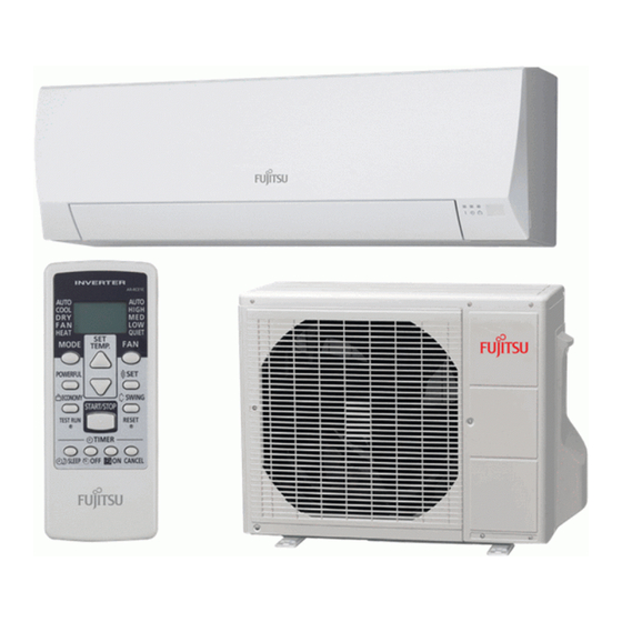
Fujitsu ASYG07LLCE Design & Technical Manual
Hide thumbs
Also See for ASYG07LLCE:
- Service manual (18 pages) ,
- Service manual (60 pages) ,
- Service instruction (60 pages)

Related Manuals for Fujitsu ASYG07LLCE


Summary of Contents for Fujitsu ASYG07LLCE
-
Page 1: Wall Mounted Type
AIR CONDITIONER Wall mounted type DESIGN & TECHNICAL MANUAL INDOOR ASYG07LLCE ASYG09LLCE ASYG12LLCE OUTDOOR AOYG07LLCE AOYG09LLCE AOYG12LLCE DR_AS036EF_02 2016.04.06... - Page 2 Notices: • Product specifications and design are subject to change without notice for future improvement. • For further details, please check with our authorized dealer. Copyright © 2016, 2017 Fujitsu General Limited. All rights reserved.
-
Page 3: Table Of Contents
CONTENTS Part 1. INDOOR UNIT............... 1 1. Specifications.................... 2 2. Dimensions....................4 2-1. Models:ASYG07LLCE, ASYG09LLCE, and ASYG12LLCE........4 3. Wiring diagrams ..................6 3-1. Models:ASYG07LLCE, ASYG09LLCE, and ASYG12LLCE........6 4. Capacity table.................... 7 4-1. Cooling capacity......................7 4-2. Heating capacity ......................8 5. - Page 4 CONTENTS (continued) Part 2. OUTDOOR UNIT..............23 1. Specifications..................24 2. Dimensions....................25 2-1. Models:AOYG07LLCE, AOYG09LLCE, and AOYG12LLCE........25 3. Installation space ..................26 3-1. Models:AOYG07LLCE, AOYG09LLCE, and AOYG12LLCE........26 4. Refrigerant circuit ................... 29 4-1. Models:AOYG07LLCE, AOYG09LLCE, and AOYG12LLCE........29 5.
-
Page 5: Part 1. Indoor Unit
Part 1. INDOOR UNIT WALL MOUNTED TYPE: ASYG07LLCE ASYG09LLCE ASYG12LLCE... -
Page 6: Specifications
1. Specifications Wall mounted Type Inverter heat pump Model name ASYG07LLCE ASYG09LLCE ASYG12LLCE Power supply 230 V ~ 50 Hz Available voltage range 198—264 V 2.00 2.50 3.40 Rated Btu/h 6,800 8,500 11,600 Cooling 0.9—2.8 0.9—3.0 0.9—3.8 Min.—Max. Btu/h 3,100—9,500 3,100—10,200... - Page 7 Model name ASYG07LLCE ASYG09LLCE ASYG12LLCE Cooling Energy efficiency class Heating (Average) Cooling 2.0 (35 °C) 2.5 (35 °C) 3.4 (35 °C) Pdesign Heating (Average) 2.2 (-10 °C) 2.3 (-10 °C) 3.2 (-10 °C) SEER Cooling 6.70 6.90 6.60 kWh/kWh SCOP Heating (Average) 4.00...
-
Page 8: Dimensions
2. Dimensions 2-1. Models:ASYG07LLCE, ASYG09LLCE, and ASYG12LLCE Unit: mm (820) Outline of unit - 4 -... - Page 9 ¢ Installation space requirement Provide sufficient installation space for product safety. Unit: mm Outline of unit 70 or more 100 or more 1,500 or more - 5 -...
-
Page 10: Wiring Diagrams
3. Wiring diagrams 3-1. Models:ASYG07LLCE, ASYG09LLCE, and ASYG12LLCE - 6 -... -
Page 11: Capacity Table
Airflow Rate (AFR): For cooling capacity: Total Capacity (TC), Sensible Heat Capacity (SHC), and Input Power (IP) For heating capacity: Total Capacity (TC) and Input Power (IP) 4-1. Cooling capacity ¢ Model:ASYG07LLCE Indoor temperature °CDB °CWB °CDB... -
Page 12: Heating Capacity
4-2. Heating capacity ¢ Model:ASYG07LLCE Indoor temperature °CDB °CWB 2.42 1.22 2.36 1.24 2.30 1.27 2.24 1.30 2.19 1.32 2.51 1.17 2.45 1.20 2.39 1.22 2.33 1.24 2.27 1.27 2.75 1.15 2.68 1.18 2.61 1.20 2.55 1.23 2.48 1.25 3.18 1.18... -
Page 13: Fan Performance
5. Fan performance 5-1. Air velocity distributions ¢ Models:ASYG07LLCE, ASYG09LLCE, and ASYG12LLCE Fan speed Operation mode Measuring conditions HIGH Unit: m/s Top view Vertical airflow direction louver: Up Horizontal airflow direction louver: Center Unit: m/s Top view Vertical airflow direction louver: Up Horizontal airflow direction louver: Left &... -
Page 14: Airflow
5-2. Airflow ¢ Models:ASYG07LLCE, ASYG09LLCE, and ASYG12LLCE Cooling Fan speed Airflow HIGH QUIET Heating Fan speed Airflow HIGH QUIET - 10 -... -
Page 15: Operation Noise (Sound Pressure)
6. Operation noise (sound pressure) 6-1. Noise level curve ¢ Models:ASYG07LLCE and ASYG09LLCE Cooling Heating NC-65 NC-65 NC-60 NC-60 NC-55 NC-55 NC-50 NC-50 NC-45 NC-45 HIGH HIGH NC-40 NC-40 NC-35 NC-35 NC-30 NC-30 NC-25 NC-25 NC-20 NC-20 QUIET... -
Page 16: Sound Level Check Point
6-2. Sound level check point Microphone Microphone - 12 -... -
Page 17: Safety Devices
7. Safety devices Model Type of Protection form protection ASYG07LLCE ASYG09LLCE ASYG12LLCE Circuit protection Current fuse (PCB*) 250 V, 3.15 A 93±5 °C Activate Fan motor speed down Fan motor Thermistor protection protection program 93±5 °C Reset Fan motor speed recover... -
Page 18: Remote Controller
8. Remote controller 8-1. Wireless remote controller ¢ Overview a FAN button b SET button c SWING button d START/STOP button e RESET button f TIMER CANCEL button g ON TIMER button h OFF TIMER button i SLEEP TIMER button j TEST RUN button •... - Page 19 NOTE: Functions may differ by type of the indoor unit. For details, refer to the operation manual. - 15 -...
- Page 20 ¢ Specifications Controller Unit: mm Top view Front view Side view Rear view Size (H × W × D) 139 × 56 × 18 Weight 70 (without batteries) Holder Unit: mm 60.4 30.2 Ø 3.5 (hole) 3.5 x 6.5 (hole) 26.2 Front view...
-
Page 21: Function Settings
9. Function settings To adjust the functions of this product according to the installation environment, various types of function settings are available. NOTE: Incorrect settings can cause a product malfunction. 9-1. Function settings by using remote controller Some function settings can be changed on the remote controller. After confirming the setting pro- cedure and the content of each function setting, select appropriate functions for your installation environment. - Page 22 NOTES: • The air conditioner custom code is set to prior to shipment. To change the custom code, contact your retailer. • The remote controller resets to custom code when the batteries on the remote controller are replaced. If you use a custom code other than code , reset the custom code after replacing the batteries.
- Page 23 ¢ Contents of function setting Each function setting listed in this section is adjustable in accordance with the installation environ- ment. NOTE: Setting will not be changed if invalid numbers or setting values are selected. Function setting list Function no. Functions Filter sign Room temperature sensor control for cooling...
- Page 24 4) Auto restart Enables or disables automatic restart after a power interruption. Function number Setting value Setting description Factory setting Enable ♦ Disable NOTE: Auto restart is an emergency function such as for power outage etc. Do not attempt to use this function in normal operation.
-
Page 25: Custom Code Setting For Wireless Remote Controller
9-2. Custom code setting for wireless remote controller To interconnect the air conditioner and the wireless remote controller, assignment of the custom code for the wireless remote controller is required. NOTE: Air conditioner cannot receive a custom code if the air conditioner has not been set for the custom code. -
Page 26: Accessories
10. Accessories Part name Exterior Q’ty Part name Exterior Q’ty Operating manual Battery Installation manual Cloth tape Tapping screw (large), Wall hook bracket M4 × 25 mm Remote controller - 22 -... -
Page 27: Part 2. Outdoor Unit
Part 2. OUTDOOR UNIT SINGLE TYPE: AOYG07LLCE AOYG09LLCE AOYG12LLCE... -
Page 28: Specifications
1. Specifications Type Inverter heat pump Model name AOYG07LLCE AOYG09LLCE AOYG12LLCE Power supply 230 V ~ 50 Hz Available voltage range 198—264 V Starting current Cooling 1,670 1,830 Airflow rate Heating 1,470 1,600 Type × Q'ty Propeller fan × 1 Motor output Cooling Sound pressure level *1... -
Page 29: Dimensions
2. Dimensions 2-1. Models:AOYG07LLCE, AOYG09LLCE, and AOYG12LLCE Unit: mm Drain hole 30 (Pitch of bolt) Top view Front view Side view - 25 -... -
Page 30: Installation Space
3. Installation space 3-1. Models:AOYG07LLCE, AOYG09LLCE, and AOYG12LLCE ¢ Space requirement Provide sufficient installation space for product safety. Single outdoor unit installation • When the upper space is open: Unit: mm When there are obstacles at the rear only. When there are obstacles at the rear and sides. - Page 31 Multiple outdoor unit installation • When the upper space is open: Unit: mm When there are obstacles at the rear only. When there are obstacles at the front only. 1,000 or more or more When there are obstacles at the front and rear.
- Page 32 Outdoor unit installation in multi-row Unit: mm Single parallel unit arrangement Multiple parallel unit arrangement 100 or more 200 or more 1,000 or more 2,000 or more 200 or more 400 or more 1,000 or more 500 or more 200 or more NOTES: •...
-
Page 33: Refrigerant Circuit
4. Refrigerant circuit 4-1. Models:AOYG07LLCE, AOYG09LLCE, and AOYG12LLCE Heat exchanger 3-way (INDOOR) valve 2-way valve Muffler 4-way valve Strainer Expansion valve Strainer : Cooling : Heating : Thermistor (Discharge temperature) : Thermistor (Outdoor temperature) : Thermistor (Heat exchanger out temperature) : Thermistor (Room temperature) : Thermistor (Pipe temperature) - 29 -... -
Page 34: Wiring Diagrams
5. Wiring diagrams 5-1. Models:AOYG07LLCE, AOYG09LLCE, and AOYG12LLCE - 30 -... -
Page 35: Capacity Compensation Rate For Pipe Length And Height Difference
6. Capacity compensation rate for pipe length and height difference Height difference H Indoor unit is higher than outdoor unit Indoor unit is lower than outdoor unit Outdoor unit Indoor unit Outdoor unit Indoor unit Connection pipe Connection pipe 6-1. Models:AOYG07LLCE and AOYG09LLCE NOTE: Values mentioned in the table are calculated based on the maximum capacity. -
Page 36: Model:aoyg12Llce
6-2. Model:AOYG12LLCE NOTE: Values mentioned in the table are calculated based on the maximum capacity. Pipe length (m) COOLING 0.858 0.868 0.929 0.872 0.882 Indoor unit is higher than outdoor unit *1 0.960 0.933 0.876 0.885 0.992 0.964 0.937 0.879 0.889 1.000 0.972... -
Page 37: Additional Charge Calculation
7. Additional charge calculation 7-1. Models:AOYG07LLCE and AOYG09LLCE Refrigerant type R410A Refrigerant amount ¢ Refrigerant charge Total pipe length 15 or less 20 (Max.) 20 g/m Additional charge 7-2. Model:AOYG12LLCE Refrigerant type R410A Refrigerant amount ¢ Refrigerant charge Total pipe length 15 or less 20 (Max.) 20 g/m... -
Page 38: Airflow
8. Airflow 8-1. Models:AOYG07LLCE and AOYG09LLCE Cooling 1,670 Heating 1,470 8-2. Model:AOYG12LLCE Cooling 1,830 1,077 Heating 1,600 - 34 -... -
Page 39: Operation Noise (Sound Pressure)
9. Operation noise (sound pressure) 9-1. Noise level curve ¢ Model:AOYG07LLCE Cooling Heating NC-65 NC-65 NC-60 NC-60 NC-55 NC-55 NC-50 NC-50 NC-45 NC-45 NC-40 NC-40 NC-35 NC-35 NC-30 NC-30 NC-25 NC-25 NC-20 NC-20 NC-15 NC-15 1,000 2,000 4,000 8,000 1,000 2,000... - Page 40 ¢ Model:AOYG12LLCE Cooling Heating NC-65 NC-65 NC-60 NC-60 NC-55 NC-55 NC-50 NC-50 NC-45 NC-45 NC-40 NC-40 NC-35 NC-35 NC-30 NC-30 NC-25 NC-25 NC-20 NC-20 NC-15 NC-15 1,000 2,000 4,000 8,000 1,000 2,000 4,000 8,000 Octave band center frequency,Hz Octave band center frequency,Hz - 36 -...
-
Page 41: Sound Level Check Point
9-2. Sound level check point Rear Microphone Microphone Airflow Side view Rear view NOTE: Detailed shape of the actual outdoor unit might be slightly different from the one illustrat- ed above. - 37 -... -
Page 42: Electrical Characteristics
10. Electrical characteristics Model name AOYG07LLCE AOYG09LLCE AOYG12LLCE Voltage 230 ~ Power supply Frequency Max operating current *1 Starting current Circuit breaker current Power cable Wiring spec. *2 Connection cable *3 Limited wiring length *1: Maximum current is the total current of the indoor unit and the outdoor unit. *2: Selected sample based on Japan Electrotechnical Standards and Codes Committee E0005. -
Page 43: Safety Devices
11. Safety devices Model Type of Protection form protection AOYG07LLCE AOYG09LLCE AOYG12LLCE 250 V, 25 A Circuit protection Current fuse (Main PCB) 250 V, 5 A 100±15 °C Activate Fan motor stop Fan motor Terminal protection protection program 95±10 °C Reset Fan motor restart 110 °C... -
Page 44: Accessories
12. Accessories Part name Exterior Q’ty Part name Exterior Q’ty Drain pipe - 40 -...