
Related Manuals for Dell OptiPlex 5055


Summary of Contents for Dell OptiPlex 5055
- Page 1 Dell OptiPlex 5055 Small Form Factor Owner's Manual Regulatory Model: D11S Regulatory Type: D11S003...
- Page 2 A WARNING indicates a potential for property damage, personal injury, or death. © 2017 Dell Inc. or its subsidiaries. All rights reserved. Dell, EMC, and other trademarks are trademarks of Dell Inc. or its subsidiaries. Other trademarks may be trademarks of their respective owners.
-
Page 3: Table Of Contents
Contents 1 Working on your computer..........................6 Safety instructions................................6 Turning off your computer..............................6 Turning off your computer — Windows 10.......................6 Before working inside your computer..........................7 After working inside your computer..........................7 2 Chassis................................8 Front chassis view................................8 Back chassis view – Ryzen Pro CPU..........................9 Back chassis view –... - Page 4 Processor..................................27 Removing the processor............................27 Installing the processor..............................28 Intrusion switch................................29 Removing intrusion switch............................29 Installing intrusion switch............................30 Memory modules................................30 Removing memory module............................30 Installing memory module............................30 SD card....................................31 Removing SD card reader............................31 Installing SD card reader............................31 Power supply unit................................32 Removing power supply unit —...
- Page 5 6 Troubleshooting............................59 Enhanced Pre-Boot System Assessment — ePSA diagnostics................59 Contents...
-
Page 6: Working On Your Computer
Damage due to servicing that is not authorized by Dell is not covered by your warranty. Read and follow the safety instructions that came with the product. -
Page 7: Before Working Inside Your Computer
NOTE: Ensure that the computer and all attached devices are turned off. If your computer and attached devices did not automatically turn off when you shut down your operating system, press and hold the power button for about 6 seconds to turn them off. -
Page 8: Chassis
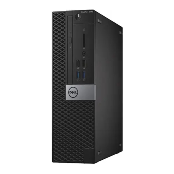
Chassis Front chassis view Power button and power light Hard drive activity light Memory card reader (optional) Optical drive (optional) Headset port USB 2.0 port with PowerShare USB 2.0 port USB 3.1 Gen1 port Chassis... -
Page 9: Back Chassis View - Ryzen Pro Cpu
Back chassis view – Ryzen Pro CPU Line-out port DisplayPort Serial port PS/2 keyboard port USB 3.0 ports USB 2.0 ports (supports Smart Power On) Expansion card slots Power connector port Power supply diagnostic light Kensington security cable slot Network port PS/2 mouse port DisplayPort Release latch... -
Page 10: Back Chassis View - Radeon R7 A Series Apu
Back chassis view – Radeon R7 A series APU Line-out port DisplayPort Serial port PS/2 keyboard port USB 3.0 ports USB 2.0 ports (supports Smart Power On) Expansion card slots Power connector port Power supply diagnostic light Kensington security cable slot Network port PS/2 mouse port DisplayPort... -
Page 11: Removing And Installing Components
Removing and installing components This section provides detailed information on how to remove or install the components from your computer. Recommended tools The procedures in this document require the following tools: • Small flat blade screwdriver • Phillips # 1 screwdriver •... - Page 12 Lift the cover to remove it from the computer. Removing and installing components...
-
Page 13: Installing Cover
Installing cover Place the cover on the computer and slide the cover forward until it clicks into place. Follow the procedure in After working inside your computer. Front Bezel Removing the front bezel Follow the procedure in Before working inside your computer. -
Page 14: Installing Front Bezel
Installing front bezel Insert the tabs of the bezel into the slots on the chassis. Press the bezel until the tabs click into place. Install the cover. Follow the procedure in After working inside your computer. Storage device Removing 2.5–inch hard drive assembly Follow the procedure in Before working inside your computer. - Page 15 Slide and lift the hard drive assembly from the computer. Removing and installing components...
-
Page 16: Removing 2.5-Inch Hard Drive From The Hard Drive Bracket
Removing 2.5–inch hard drive from the hard drive bracket Follow the procedure in Before working inside your computer. Remove the: cover 2.5 inch hard drive assembly To remove hard drive bracket: Pull one side of the hard drive bracket to disengage the pins on the bracket from the slots on the hard drive [1]. b Lift the drive out of the 2.5-inch drive bracket [2]. -
Page 17: Installing 2.5-Inch Hard Drive Into The Hard Drive Bracket
Installing 2.5–inch hard drive into the hard drive bracket Flex the side of the hard drive bracket, to align and insert the pins on the bracket into the hard drive. Insert the hard drive into the hard drive bracket until it clicks into place. Install the: 2.5 inch hard drive assembly cover... - Page 18 To remove the PCIe expansion card: Pull the release latch to unlock the PCIe expansion card [1]. b Push the release tab [2] and lift the PCIe expansion card out of the computer [3]. NOTE: The release tab is at the base of the expansion card. Removing and installing components...
-
Page 19: Installing Pcie Expansion Card
Repeat the steps to remove any additional PCIe expansion cards. Installing PCIe expansion card Insert the expansion card into the connector on the system board. Press the expansion card until it clicks into place. Close the expansion card latch and press it until it clicks into place. Install the: front bezel cover... - Page 20 NOTE: Illustration on how to remove the shroud is also given on the shroud. b Lift the cooling shroud away from the chassis. Removing and installing components...
-
Page 21: Installing Cooling Shroud
Installing cooling shroud NOTE: When inserting the shroud on the processor assembly, please ensure that the data and power cables of the optical drive do not get caught inside the shroud. Align the slots on the cooling shroud, with the screws on the heat sink. Insert the cooling shroud over the processor assembly. -
Page 22: Installing Coin Cell Battery
b Remove the coin cell battery from the connector on the system board [2]. Installing coin cell battery Hold the coin cell battery with the "+" sign facing up and slide it under the securing tabs at the positive side of the connector. Press the battery into the connector until it locks into place. - Page 23 2.5 inch hard drive assembly To remove optical drive: Release the cables from the retention clip [1]. b Slide the blue tab to unlock the optical drive assembly [2]. To remove the optical drive assembly: Pull the tab upward to release the assembly [1]. b Holding the tab, disconnect the optical drive cables [2].
-
Page 24: Installing Optical Drive
NOTE: After releasing the Optical drive, you can also flip the drive assembly for easy access to the drive cables. NOTE: The Optical drive cables are available on side of the drive assembly. To remove the optical drive: Slide the tab to release the optical drive [1]. b Push the optical drive away from the assembly [2][3]. -
Page 25: M.2 Pcie Ssd
cooling shroud front bezel cover Follow the procedure in After working inside your computer. M.2 PCIe SSD Removing M.2 PCIe SSD Follow the procedure in Before working inside your computer. Remove the: cover front bezel 2.5 inch hard drive assembly cooling shroud optical drive To remove the M.2 PCIe SSD:... -
Page 26: Installing M.2 Pcie Ssd
Installing M.2 PCIe SSD Insert the M.2 PCIe SSD to the connector Press the blue plastic tab to secure the M.2 PCIe SSD. Install the: optical drive cooling shroud 2.5 inch hard drive assembly front bezel cover Follow the procedure in After working inside your computer. -
Page 27: Installing Heat Sink Assembly
Installing heat sink assembly Align the screws of the heat sink assembly with the holders on the system board. Place the heat sink assembly on the processor. Replace the captive screws (6 lbs) to secure the heat sink assembly to the system board. NOTE: Tighten the screws based on the order given in the system board. -
Page 28: Installing The Processor
cover front bezel 2.5 hard drive assembly cooling shroud optical drive heat sink assembly To remove the processor: Release the socket lever by pushing the lever down and out from under the tab on the processor shield [1]. b Lift the lever upward and lift the processor shield [2]. Lift the processor out of the socket [3]. -
Page 29: Intrusion Switch
Install the: heat sink assembly optical drive cooling shroud 2.5 hard drive assembly front bezel cover Follow the procedure in After working inside your computer. Intrusion switch Removing intrusion switch Follow the procedure in Before working inside your computer. Remove the: cover front bezel cooling shroud... -
Page 30: Installing Intrusion Switch
Installing intrusion switch Insert the intrusion switch into the slot on the computer. Connect the intrusion switch cable to the connector on the system board. Install the: cooling shroud front bezel cover Follow the procedure in After working inside your computer. -
Page 31: Sd Card
SD card Removing SD card reader Follow the procedure in Before working inside your computer. Remove the: cover front bezel 2.5 inch hard drive assembly cooling shroud optical drive M.2 PCIe SSD To remove the SD card reader: Release the power cables from the retention clips on the SD card reader enclosure [1]. b Remove the screws(6lbs) that secure the SD card reader [2]. -
Page 32: Power Supply Unit
Install the: M.2 PCIe SSD optical drive cooling shroud 2.5 inch hard drive assembly front bezel cover Follow the procedure in After working inside your computer. Power supply unit Removing power supply unit — PSU Follow the procedure in Before working inside your computer. - Page 33 To disconnect the cables: Disconnect the power cable from the system board [1] [2]. b Lift the cables away from the computer [3, 4]. Remove the screws(6lbs) that secure the PSU to the computer [5]. To remove the PSU: Press the blue release tab [1] b Slide the PSU and lift it away from the computer [2].
-
Page 34: Installing Power Supply Unit - Psu
Installing power supply unit — PSU Insert the PSU into the slot. Slide the PSU towards the back of the computer until it clicks into place. Replace the screws( 6lbs) to secure the PSU to the computer. Route the PSU cables through the retention clips. Connect the PSU cables to the connectors on the system board. -
Page 35: Installing Power Switch
cover front bezel 2.5 inch hard drive assembly cooling shroud optical drive To release the power switch: Disconnect the power switch cable from the system board [1]. b Press the power switch retention tabs and pull out from the computer [2, 3]. Installing power switch Slide the power switch module into the slot on the chassis until it clicks into place. -
Page 36: Speaker
cover Follow the procedure in After working inside your computer. Speaker Removing speaker Follow the procedure in Before working inside your computer. Remove the: cover front bezel 2.5 inch hard drive assembly cooling shroud optical drive To remove the speaker: Disconnect the speaker cable from the connector on the system board [1]. -
Page 37: System Board
Install the: optical drive cooling shroud 2.5 inch hard drive assembly front bezel cover Follow the procedure in After working inside your computer. System board Removing the system board Follow the procedure in Before working inside your computer. Remove the: cover front bezel 2.5 inch hard drive assembly... - Page 38 Disconnect the following cables and screw from the system board: PSU [1] b hard drive and optical drive caddy stand off screw [2] PSU [3] d power switch [4] intrusion switch [5] Removing and installing components...
- Page 39 To remove the I/O panel plate: Remove the screw (6 lbs) that secures the I/O panel [1]. b Slide and push toward the front from the computer [2]. Removing and installing components...
- Page 40 To remove the system board: Remove the screws (12 lbs) that secure the system board to the computer b Slide and lift the system board away from the computer [2]. Removing and installing components...
-
Page 41: Installing The System Board
Installing the system board Hold the system board by its edges and align it toward the back of the computer. Lower the system board into the chassis until the connectors at the back of the system board. Align with the slots on the chassis, and the screw holes on the system board align with the standoffs on the computer. Replace the screws (12 lbs) to secure the system board to the computer. - Page 42 memory module heat sink assembly SD card M.2 PCIe SSD processor cooling shroud optical drive 2.5 inch hard drive assembly front bezel cover Follow the procedure in After working inside your computer. Removing and installing components...
-
Page 43: Technology And Components
Technology and components This chapter details the technology and components available in the system. Topics: • AMD PT B350 • AMD Radeon R7 M450 • AMD Radeon R5 M430 • USB features • DDR4 AMD PT B350 AMD B350 • Chipset is perfect for power-users who value flexibility and overclocking control, but don't need the maximum PCIe bandwidth required by multi-GPU configurations. -
Page 44: Key Specifications
Key Specifications The following table contains the key specifications of the AMD Radeon R7 M450: Table 2. Key Specifications Specification AMD Radeon R7 M450 Product Line API Supported DirectX 12 , OpenCL 1.2 , OpenGL 4.3 Clock Speed 925 MHz Bus Width 128-bit Memory Clock Speed... -
Page 45: Usb 3.1 Gen 1 (Superspeed Usb)
Table 4. USB evolution Type Data Transfer Rate Category Introduction Year USB 3.0/USB 3.1 Gen 2 5 Gbps Super Speed 2010 USB 2.0 480 Mbps High Speed 2000 USB 3.1 Gen 1 (SuperSpeed USB) For years, the USB 2.0 has been firmly entrenched as the de facto interface standard in the PC world with about 6 billion devices sold, and yet the need for more speed grows by ever faster computing hardware and ever greater bandwidth demands. -
Page 46: Applications
With today's ever increasing demands placed on data transfers with high-definition video content, terabyte storage devices, high megapixel count digital cameras etc., USB 2.0 may not be fast enough. Furthermore, no USB 2.0 connection could ever come close to the 480Mbps theoretical maximum throughput, making data transfer at around 320Mbps (40MB/s) —... -
Page 47: Ddr4
Microsoft announced that Windows 7 would have USB 3.1 Gen 1 support, perhaps not on its immediate release, but in a subsequent Service Pack or update. It is not out of the question to think that following a successful release of USB 3.1 Gen 1 support in Windows 7, SuperSpeed support would trickle down to Vista. -
Page 48: Memory Errors
Figure 3. Curved edge Memory Errors Memory errors on the system display the new ON-FLASH-FLASH or ON-FLASH-ON failure code. If all memory fails, the LCD does not turn on. Troubleshoot for possible memory failure by trying known good memory modules in the memory connectors on the bottom of the system or under the keyboard, as in some portable systems. -
Page 49: System Setup
Boot menu Press <F12> when the Dell™ logo appears to initiate a one-time boot menu with a list of the valid boot devices for the system. Diagnostics and BIOS Setup options are also included in this menu. The devices listed on the boot menu depend on the bootable devices in the system. - Page 50 Table 5. General Option Description System Information Displays the following information: • System Information: Displays BIOS Version, Service Tag, Asset Tag, Ownership Tag, Ownership Date, Manufacture Date, Express Service Code and the Singed Firmware Update. • Memory Information: Displays Memory Installed, Memory Available, Memory Speed, Memory Channel Mode, Memory Technology, DIMM 1 Size, DIMM 2 Size, DIMM 3 Size and DIMM 4 Size.
- Page 51 Option Description • COM4 (Disabled by default) SATA Operation Allows you to configure the operating mode of the integrated hard drive controller. • Disabled = The SATA controllers are hidden • AHCI (Enabled by default) • RAID ON = SATA is configured to support RAID mode (Disabled by default) Drives Allows you to enable or disable the various drives on-board: •...
- Page 52 Table 8. Security Option Description Admin Password Allows you to set, change, and delete the admin password. System Password Allows you to set, change, and delete the system password. Internal HDD-0 Password Allows you to set, change, and delete the computer’s internal HDD. Internal HDD-1 Password Allows you to set, change, and delete the computer’s internal HDD.
- Page 53 Option Description • Disable (selected by default) • Enable Expert key Management Allows you to manipulate the security key databases only if the system is in Custom Mode. The Enable Custom Mode option is disabled by default. The options are: •...
- Page 54 Option Description Fan Control Override Allows you to determine the speed of the system fan. When this option is enabled, the system fan runs at the maximum speed. This option is disabled by default. USB Wake Support Allows you to enable the USB devices to wake the computer from standby mode. The option "Enable USB Wake Support"...
-
Page 55: Specifications
SERR Messages Controls the SERR message mechanism. This option is set by default. Some graphics cards require that the SERR message mechanism be disabled. Dell Development Configuration This options is disabled by default. BIOS Downgrade Allows you to control flashing of the system firmware to the previous versions. This option is enabled by default. - Page 56 Feature Specification Maximum memory 64 GB Table 19. Video Feature Specification Integrated (A Series APU only) AMD Graphics [with Radeon R7 PRO A12-9800, A10-9700, A8-9600, A6-9500] Optional • 1 GB AMD Radeon R5 430 • 2 GB AMD Radeon R5 430 •...
- Page 57 Feature Specification • M.2 SATA & NVMe Table 25. External connectors Feature Specification Audio Front panel • Universal headset Rear panel • Line out connector Network adapter RJ-45 connector Serial PS2 and serial connector USB 2.0 • Front - 2 •...
- Page 58 Feature Specification Power supply diagnostic light Green light — The power supply is turned On and is functional. The power cable must be connected to the power connector (at the back of the computer) and the electrical outlet. Table 27. Power Feature Specification Wattage...
-
Page 59: Troubleshooting
Troubleshooting Enhanced Pre-Boot System Assessment — ePSA diagnostics The ePSA diagnostics (also known as system diagnostics) performs a complete check of your hardware. The ePSA is embedded with the BIOS and is launched by the BIOS internally. The embedded system diagnostics provides a set of options for particular devices or device groups allowing you to: •...