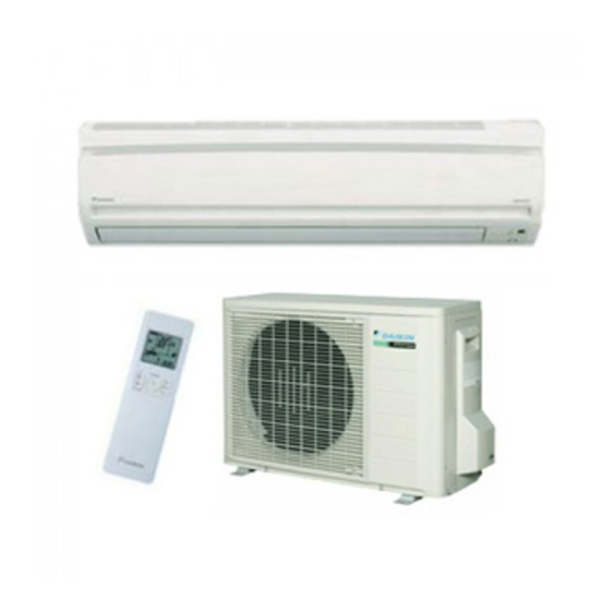
Daikin R410A Split Series Installation Manual
Hide thumbs
Also See for R410A Split Series:
- Service manual (381 pages) ,
- Installation manual (177 pages) ,
- Technical manual (44 pages)
Advertisement
Table of Contents
- 1 Installation Manual
- 2 Safety Precautions
- 3 Precautions for Selecting the Location
- 4 Outdoor Unit
- 5 Outdoor Unit Installation Drawings
- 6 Precautions on Installation
- 7 Installation Guidelines
- 8 Outdoor Unit Installation
- 9 Installing Outdoor Unit
- 10 Pump down Operation
- 11 Wiring Diagram
- 12 Trial Operation and Testing
- Download this manual
Advertisement
Table of Contents

Summary of Contents for Daikin R410A Split Series
-
Page 1: Installation Manual
INSTALLATION MANUAL R410A Split Series Models ERWQ02AAV3... - Page 2 3P403988-4B...
-
Page 3: Safety Precautions
Safety Precautions • The precautions described herein are classified as WARNING and CAUTION. They both contain important information regarding safety. Be sure to observe all precautions without fail. • Meaning of WARNING and CAUTION notices WARNING Failure to follow these instructions properly may result in personal injury or loss of life. - Page 4 • When wiring the power supply and connecting the wiring between the domestic hot water tank and the outdoor unit, position the wires so that the control box lid can be securely fastened. Improper positioning of the control box lid may result in electric shocks, fire or over heating terminals.
-
Page 5: Precautions For Selecting The Location
Accessories Accessories supplied with the outdoor unit: (A) Installation manual (B) Drain socket (C) Refrigerant charge label It is on the bottom of the packing case. (D) Multilingual fluorinated greenhouse gases label Precautions for Selecting the Location CAUTION When operating the domestic hot water heat pump in ●... -
Page 6: Outdoor Unit Installation Drawings
Outdoor Unit Installation Drawings WARNING Make sure to observe the dimensions for the space required for correct installation of the unit. Max. allowable piping length Min. allowable piping 1.5m length Wrap the insulation pipe with Max. allowable piping the finishing tape from bottom height to top. -
Page 7: Precautions On Installation
Installation Guidelines WARNING Make sure to observe the dimensions for the space required for correct installation of the unit. • Where a wall or other obstacle is in the path of outdoor unit’s inlet or outlet airflow, follow the installation guidelines below. •... -
Page 8: Outdoor Unit Installation
Outdoor Unit Installation Installing outdoor unit 1) When installing the outdoor unit, refer to “Precautions for Selecting the Location” and the “Outdoor Unit Installation Drawings.” 2) If drain work is necessary, follow the procedures below. Drain work Drain port 1) Use drain plug for drainage. 2) If the drain port is covered by a mounting base or floor surface, place additional Bottom frame foot bases of at least 30mm in height under the outdoor unit’s feet. - Page 9 • Align the centres of both flares and tighten the flare nuts 3 or 4 turns by hand. Then tighten them fully with the torque wrenches. [Tighten] [Apply oil] Apply refrigeration oil to Torque wrench Do not apply refrigeration the inner surface of the oil to the outer surface.
- Page 10 6) Turn the liquid stop valve’s rod 90 degrees counterclockwise with a hexagonal wrench to open valve. Close it after 5 seconds, and check for gas leakage. Using soapy water, check for gas leakage from the domestic hot water tank flare and outdoor unit’s flare and valve rods. After the check is complete, wipe all soapy water off.
-
Page 11: Pump Down Operation
Refrigerant piping work 7-1 Cautions on pipe handling Wall Be sure to 1) Protect the open end of the pipe against dust and moisture. place a cap. 2) All pipe bends should be as gentle as possible. Use a pipe bender Rain If no flare cap is for bending. - Page 12 Wiring WARNING • Do not use tapped wires, extension cords, or starburst connections, as they may cause overheating, electrical shock, or fire. • Do not use locally purchased electrical parts inside the product. (Do not branch the power for the drain pump, etc., from the terminal block.) Doing so may cause electric shock or fire. •...
- Page 13 Power supply terminal block Shape wires so that the service lid and stop valve cover fit securely. Use the specified wire type Firmly secure wire retainer so wire and connect it securely. terminations will not receive external stress. Observe the notes mentioned below when wiring to the power supply terminal block. Precautions to be taken for power supply wiring.
-
Page 14: Wiring Diagram
Wiring diagram Terminal strip Field wiring Connector Relay connector Connection Terminal Black Orange Blue Brown White Green Yellow Notes Refer to the nameplate of the unit for power requirements. TO INDOOR UNIT To domestic hot water tank POWER SUPPLY Power supply IN CASE OF COOLING ONLY TYPE In case of cooling only type OUTDOOR... -
Page 15: Trial Operation And Testing
Trial Operation and Testing Trial operation and testing 1-1 Measure the supply voltage and make sure that it falls in the specified range. 1-2 Carry out the test operation in accordance with the operation manual to ensure that all functions and parts, such as louver movement, are working properly. - Page 16 4P410035-1A 2016.02...


