Table of Contents
Advertisement
Quick Links
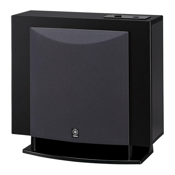
YST-FSW100
CONTENTS
TO SERVICE PERSONNEL .......................................... 2
SPECIFICATIONS / 参考仕様 ........................................ 3
INTERNAL VIEW ........................................................... 4
FRONT PANEL .............................................................. 4
REAR PANELS .......................................................... 5~6
1 0 0 9 5 7
SUBWOOFER SYSTEM
SERVICE MANUAL
IMPORTANT NOTICE
This manual has been provided for the use of authorized YAMAHA
Retailers and their service personnel.
It has been assumed that basic service procedures inherent to the industry,
and more specifically YAMAHA Products, are already known and
understood by the users, and have therefore not been restated.
WARNING:
Failure to follow appropriate service and safety
procedures when servicing this product may result in
personal injury, destruction of expensive components,
and failure of the product to perform as specified. For
these reasons, we advise all YAMAHA product owners
that any service required should be performed by an
authorized YAMAHA Retailer or the appointed service
representative.
IMPORTANT:
The presentation or sale of this manual to any individual
or firm does not constitute authorization, certification or
recognition of any applicable technical capabilities, or
establish a principle-agent relationship of any form.
The data provided is believed to be accurate and applicable to the unit(s)
indicated on the cover. The research, engineering, and service departments
of YAMAHA are continually striving to improve YAMAHA products.
Modifications are, therefore, inevitable and specifications are subject to
change without notice or obligation to retrofit. Should any discrepancy
appear to exist, please contact the distributor's Service Division.
WARNING:
Static discharges can destroy expensive components.
Discharge any static electricity your body may have
accumulated by grounding yourself to the ground buss in
the unit (heavy gauge black wires connect to this buss).
IMPORTANT:
Turn the unit OFF during disassembly and part
replacement. Recheck all work before you apply power
to the unit.
DISASSEMBLY PROCEDURES / 分解手順 ............. 7~9
BLOCK DIAGRAM ....................................................... 10
PRINTED CIRCUIT BOARD ........................................ 11
SCHEMATIC DIAGRAM .............................................. 12
PARTS LIST ........................................................... 13~18
2005
All rights reserved.
P.O.Box 1, Hamamatsu, Japan
'05.06
Advertisement
Table of Contents

Related Manuals for Yamaha YST-FSW100


Summary of Contents for Yamaha YST-FSW100
-
Page 1: Table Of Contents
YST-FSW100 SERVICE MANUAL IMPORTANT NOTICE This manual has been provided for the use of authorized YAMAHA Retailers and their service personnel. It has been assumed that basic service procedures inherent to the industry, and more specifically YAMAHA Products, are already known and understood by the users, and have therefore not been restated. -
Page 2: To Service Personnel
YST-FSW100 AC LEAKAGE TO SERVICE PERSONNEL WALL EQUIPMENT TESTER OR OUTLET UNDER TEST EQUIVALENT 1. Critical Components Information Components having special characteristics are marked s and must be replaced with parts having specifications equal to those originally installed. 2. Leakage Current Measurement (For 120V Models Only) -
Page 3: Specifications / 参考仕様
YST-FSW100 SPECIFICATIONS / 参考仕様 Weight / 質量 Type / 型式 ..Advanced Yamaha Active Servo Technology .............. 9.0 kg (19 lbs. 13 oz.) Output Power / 出力 (100 Hz, 5 ohms, 10% T.H.D.) ..................75 W Finish Silver Color ...... U, C, R, T, K, A, B, G, L, J models Input Sensitivity / 入力感度... -
Page 4: Internal View
YST-FSW100 INTERNAL VIEW 1 MAIN (3) P.C.B. 6 MAIN (9) P.C.B. (R, L models) 2 DRIVER 7 MAIN (2) P.C.B. 3 MAIN (1) P.C.B. 8 MAIN (7) P.C.B. (U, C, T, K, A, B, G, J models) 4 MAIN (4) P.C.B. -
Page 5: Rear Panels
YST-FSW100 REAR PANELS U, C models R model T model K model... - Page 6 YST-FSW100 A model B, G models L model J model...
-
Page 7: Disassembly Procedures / 分解手順
YST-FSW100 DISASSEMBLY PROCEDURES / 分解手順 (Remove parts in the order as numbered.) (番号順に部品を取り外してください。) Disconnect the power cable from the AC outlet. AC電源コンセントから、電源コードを抜いてください。 1. Removal of Base 1. ベースの外し方 a. Remove 4 screws (1). (Fig. 1) a. ①のネジ4本を外します。 (Fig. 1) b. Remove the Base. (Fig. 1) b. - Page 8 YST-FSW100 Driver スピーカーユニット Connector コネクター Fig. 2 4. リアパネルASSYの外し方 4. Removal of Rear Panel Ass’y a. Remove 14 screws (3). (Fig. 3) a. ③のネジ14本を外します。 (Fig. 3) * Screws (3) are identified with arrow marks ( * 取り外す③のネジには矢印 ( ) が印刷されています。...
- Page 9 YST-FSW100 b. Remove the Top Panel Sub Ass’y by lifting it up. b. 徐々に上面ヘマイナスドライバー等で押し上げて、トップパネ * When reinstalling it, remove old double sided adhesive ルサブASSYを取り外します。 tape from the Top Panel Sub Ass’y and attach new * 取り付け時には、トップパネルサブASSYの古い両面粘着 double sided adhesive tape to it to secure installation.
-
Page 10: Block Diagram
YST-FSW100 BLOCK DIAGRAM VOLUME POWER INPUT IC4A IC5A IC5B DRIVER L.P.F. H.P.F. L.P.F. 6dB/oct 12dB/oct 12dB/oct A.N.I.C U, C, J models LIMITER Q5,6 SYSTEM CONTROL D4,5,22,23 REGULATOR PROTECTION Q3, 4 Q17~20 D7,25 Q9,D2 POWER POWR SUPPLY REGULATOR Q10,D3... -
Page 11: Printed Circuit Board
YST-FSW100 MAIN (1) P. C. B. (W5A2) (W5A3) (W5A1) PRINTED CIRCUIT BOARD (Foil side) Lead Free Solder Used DRIVER Circuit No. U, C, J R, L K, B, G T, A MAIN (3) P. C. B. D28, D29 J48, 49... -
Page 12: Schematic Diagram
YST-FSW100 SCHEMATIC DIAGRAM IC1: STK404-120 POWER AMP. AF Power Amp MAIN (4) MAIN (1) R149 INPUT 3.9k -1.1 41.3 TR1 TR2 SYSTEM CONNECTOR 41.3 41.3 -10.8 D1 R3 LIMITER U, C, J models L.P.F. MAIN (3) 8.2k DRIVER 14.4 -14.6 24.2... -
Page 13: Parts List
YST-FSW100 PARTS LIST ELECTRICAL PARTS WARNING Components having special characteristics are marked s and must be replaced with parts having specifications equal to those originally installed. Carbon resistors (1/6W or 1/4W) are not included in the ELECTRICAL PARTS List. For the parts No. of the carbon resistors, refer to last page. - Page 14 YST-FSW100 P.C.B. MAIN Ref No. Part No. Description Remarks Markets 部 品 名 Rank WF356200 P.C.B. MAIN PCB メイン WF356300 P.C.B. MAIN PCB メイン WF356500 P.C.B. MAIN PCB メイン WF356400 P.C.B. MAIN PCB メイン VB390000 CN.BS.PIN ベースピン VB390300 CN.BS.PIN ベースピン CB4-5 WC050700 CLIP.FUSE EYF52BCY ヒューズクリップ CB6-7 WC050700 CLIP.FUSE EYF52BCY ヒューズクリップ...
- Page 15 YST-FSW100 P.C.B. MAIN Ref No. Part No. Description Remarks Markets 部 品 名 Rank VD631600 DIODE 1SS133,176 ダイオード s D28-29 VG440300 DIODE.ZENR MTZJ12C ツェナーダイオード s F1 VS822400 FUSE 1.6A 125V JUCRL ヒューズ s F1 KB002600 FUSE T630mA 250V TKABG ヒューズ s F2...
-
Page 16: Exploded View
YST-FSW100 EXPLODED VIEW 4-11 R, L models 4-34 4-32 4-23 4-26 4-31 4-32 4-37 4-32 4-19 4-1 (10) 4-36 4-11 4-32 4-25 4-34 4-37 4-23 4-1 (1) 4-19 U, C, T, K, A, 3-11 B, G, J models 4-1 (11) - Page 17 YST-FSW100 MECHANICAL PARTS Ref No. Part No. Description Remarks Markets 部 品 名 Rank Ref No. Part No. Description Remarks Markets 部 品 名 Rank WG003100 CABINET ASS'Y キャビネットASSY WF713700 TOP PANEL SUB ASS'Y CH,SI トップパネルサブASSY WG003000 CABINET ASS'Y キャビネットASSY WF404300 TOP PANEL SUB ASS'Y...
- Page 18 YST-FSW100 Parts List for Carbon Resistors Value 1/4W Type Part No. 1/6W Type Part No. Value 1/4W Type Part No. 1/6W Type Part No. YST-FSW100 1.0 Ω 3100 3100 10 kΩ 7100 7100 HJ35 HF85 HF45 HF45 1.8 Ω 3180 11 kΩ...