
Related Manuals for ADTRAN NetVanta 150 Series


Summary of Contents for ADTRAN NetVanta 150 Series
- Page 1 NetVanta 150 Series Hardware Installation Guide 1700412E1 NetVanta 150 61700412E1-34A July 2006...
- Page 2 To the Holder of the Manual The contents of this manual are current as of the date of publication. ADTRAN reserves the right to change the contents without prior notice. In no event will ADTRAN be liable for any special, incidental, or consequential damages or for commercial losses even if ADTRAN has been advised thereof as a result of issue of this publication.
- Page 3 NetVanta 150 Wireless Access Point ABG Hardware Installation Guide Conventions Conventions Notes provide additional useful information. Cautions signify information that could prevent service interruption or damage to equipment. Warnings provide information that could prevent injury or endangerment to human life. 61700412E1-34A Copyright © 2006 ADTRAN, Inc.
-
Page 4: Safety Instructions
They may explode. Check with local codes for special disposal instructions. 5. The socket-outlet shall be installed near the equipment and shall be easily accessible. Save These Important Safety Instructions Copyright © 2006 ADTRAN, Inc. 61700412E1-34A... - Page 5 Advance notification and the opportunity to maintain uninterrupted service are given. 4. If experiencing difficulty with this equipment, please contact ADTRAN for repair and warranty information. The telephone company may require this equipment to be disconnected from the network until the problem is corrected or it is certain the equipment is not malfunctioning.
- Page 6 Increase the separation between the equipment and receiver. • Connect the equipment into an outlet on a circuit different from that to which the receiver is connected. • Consult the dealer or an experienced radio/TV technician for help. Copyright © 2006 ADTRAN, Inc. 61700412E1-34A...
- Page 7 According to FCC 15.407(e), the device is intended to operate in the frequency band of 5.15GHz to 5.35GHz & 5.47GHz to 5.725HHz under all conditions of normal operation. Normal operation of this device is restricted to indoor used only to reduce any potential for harmful interference to co-channel MSS operations. 61700412E1-34A Copyright © 2006 ADTRAN, Inc.
- Page 8 Department of Communications. Cet appareil numérique respecte les limites de bruits radioelectriques applicables aux appareils numériques de Class A prescrites dans la norme sur le materiel brouilleur: “Appareils Numériques,” NMB-003 edictee par le ministre des Communications. Copyright © 2006 ADTRAN, Inc. 61700412E1-34A...
-
Page 9: Product Registration
Warranty Warranty ADTRAN will repair and return this product within the warranty period if it does not meet its published specifications or fails while in service. Warranty information can be found in the Support section of the ADTRAN website at http://www.adtran.com. - Page 10 ADTRAN website provides a variety of support services such as a searchable knowledge base, updated firmware releases, latest product documentation, service request ticket generation and trouble-shooting tools. All of this, and more, is available in the Support section of the ADTRAN website at http://www.adtran.com.
-
Page 11: Table Of Contents
Contents of ADTRAN Shipments ........ - Page 12 Table of Contents NetVanta 150 Wireless Access Point ABG Hardware Copyright © 2006 ADTRAN, Inc. 61700412E1-34A...
- Page 13 Wall Mounting the NetVanta 150 Unit ......... . 23 61700412E1-34A Copyright © 2006 ADTRAN, Inc.
- Page 14 List of Figures NetVanta 150 Wireless Access Point ABG Hardware Installation Guide Copyright © 2006 ADTRAN, Inc. 61700412E1-34A...
- Page 15 10/100BaseT Ethernet Port Pinouts ......... . 25 61700412E1-34A Copyright © 2006 ADTRAN, Inc.
- Page 16 List of Tables NetVanta 150 Wireless Access Point ABG Hardware Installation Guide Copyright © 2006 ADTRAN, Inc. 61700412E1-34A...
-
Page 17: Introduction To The Netvanta Solution
The NetVanta 150 can operate as a wireless bridge for Local Area Networks (LAN) and as a repeater to extend the range of the wireless network. This unit offers the following features: • Power from a POE enabled RJ45 Ethernet connection or from an ADTRAN external 12 V DC converter supply. •... -
Page 18: Features And Specifications
For more information on router configuration for a specific application, refer to the quick configuration documents provided on the ADTRAN website at www.adtran.com. For details on the command line interface, refer to the Command Reference Guide, also on the website. -
Page 19: Unpack And Inspect The System
After unpacking the unit, inspect it for possible shipping damage. If the equipment has been damaged in transit, immediately file a claim with the carrier and contact ADTRAN Customer Service (see Repair and Return on page 9). -
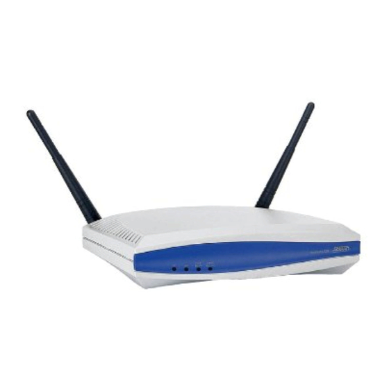
Page 20: Physical Description
Data includes network traffic as well as user data. 2.4GHz/802.11b/g There is no 802.11g or 802.11b Wireless acitvity is detected. Data is being transmitted or received via the 802.11b/g Green (flashing) Wiresless band. Data includes network traffic as well as user data. Copyright © 2006 ADTRAN, Inc. 61700412E1-34A... -
Page 21: Reviewing The Rear Panel Design
Table A-1 on page 25 for the Ethernet port pinouts. The Ethernet port provides the following: • 10BaseT or 100BaseT with a single connector • Auto-negotiation • CSMA/CD • IEEE 802.3 compatibility • Auto MDI/MDIX 61700412E1-34A Copyright © 2006 ADTRAN, Inc. -
Page 22: Unit Installation
Once both antennas are secured, the antennas may be flexed at the joint to increase reception. Mounting Options The NetVanta 150 unit can be installed in a wallmount or tabletop configuration. The following section provides step-by-step instructions for wall mounting. Copyright © 2006 ADTRAN, Inc. 61700412E1-34A... -
Page 23: Wall Mounting
Slide the keyed insets on the bottom of the unit’s chassis securely onto the screws. Proceed to the steps given in Getting Started on page 24. Figure 3. Wall Mounting the NetVanta 150 Unit 61700412E1-34A Copyright © 2006 ADTRAN, Inc. -
Page 24: Getting Started
The NetVanta 150 unit can be powered either by the LAN Ethernet connection or through the 12 VDC external supply. The Wall Supply is not included in shipment of this unit but can be requested from Adtran or your reseller. See Product Support Information on page 9 for more information on contacting Adtran. -
Page 25: Appendix A. Connector Pin Definitions
The following table provides the pin assignments for the NetVanta 150. Table A-1. 10/100BaseT Ethernet Port Pinouts Name Description Transmit Positive Transmit Negative Receive Positive 4, 5 — Unused Receive Negative 7, 8 — Unused 61700412E1-34A Copyright © 2006 ADTRAN, Inc. - Page 26 NetVanta 150 Wireless Access Point ABG Hardware Installation Guide Copyright © 2006 ADTRAN, Inc. 61700412E1-34A...
-
Page 27: Index
25 shipping contents 19 specifications 18 factory default switch 24 features 18 front panel 20 unpacking and inspecting the system 19 getting started 24 wall mounting 23 warranty 9 web GUI passwords page 24 61700412E1-34A Copyright © 2006 ADTRAN, Inc. - Page 28 NetVanta 150 Wireless Access Point ABG Hardware Installation Guide Copyright © 2006 ADTRAN, Inc. 61700412E1-34A...