Table of Contents
Advertisement
Quick Links
Advertisement
Table of Contents
Troubleshooting

Related Manuals for Panasonic KX-F680BX


Summary of Contents for Panasonic KX-F680BX
-
Page 2: Safety Precautions
KX-F680BX/KX-F2681BX SAFETY PRECAUTIONS 1. Before servicing, unplug the power cord to prevent an electric shock. 2. When replacing parts, use only the manufacturer’s recommended components. 3. Check the condition of the power cord. Replace if wear or damage is evident. -
Page 3: Battery Caution
KX-F680BX/KX-F2681BX BATTERY CAUTION CAUTION Danger of explosion if battery is incorrectly replaced. Replace only with the same or equivalent type recommended by the manufacture. Discard used batteries according to following caution: Disposal of lithium batteries should be performed by permitted, professional disposal firms knowledgeable in state govern- ment federal and local hazardous materials and hazardous waste transportation and disposal requirements. -
Page 4: Personal Safety Precautions
KX-F680BX/KX-F2681BX PERSONAL SAFETY PRECAUTIONS Be careful not to let your hair, clothes fingers, accessories, etc., become caught in any moving sections of the unit. These are driven by the carriage monitor, and the slow down gear, the paper feed roller, the pressure roller, the eject roller, the spur, the pick-up roller, etc., which are driven by the paper feed motor. -
Page 5: Specifications
KX-F680BX/KX-F2681BX SPECIFICATIONS 1. Applicable Lines: Public Switched Telephone Network 2. Document Size: Max. 216 mm (8 ") in width Max. 600 mm (23 ") in length 3. Effective Scanning Width: 208 mm(8 ") 4. Printing Paper Size: 216 mm ~ max. 50 m (8 "... -
Page 6: Location Of Controls
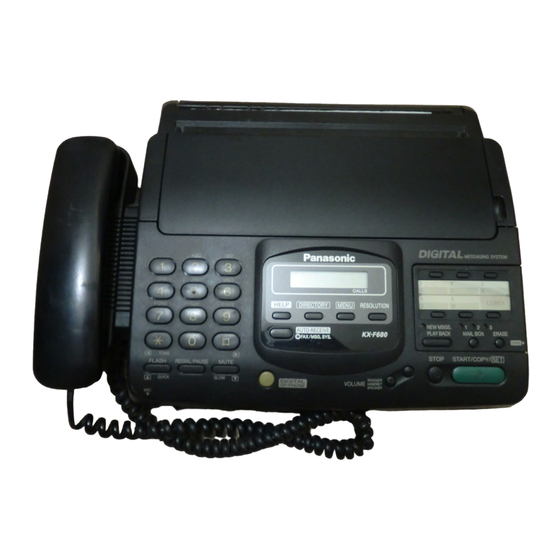
KX-F680BX/KX-F2681BX LOCATION OF CONTROLS Front View Document entrance Speaker Document feeder tray Document guide(s) Microphone Document exit Front lid open button Control panel RESOLUTION HELP Display panel Direct call stations Dial keypad DIRECTORY MENU LOWER CALLS LOWER HELP DIRECTORY PQRS... - Page 7 KX-F680BX/KX-F2681BX _Answering control buttons SELECT CHECK SELECT CHECK GREETING REPEAT SKIP MEMO/ 2WAY REC NEW MSGS PLAY BACK MAIL BOX ERASE SKIP REPEAT MEMO/2WAY REC FEATURES General Digital answering system Desktop type Voice mailbox LCD (Liquid Crystal Display) readout Tone remote control system...
- Page 8 KX-F680BX/KX-F2681BX CONNECTION Dialing mode switch: DIALING MODE Power cord Set to TONE. If you cannot dial, set to PULSE. TONE PULSE Telephone line cord Single telephone line Power outlet (220-240 V) Note: When you operate this product, the power outlet should be near the product and easily accessible.
-
Page 9: Installation
KX-F680BX/KX-F2681BX INSTALLATION 1. Installing the handset cradle If you want to use this unit with a handset, install the handset and handset cradle. To save space or to use the unit mainly for faxes, you may remove the handset cradle. -
Page 10: Installing The Recording Paper
KX-F680BX/KX-F2681BX 2. Installing the recording paper Open the back lid by lifting up the tabs located on the both side. Install a recording paper roll in the unit. Make sure that the shiny side of the paper is facing down and there is no stack, tape, or glue residue on the paper roll. -
Page 12: Maintenance List
KX-F680BX/KX-F2681BX 2-1. MAINTENANCE LIST OPERATION CHECK ITEM REMARKS Document Path Remove any foreign matter such as scrap of paper. Rollers If a roller is dirty, clean it with a damp cloth, then let dry thoroughly. See page 16. Recording Paper If the platen is dirty, clean it with a damp cloth, then let dry thoroughly. -
Page 13: Cleaning The Inside Of The Unit
KX-F680BX/KX-F2681BX CLEANING THE INSIDE OF THE UNIT If misfeeding occurs frequently, or dirty patterns or black bands appear on a copied or transmitted document, clean the document feeder rollers, sub roller, rubber flap, white plate and glass. Disconnect the power cord and the telephone line White plate cord. -
Page 14: Troubleshooting Summary
KX-F680BX/KX-F2681BX 1. TROUBLESHOOTING SUMMARY 1-1. Troubleshooting After having confirmed the abnormal condition by asking the user, troubleshoot according to the instructions in Observe the following precautions when troubleshooting. 1-2. Precautions 1) If there is trouble with the print quality or the paper feed, first check that the installation space and the print paper meets the specifications, that the paper selection lever/paper thickness lever is set correctly, and that the paper is set correctly without any looseness. -
Page 15: User Recoverable Errors
KX-F680BX/KX-F2681BX 2. USER RECOVERABLE ERRORS If the unit detects a problem, the following messages will appear in the display. DISPLAY MESSAGE CAUSE AND REMEDY There is something wrong with the unit. CALL SERVICE The back lid is open. Close it. -
Page 16: Detail Of Troubleshooting
KX-F680BX/KX-F2681BX 3. DETAIL OF TROUBLESHOOTING 3-1. Outline Troubleshooting is to make quality and reliability recover by finding out the broken component and exchange or adjustment or cleaning. We have to find out symptoms and then arrange troubleshooting method. If it's tough to finding out just a broken component, we should so arrange that block or section are specified, for example "digital board"... - Page 17 KX-F680BX/KX-F2681BX 3-3. TABLE OF TROUBLESHOOTING ITEMS FUNCTION SYMPTOM SEE THIS PAGE Unit doesn't work at all No character or faint response in the LCD Skewed sending image Page 30 Expanded print Page 30 Image is distored Page 27 Printing Black or White lateral line on printing...
- Page 18 KX-F680BX/KX-F2681BX 3-4. EASY-CHECK-LIST FUNCTION JUDGEMENT REFERENCE FAX operation transmission OK ^ NG receiving OK ^ NG FINE mode OK ^ NG Copy operation OK ^ NG HALF TONE mode Handset transceiver / receive OK ^ NG OK ^ NG Monitor sound...
-
Page 19: Adf (Auto Document Feed) Section
KX-F680BX/KX-F2681BX 3-5. ADF (Auto document feed) SECTION (1) No document feed In document setting, confirm that beep tone or not. Check the separation Replace the sen- Check the sensor spring is distorting. sor lever. lever movement. Check the sensor Replace the defec- and digital board. - Page 20 KX-F680BX/KX-F2681BX (2) Paper JAM Checks the paper jam for markings or objects stuck on the sheet. Check feed route. Cleaning or replace of defective parts. Cleaning the each rollers. (pages 109 and 110 ) Check each sensors Confirms that the location tip of the read start movement.
- Page 21 KX-F680BX/KX-F2681BX (3) Multiple feed Confirms whether the pad is dirty or not and Check separation pad. is attached correctly. Cleaning or replace the defective parts. Check the separation spring is distorting. Cleaning the each rollers. (pages 109 and 110) Replace the separation pad, roller and pressure spring.
- Page 22 KX-F680BX/KX-F2681BX (4) Skew Checks whether the document is folded or tape or staples are attached. Also checks Document setting OK? whether a different size document is set at the same time. Reset document. Checks whether there are same foreign Check feed route.
- Page 23 KX-F680BX/KX-F2681BX (5) Image is distorted Checks if there are some foreign objects Check feed route. or missing parts. Cleaning or repair the defective parts. Check of Cleaning the each rollers. relapse. (pages 109 and 110) Confirms whether the plate strokes smoothly Check white plate.
- Page 24 KX-F680BX/KX-F2681BX (6) Black or white vertical lines appear. Please copy the test chart. To thermal head section. Is line appear? (page 88) Please the white plate and target glass thoroughly. Cleaning feed route. If the dirt cannot be removed, change the white plate.
- Page 25 KX-F680BX/KX-F2681BX (8) Skewed sending image Check the setting of Reset the recording paper. recording paper Replace the recording paper roller. (9) Expanded print Check the front lid open Lock the front lid open button locked. button. Cleaning the each rollers.
- Page 26 KX-F680BX/KX-F2681BX (10) When copying or printing an abnormal sound is heard from the unit. In the document convey Alternant's source? -ance element. (Next page) In the printing section. Remove the exit-guide toward you by hand and confirm if the carriage is moved Confirm the EXIT-GUIDE by hand.
- Page 27 KX-F680BX/KX-F2681BX Check the drive gear for damage, inserted foreign Confirm the document's objects or abnormal installations. conveyance drive section. Fix clean or change the Does it recur? abnormal part. Do not apply large amounts to other parts. Re-grease (Refer to page 169)
-
Page 28: Communication Section
KX-F680BX/KX-F2681BX 3-6. COMMUNICATION SECTION Communication connection (modem) (Print defect in FAX communication) Symptom Hint General Classification Referring to the printer TEST : If only the print communication is NG and other Print a communication printing is OK, there is a high possibility that there is a problem in the digital board's modem and analog board buss. - Page 29 KX-F680BX/KX-F2681BX (1) Defective facsimile section 1 Transmit problem USER STOPPED Message on LCD TX Problem STOP key was pressed? Need to service. No problem Operation panel section. (Refer to page 80) Paper jam? ADF section. Only some of document (Refer to page 23)
- Page 30 KX-F680BX/KX-F2681BX Message on LCD Transmit Error TX Problem Pre-Feeding of docu- ment? Using auto dial to send? Doesn't start TX (Doesn't start feeding?) Do you press START key Increase "596:Transmit immediately after dialing? level set" from -10 dBm to -5 dBm or some.
- Page 31 KX-F680BX/KX-F2681BX 2 Receive problem Confirm below before starting troubleshooting. Recording paper is installed properly? RX problem Can RX something anyway? Many errors on image? No: Looks OK Change "718:Receive speed Increase "595: RX error limit select" to 7200, 4800 or 2400 value"...
- Page 32 KX-F680BX/KX-F2681BX 3 Unit can copy, but can not transmit/receive Connect the unit to the loop simulator. Switch : TX side T-R : Connect oscilloscope Modem test start (TEST CODE NO. 554) Is the four signal at Connect the PBX and Tip-Ring output? TEL.
- Page 33 KX-F680BX/KX-F2681BX C Unit can copy, but can not transmit/receive long distance or international communication The following 2 causes can be considered for this. Cause 1: The other party is executing automatic calling, the call has been received by this unit, and this time until response with a CED or DIS signal has been too long.
- Page 34 CED signal (2100 Hz), followed by a DIS signal. As here the echo cancelers stops as described in cause B, the echo of the DIS signal returns to FAX2. On the other hand, the KX-F680BX/KX-F2681BX detects the DIS signal and transmits a DCS signal.
- Page 35 KX-F680BX/KX-F2681BX Summary: Long distance and international communication operation COUNTERMEASURE SYMPTOM 1. The ANS/FAX DELAYED RING count should be 1. (user parameter: code No. 06) 2. If possible, manual transmission should be made from Does not receive in automatic mode. the transmission side.
- Page 36 KX-F680BX/KX-F2681BX (2) Communication error functions Operation: 1. Press the MENU button 3 times. 2. Press the START/SET button and ¥ button 4 times. 3. Press the START/SET button. 4. Print out. Error code table: Counter- RESULT MODE SYMPTOM CODE measure...
- Page 37 KX-F680BX/KX-F2681BX 3 Countermeasure Transmission is finished when T1 TIMER is expired. Turn ON the FAX monitor func- tion and transmit the data to the same receiver. Is FAX signal sound (DIS) heard? Is communication OK? Confirm service parameter and Confirm the receiver's FAX machine...
- Page 38 KX-F680BX/KX-F2681BX FTT is received after transmission of 2400BPS training signal. Perform communication test us- ing the LOOP simulator. Is "Fall back" executed from 9600BPS? Modem test (1) Raise the level of transmission. (Do not (TEST CODE NO.554) raise the level above the standard of each country.
- Page 39 KX-F680BX/KX-F2681BX No response after post message is transmitted three times. Inquire the receiver if the caller's document is facsimiled correctly. Is the data facsimiled correctly? Ask the service section of the receiver's FAX machine to con- firm the machine condition.
- Page 40 KX-F680BX/KX-F2681BX No post message Turn ON the FAX monitor func- tion and have the receiver trans- mit the data. Is FAX signal sound (post message) heard after the image data is received? Ask the service section of the sender's FAX machine for ex- amination.
- Page 41 KX-F680BX/KX-F2681BX Reception is finished when T1 TIME is expired. Perform communication test us- ing the LOOP simulator and check the machine reception condition. Modem test Is the data facsimiled (TEST CODE NO.554) correctly? Turn ON the FAX monitor func- tion and have the receiver in question transmit the data again.
- Page 42 KX-F680BX/KX-F2681BX DCN is received after transmission of NSC and DTC. Confirm if a mechanical trouble occurred, e.g. transmission was interrupted or document was out of place, on the receiver side (being polled). Was it a mechanical error as mentioned above?
- Page 43 KX-F680BX/KX-F2681BX DCN is received after FTT transmission. No response at the other party after MCF or CFR is transmitted. DCN is received after CFR transmission. Confirm if a mechanical trouble occurred, e.g. the caller inter- rupted the transmission. Was it mechanical error as...
- Page 44 KX-F680BX/KX-F2681BX Polling is not possible. Confirm if a mechanical trouble occurred, e.g. transmission was interrupted or document was out of place, on the receiver side (being polled). Was it mechanical error as mentioned above? Ask the receiver to set the Poll Ask the service section of the mode again and perform polling.
- Page 45 KX-F680BX/KX-F2681BX (3) Remote programming While a user is talking on the phone, a technician can set the function parameters of customer’s unit from service center. 1. A call comes in service center. 2. A technician gets a claim from a customer.
-
Page 46: Remote Programming
KX-F680BX/KX-F2681BX Summary of remote programming mode START Customer press STOP key, and hang up the handset. Enter the REMOTE PROGRAMMING ID 9,0,0,0 REMOTE PROGRAMMING MODE “Piiii” Press 3 digits code of service Press mistaken key “Pii Pii Pii” function and then press... - Page 47 KX-F680BX/KX-F2681BX A Program mode table Default Remote setting Code Function Set Value - - - - - Set date and time mm/dd/yy hh:mm - - - - - Your logo - - - - - - - - - -...
- Page 48 KX-F680BX/KX-F2681BX Code Function Set Value Default Remote setting Motor test "START" push - - - - - LED test "START" push - - - - - LCD test "START" push - - - - - 1:ON/2:OFF Paper jam detection select...
-
Page 49: Digital Board Section
KX-F680BX/KX-F2681BX 3-7. DIGITAL BOARD SECTION How to fix the digital board that don't start up the unit. (1) OVER VIEW If you see a human being down on the street, what will you do? You may talk to him. But if he doesn't answer, you check his breath or pulse, don't you. - Page 50 KX-F680BX/KX-F2681BX (2) CHECK LCD ON THE MACHINE If the digital board had broken, machine does not react at all and black square will be on the LCD. There are 5 processes to display some letters (12:00 AM) on LCD. If processes were not complete, black square will be on the LCD.
- Page 51 KX-F680BX/KX-F2681BX (3) PROCEDURE FROM OUR EXPERIENCE TO FIX Power ON plug the AC cord Look at LCD No reaction Check power line (Refer to page 58) Black squares or any charactor come. No reaction means that Power line is broken (short-circuit).
- Page 52 KX-F680BX/KX-F2681BX Please check the status (voltage) of pin 56, pin 58 and pin 60 of IC1. These status may tell you defective point. (Please use the ROM for IC status checkedin place of the original ROM(IC2) [Ref No. EC22] Oscilloscope...
- Page 53 KX-F680BX/KX-F2681BX (1) CHECKING DETAIL Please check the soldering first, it comes from our experience. Checking soldering Big ICs and resistor arry Check soldering. Visual check soldering. (Refer to page 67) IC1 RA1, RA2 IC3 RA3, RA4 Checking soldering CPUCLK OSC wave form.
- Page 54 KX-F680BX/KX-F2681BX (3) OSCILLATOR (CLK) SYSTEM CLK: 24 MHz, MODEM CLK: 49.92 MHz 24 MHz SYSTEM CLK (pin 96 of ASIC:IC1) 50 nsec/div • This point is the MHz of the SYSTEM CLK 12MHz. 49.92 MHz MODEM CLK (pin 76 of MODEM:IC5) 50 nsec/div •...
-
Page 55: Check Wave Form
KX-F680BX/KX-F2681BX (5) CHECK WAVE FORM This check needs 4 channels digital storage oscilloscope higher than 400 MHz. START Check again power line, If still no reaction replace Any wave form on the line . oscillation (12 MHz), ASIC and check again. - Page 56 KX-F680BX/KX-F2681BX location name Let's observe the wave form to fix the defective IC. : pin 132 of ASIC (IC1) Please observe A0, D0, ROMCE, RD by using digital oscilloscope. : pin 131 of ASIC (IC1) Below graph show you the wave form that is observed when unit...
- Page 57 KX-F680BX/KX-F2681BX The graphs below show you the wave form that is observed when unit (board) doesn't work. (A3 is intentionally opened at pin 135 of ASIC in this board.) Please check that active (low level) term of ROMCE is longer than good wave form, **ROMCE is active (low level) except- ing RESET is active.** and RESET is frequently coming on every 4 msec.
- Page 58 KX-F680BX/KX-F2681BX Please observe A0, D0, ROMCE, MDMCS. Below graph show you the wave form that is observed when unit (board) is working correctly. Both graph are good wave. Trigger CH1/2 MEM1 MEM2 Time/div 5V/div 5µs H1 W1 5V/div 5V/div 10.0V 5µs...
- Page 59 KX-F680BX/KX-F2681BX The graphs below show you the wave form that is observed when MODEM doesn't work. (Oscillation is not intentionally supplied to MDM.) Please compare OK form to NG form. MDMCS (pin 52 of IC5) signal is coming many times more than good wave form.
- Page 60 KX-F680BX/KX-F2681BX Below graph show you the wave form that is observed when SRAM doesn't work. (BUS line at SRAM is intentionally opened.) Please compare OK (under) to NG (upper). SRAMCS (pin 20 of IC3) signal is coming like clock. In the case of this wave form SRAM access doesn't work. If soldering, conductance is no problem, we need to replace SRAM (IC3).
- Page 61 KX-F680BX/KX-F2681BX (6) CHECK FLASH MEMORY If the unit is working correctly but VOICE GUIDANCE (voice prompt) is not heard. You should check the Flash Memory. Check Voice prompt (Service code : 784) Check soldering point Check soldering. IC1: pin12, pin13, pin106,...
- Page 62 KX-F680BX/KX-F2681BX (7) CHECK SOLDERING We should check soldering at first. Because many problem are caused by a defective soldering. How to Visual-Check the soldering Defective soldering (shorted, un-welded, oxidized...) doesn't have a good looking outward. In order words outward (gloss, brightness, form) is important for soldering. So we should do visual inspection.
- Page 63 KX-F680BX/KX-F2681BX COLD (nu-welded) SOLDERING CHIP PARTS (section) SMT PARTS cold soldering cold soldering LEADED PARTS RESISTOR ARRY (section) cold soldering cold soldering SHORTED SOLDERING SMT PARTS shorted LEADED PARTS CHIP PARTS (section) shorted shorted | 68 |...
-
Page 64: Analog Board Section
KX-F680BX/KX-F2681BX 3-8. ANALOG BOARD SECTION Returns from the customer has 2 of the defects. For example complaint HANDSET transmitting SP-PHONE transmitting How can you repair this unit? We usually check the signal flow with the circuit schematic. (If defect is only one item, we check only one of the signal routes. -
Page 65: Check Sheet
KX-F680BX/KX-F2681BX CHECK SHEET signal (SYMPTOM) ROUTE O U T ITEMS TO CHECK SP-PHONE Tx MIC- R167-C164-IC151(51-71)------C216-CN271(7)-{CN1(7)-C7-R90-IC6 (23-6)-IC5 (82-28,29) ----C23-R19----IC10 (5,6-7)-CN1(10)}-CN271(10)-C184-R182-IC151(73-63)-C203-R210- ---C24-R20-- -IC201(2-1)-C202-R201-T101-TEL LINE SP-PHONE Rx TEL LINE-T101-R202-C205-IC201(6-7)-C210-C173-R172-R173-C174-IC151(59-67)-R217-C214- IC202(10-11)-C217-CN271(9)-{CN1(9)-R11-IC10(2-1)-C19-R13-IC5(38-83)-IC6(13-17,18)--- C10-R5--- C11-R6 IC11(5,6-7)-R8-CN1(8)}-CN271(8)-C185-R183-IC151(75-41)-C158-R161-IC151(40-38)-C245- -R245-IC241(4-5,8)-SPEAKER MIC---L151-R154-C167---IC151(52,54-63)-C203-R210-IC201(2-1)-C202-R201-T101-TEL LINE Handset Tx L152-R155-C168 Handset Rx TEL LINE -T101-R202-C205-IC201(6-7)-C210-C173-R172-R173-C174-IC151(59-45,46)---C154-L154---... -
Page 66: Items To Check
KX-F680BX/KX-F2681BX signal (SYMPTOM) ROUTE O U T ITEMS TO CHECK {IC6 (6)-IC5 (82-28,29) ----C23-R19----IC10 (5,6-7)-CN1(10)}-CN271(10)-C184-R182- Greeting for TEL LINE C24-R20 MSGS for TEL LINE IC151(73-63)-C203-R210-IC201(2-1)-C202-R201-T101-TEL LINE ICM Rec TEL LINE-T101-R202-C205-IC201(6-7)-C210-C173-R172-R173-C174-IC151(59-67)-R217- C214-IC202(10-11)-C217-CN271(9)-{CN1(9)-R11-IC10(2-1)-C19-R13-IC5(38)} MIC-R167-C164-IC151(51-67)-C179-R177-IC151(68-70)-R218-C215-IC202(4-3)-CN271(9)- Greeting /Memo Rec {CN1(9)-R11-IC10(2-1)-C19-R13-IC5(38)} Note: }: digital board... - Page 67 KX-F680BX/KX-F2681BX (1) Defective ITS (Integrated telephone system) section @ No handset and speakerphone transmission/reception Following the ITS section or NCU section, search for the route between the handset microphone and the telephone line (sending), or between the telephone line and the handset speaker (receiving), or between the microphone and the telephone line (sending) or between the telephone line and the speaker (receiving) where the signal disappears.
- Page 68 KX-F680BX/KX-F2681BX 3-9. DIGITAL SPEAKER PHONE SECTION Digital speaker phone is different from analog speaker phone. What's different? Previous type (analog speaker phone) is to switch Tx or Rx. Either Tx or Rx is able to pass a telephone line or speaker, it depends on the Tx and Rx signal (voice) level. Bigger one is able to be passed the route for that signal.
- Page 69 KX-F680BX/KX-F2681BX HOW TO USE 841 SERVICE FUNCTION for DIGITALSPEAKER PHONE Please check with service function #9000 841. Connect phone line or simulater or PBX. #9000 P-SF841 ------ Don't input a dial tone (call progress Push the "speaker phone key" tone) to telephone line at the time.
-
Page 70: Power Supply Section
KX-F680BX/KX-F2681BX 3-10. POWER SUPPLY SECTION (1) Key components for troubleshooting The following components have been known to break frequently : F101, D101, Q101, IC101, D201 This comes from our experience of experimental test. For example : power supply, lighting surge voltage test, withstanding voltage test, intentional short circuit test..etc. - Page 71 KX-F680BX/KX-F2681BX (2) Troubleshooting flow chart Our recommendation for troubleshooting is as follows. This procedure comes from our experience of troubleshooting in our lab. ƒ Before turning on the power supply, you should check F101. Is F101 open? Replace F101. D101 is short.
- Page 72 KX-F680BX/KX-F2681BX 5V check 24V output OK? Replace Q201. 5V, check (DC-DC converter check) Replace IC101. 5V output OK? 24V output OK? Replace D203. 5V, check (DC-DC converter check) D201 short? 5V output OK? Replace D201. Replace IC202. 24V output OK?
- Page 73 KX-F680BX/KX-F2681BX (3) The broken parts repairing details (D101) Check short-circuit of terminal 4. If D101 is short-circuited, F101 will be melted (open). So in this case, replace the 60th parts (D101, F101). (Q101) The worst case of Q101 is a short-circuit between the Drain and Gate because damage expands to IC101.
-
Page 74: Operation Board Section
KX-F680BX/KX-F2681BX 3-11. OPERATION BOARD SECTION (1) No key operation Repair the keys. Is the Key always pressed? Check disconnection of CN5 Check IC301 (digital board) or CN301 (operation board) (operation board). (2) No LCD indication Is the disconnection of the Repair. -
Page 75: Sensor Section
KX-F680BX/KX-F2681BX 3-12. SENSOR SECTION (1) Check the read position sensor(PI301) Check the voltage at pin 15 of IC301 Check the soldering Check the soldering at R333. at R331. Document set OV When the pin No document 4~5V 16 of IC301 is low level. - Page 76 KX-F680BX/KX-F2681BX (4) Check the recording paper sensor (SW273) Check the voltage at pin 6 of IC151 Check the soldering at R275. Check the soldering at R276. Present recording paper: 0V Out of recording paper: 4~5V Replace SW273. Replace IC151. | 82 |...
-
Page 77: Read Section
KX-F680BX/KX-F2681BX 3-13. READ SECTION Clean the surface of the glass. Is the glass surface of reading section clean? Perform the scanner test. Copy a document. LED lamp of the read section light? (Service code : 555) Check the connection between CN7 and LED lamp. - Page 78 KX-F680BX/KX-F2681BX Is the amplitude at pins 2~5 of CN6 Take out cable from CN6, and 4~5 Vp-p? check the amplitude at pins 2~5 of CN6 (4~5 Vp-p). Is the voltage at pin 1 of CN6 +5 V? Check CCD board.
- Page 79 KX-F680BX/KX-F2681BX Perform the scanner test. (Refer to page 94) Is the amplitude at pins 2~5 of CN801 (CCD board ) 4~5 Vp-p? Take out CN801 (CCD board), and check the amplitude at pins 2~5 of CN6 (Digital board). (4~5 Vp-p).
- Page 80 KX-F680BX/KX-F2681BX waveform of read section 1 CCD about 1.0 Vp-p about 1.0 Vp-p CH1 GND 5 Vp-p CH2 GND 2 GATE Oscilloscope setting V: CH1 0.5 V/div 5 V/div DC couple, CHOP mode H: 1 msec / div Trigger: CH2 SLOPE (+) Probe point: GND Test point “AG”...
- Page 81 KX-F680BX/KX-F2681BX 3 -1 about 0.5 V/div 0.6Vp • AC couple 3 -2 about 0.5 V/div 1.0Vp-p AC couple about 1.5V 1 V/div 1.5V DC couple CH1 probe point 3 -1 IC801 pin 1 (CCD Board) 3 -2 CN801 pin 7 (CCD Board)
-
Page 82: Thermal Head Section
KX-F680BX/KX-F2681BX 3-14. THERMAL HEAD SECTION Is the voltage at pin 8 of CN251. (Analog Board) 0~1 V? (When copying) Is the voltage at pin 119 of IC1 4~5 V? (Digital Is the voltage at pins Board) 5,6 of CN301 23~24 V? (Power unit ) -
Page 83: Programming And Lists
KX-F680BX/KX-F2681BX 4. PROGRAMMING AND LISTS The programming functions are used to program the various features and functions of the machine, and to test the machine. Programming can be done in both the on-hook and off-hook conditions. This facilitates communication between the user and the service while programming the machine. -
Page 84: User Mode (The List Below Is An Example Of The System Setup List The Unit Prints Out.)
KX-F680BX/KX-F2681BX 4-3. USER MODE (The list below is an example of the SYSTEM SETUP LIST the unit prints out.) BASIC FEATURE LIST Code Set Value ADVANCED FEATURE LIST Code Set Value Note: The above values are default | 90 |... -
Page 85: Service Function Table
KX-F680BX/KX-F2681BX 4-4. SERVICE FUNCTION TABLE Code Function Set Value Effective Range Default Remarks Selects the pause time in 100 Setting of pause time 001 ‘600 ~100 msec 05000 msec 001 ‘ 600 msec step. Selects the line break time during Setting of flash time 01 ‘99 ~10 msec... - Page 86 KX-F680BX/KX-F2681BX Code Effective Range Function Set Value Default Remarks Lets you select the correction CCD position adjustment – 00 ‘ 30 ~ 1 mm 00 ‘30 value for main scanning direc- value set tion of the dislocated scanner. 1 : 61%...
- Page 87 KX-F680BX/KX-F2681BX Code Function Set Value Effective Range Default Remarks Selects ringer off switch when 1 : ON 1, 2 Ringer off in TEL/FAX mode a call is received in the TEL/ 2 : OFF FAX mode. Selects the tone detection in...
-
Page 88: Service Data List
KX-F680BX/KX-F2681BX 4-5. SERVICE MODE SETTING VALUES (Example of a printed out list) SERVICE DATA LIST Set Value Code SPECIAL SERVICE SETTING Code Set Value Note: The above values are default 5. TEST FUNCTIONS Code Type of Mode Test mode Function Operation after code input. -
Page 89: Button Code Table
KX-F680BX/KX-F2681BX Output the DTMF by single tone. 5 5 2 DTMF SINGLE Service Mode TEST 1..On 2..Off LED TEST Service Mode All LEDs flashes on and off, or is illuminated. 5 5 7 START 5 6 1 Check the operation button. -
Page 90: Adjusting The Feeder Pressure
KX-F680BX/KX-F2681BX 1. TABLE OF TEST EQUIPMENTS AND TOOL Test Equipment and Jig Name Jig No. Oscilloscope CCD Tool PFZZ1F780M Extension Cord PQZZ2K12Z, PQZZ8K18Z Spring Height Tool PFZZ2F780M 2. ADJUSTING THE FEEDER PRESSURE If misfeeding of document, such a multiple feeding or no feeding, occurs frequently, try to adjust the feeder pressure by following steps below. -
Page 91: Ccd Adjustments
KX-F680BX/KX-F2681BX 4. CCD ADJUSTMENTS Perform the following adjustment after replacing lens and CCD board. PREPARATION: 1) Remove the CCD unit from set. (Refer to page 109. ) 2) Make oscilloscope connections as shown in next page. 3) Attach the CCD TOOL on the CCD unit. - Page 92 KX-F680BX/KX-F2681BX ADJUSTMENT: LENS AND CCD READ POSITION ADJUSTMENT 1) Loosen the lens fixing screw and CCD board fixing screw. 2) Adjust the position of the lens and CCD board so that the waveform appears as shown in the figure below.
-
Page 93: White Level Adjustment
KX-F680BX/KX-F2681BX WHITE LEVEL ADJUSTMENT 1) Remove the CCD TOOL from CCD unit. 2) Attach the white paper on the CCD unit. 3) Attach the CCD TOOL on the CCD unit. 4) Adjust VR801 on the CCD board so that the waveform becomes 1.0 } 0.2V. - Page 94 KX-F680BX/KX-F2681BX (for white level adjustment) (for lens and CCD read position adjustment) LED Array Side edge of the glass The edge of glass and chart should be put togeter, then fix with tape. Tape Tape Reverse Make sure the position of L and R.
- Page 95 KX-F680BX/KX-F2681BX Ref. No. 1 HOW TO REMOVE THE HANDSET CRADLE CAB Procedure 1) Push the front lid open button to open the operation block. 2) Pull the Libs. 3) Remove the handset cradle cabinet. 4) Remove the 2 screws (A).
-
Page 96: How To Remove The Operation Block
KX-F680BX/KX-F2681BX Ref. No. 1 HOW TO REMOVE THE OPERATION BLOCK Procedure 1) Push the front lid open button in the direction of the arrow to open the operation block. 2) Pull both sides of the arms. (See Fig. A) 3) Pull up the operation block. -
Page 97: How To Remove The Operation Board And Lcd
KX-F680BX/KX-F2681BX Ref. No. 3 HOW TO REMOVE THE OPERATION BOARD AND LCD Procedure 1) Remove the 6 screws (A) and the operation block cover. 2 ¤3 2) Remove the 2 screws (B). 3) Pull out the 1 connector and remove the 1 flexible connector. -
Page 98: How To Remove The Bottom Frame
KX-F680BX/KX-F2681BX Ref. No. 4 HOW TO REMOVE THE BOTTOM FRAME Procedure 1) Remove the 6 screws (A). 2) Remove the 2 screws (B). 3) Remove the bottom frame. BOTTOM FRAME Ref. No. 5 HOW TO REMOVE THE ANALOG, DIGITAL BOARDS, SPEAKER AND MIC Procedure 1) Remove the 3 screws (A). -
Page 99: How To Remove The Power Supply Board And Ac Inlet
KX-F680BX/KX-F2681BX Ref. No. 6 HOW TO REMOVE THE POWER SUPPLY BOARD AND AC INLET Procedure 1) Remove the 4 screws (A) and remove the power supply board. 4, 6 2) Remove the 1 screw (B). 3) Remove the 2 connectors. -
Page 100: How To Remove The Ccd Unit
KX-F680BX/KX-F2681BX Ref. No. 8 HOW TO REMOVE THE CCD UNIT Procedure 1) Remove the 2 screws (A). 4 ¤8 2) Remove the CCD unit. CCD UNIT HOW TO CLEAN: Clean the glass of CCD unit with cloth soaked in alcohol. - Page 101 KX-F680BX/KX-F2681BX Ref. No. 10 HOW TO REMOVE THE RECORDING PAPER GUIDE Procedure 1) Push the front lid open button in the direction of the arrow to open the operation block. 2) Remove the upper guide. 3) Remove the paper upper guide.
- Page 102 KX-F680BX/KX-F2681BX Ref. No. 11 HOW TO REMOVE THE RECODING PAPER COVER Procedure 1) Pull out the both arms as showing in following Fig. A. 10 ¤11 2) Remove the recoding paper cover. RECORDING PAPER COVER Fig. A | 111 |...
-
Page 103: How To Remove The Thermal Head Roller
KX-F680BX/KX-F2681BX Ref. No. 12 HOW TO REMOVE THE THERMAL HEAD ROLLER Procedure 1) Remove the thermal head block. 10 ¤12 2) Pull out the 2 connectors. 3) Remove the 2 screws (A) of thermal head to remove the guides. 4) Replace the thermal head. -
Page 104: How To Remove The Document Tray
KX-F680BX/KX-F2681BX Ref. No. 13 HOW TO REMOVE THE DOCUMENT TRAY Procedure 1) Push the installing section in the direction of the arrow to remove the document tray. DOCUMENT TRAY | 113 |... -
Page 105: How To Replace Flat Package Ic
KX-F680BX/KX-F2681BX HOW TO REPLACE FLAT PACKAGE IC PREPARATION Sparkle Solder 115A-1, 115B-1 ESOLDER Almit Solder KR-19, KR-19RMA E Soldering iron Recommended power consumption will be between 30 W to 40 W. ° Temperature of Copper Rod 662 } 50 F (350 } 10 (An expert may handle 60~80 W iron, but beginner might damage foil by overheating.) - Page 130 KX-F680BX/KX-F2681BX TOOLS EC11 EC12 EC10 EC13 | 165 |...
- Page 132 KX-F680BX/KX-F2681BX 2.Upper Section 66-1 63-1 63-3 40-1 63-2 | 167 |...
-
Page 137: Replacement Parts List
40-1. PFHS1010Z TAPE ERC: Solid ERX: Metal Film PQ4R: Carbon PFBD1002Z2 KNOB, FRONT LID OPEN (KX-F680BX Only) ERD: Carbon ERG: Metal Oxide ERS: Fusible Resistor PFBD1002Z3 KNOB, FRONT LID OPEN (KX-F2681BX Only) PQRD: Carbon ER0: Metal Film ERF: Cement Resistor... - Page 138 PQHG556Z RUBBER, MIC COVER PFJXE0105Z HANDSET (KX-F2681BX Only) PQJS02Q62Z CONNECTOR, 2 PIN PQJA10038Y POWER CORD PFHG1024Z SPACER, SPEAKER PQJA212V HANDSET CORD (KX-F680BX Only) PFAS50PTC01Z SPEAKER PQJA212M HANDSET CORD (KX-F2681BX Only) PFJS02R20Z CONNECTOR, 2 PIN PQJA59V TELEPHONE CORD PFUS1029Y SPRING, SPEAKER...
- Page 139 KX-F680BX/KX-F2681BX This replacement parts list is forKX-F680BX/KX-F2681BX. version only. Ref. No. Part No. Part Name & Description Ref. No. Part No. Value (BATTERY) (RESISTORS) BAT10 PQPCR2032H09 LITHUM BATTERY ERD25TJ150 PQ4R10XJ224 220K PQ4R10XJ224 220K PQ4R10XJ393 PQ4R10XJ103 (CONNECTORS) PQ4R10XJ103 PQ4R10XJ393 PQJP11A19Z CONNECTOR, 11 PIN...
-
Page 140: Analog Board Parts
KX-F680BX/KX-F2681BX This replacement parts list is forKX-F680BX/KX-F2681BX. version only. Ref. No. Part No. Value Ref. No. Part No. Part Name & Description & Value PQ4R10XJ105 PQCUV1H150JC PQ4R10XJ000 JUMPER, 0 PQCUV1E104MD 0.1 PQCUV1E104MD 0.1 PQ4R10XJ000 JUMPER, 0 PQCUV1E104MD 0.1 PQ4R10XJ000 JUMPER, 0 PQCUV1E104MD 0.1... - Page 141 KX-F680BX/KX-F2681BX This replacement parts list is forKX-F680BX/KX-F2681BX. version only. Ref. No. Part No. Part Name & Description Ref. No. Part No. Part Name & Description & Value (DIODES) (OTHERS) D101 PQVDS1ZB40F1 DIODE(SI) L106 EXCELDR35 COMPONENTS COMBINATION D102 1SS131 DIODE(SI) POS101...
- Page 142 KX-F680BX/KX-F2681BX This replacement parts list is forKX-F680BX/KX-F2681BX. version only. Ref. No. Part No. Value Ref. No. Part No. Value R170 ERJ3GEYJ683 R280 ERJ3GEYJ333 R171 ERJ3GEYJ104 100K R281 ERJ3GEYJ182 1.8K R172 ERJ3GEYJ103 R282 ERJ3GEYJ473 R173 ERJ3GEYJ472 4.7K R283 ERJ3GEYJ152 1.5K R175...
-
Page 143: Operation Board Parts
KX-F680BX/KX-F2681BX This replacement parts list is forKX-F680BX/KX-F2681BX. version only. Ref. No. Part No. Value Ref. No. Part No. Part Name & Description C202 ECEA1HKS4R7 OPERATION BOARD PARTS C203 PQCUV1E104MD 0.1 C204 PQCUV1H680JC PCB3 PFLP1041M OPERATION P.C.BOARD ASS'Y (RTL) C205 PQCUV1E104MD 0.1... - Page 144 KX-F680BX/KX-F2681BX This replacement parts list is forKX-F680BX/KX-F2681BX. version only. Ref. No. Part No. Part Name & Description & Value Ref. No. Part No. Part Name & Description & Value (PHOTO COPLERS) CCD BOARD PARTS PI301 CNA1006N PHOTO ELECTRIC TRANSDUCER PCB4 PFWP2F780M CCD P.C.BOARD ASS'Y (RTL)
- Page 145 KX-F680BX/KX-F2681BX This replacement parts list is forKX-F680BX/KX-F2681BX. version only. Ref. No. Part No. Part Name & Description Ref. No. Part No. Part Name & Description & Value SWITCHING POWER SUPPLY BOARD PARTS (FUSES) F101 XBA2C50TB0L FUSE PCB5 PFLP1038BXMC POWER SUPPLY P.C.BOARD...
- Page 146 KX-F680BX/KX-F2681BX This replacement parts list is forKX-F680BX/KX-F2681BX. version only. Ref. No. Part No. Value (CAPACITORS) C101 ECQU2A224MV 0.22 C102 ECQU2A104MV C103 ECKDWS222ME 0.0022 C104 ECKDWS222ME 0.0022 C105 ECKDKC472KB 0.0047 C106 EETLD2G680 C107 ECKD3A470KBP C108 ECKD3A102KGE 0.001 C109 ECA1VHG330 C121 ECUV1H221KBM...